
Heat-Flo EC-66, EC-80 and EC-119 Light Commercial
Electric Water Heaters User Manual
LIGHT COMMERCIAL ELECTRIC WATER HEATERS
![]()

![]()
Read and understand this instruction manual and the safety messages herein before installing, operating, or servicing this water heater.
Failure to follow these instructions and safety messages could result in death or serious injury.
This manual must remain with the water heater.
![]()
If the water heater becomes immersed in water up to or above the level of the bottom of the element doors, the heater should be examined by a qualified service agency before it is placed in operation. See Page 2.
![]()
Conforms to UL1453for Electric CommercialWater Heaters.Certified to CAN/ CSASTD C22.2 No. 110-94
PLACE INSTRUCTIONS ADJACENT TO WATER HEATER & NOTIFY OWNER TO KEEP FOR FUTURE REFERENCE.
Heat-Flo, Inc. | www.heat-flo.com | Uxbridge, MA 01569
80-260 REV C_MANUAL_MODEL EC
SAFE INSTALLATION, USE, AND SERVICE
The proper installation, use, and servicing of this water heater is extremely important to your safety and the safety of others.
Many safety-related messages and instructions have been provided in this manual and on your own water heater to warn you and others of a potential injury hazard. Read and obey all safety messages and instructions throughout this manual. It is very important that the meaning of each safety message is understood by you and others who install, use, or service this water heater.

This is the safety alert symbol. It is used to alert you to potential personal injury hazards. Obey all safety messages that follow this symbol to avoid possible injury or death.
![]()
DANGER indicates an imminently hazardous situation, which (if not avoided) could result in death or injury.
![]()
WARNING indicates a potentially hazardous situation, which (if not avoided) could result in death or injury.
![]()
CAUTION indicates a potentially hazardous situation, which (if not avoided) could result in minor or moderate injury.
![]()
CAUTION used without the safety alert symbol indicates a potentially hazardous situation, which (if not avoided) could result in property damage.
All safety messages will generally tell you about the type of hazard, what can happen if you do not follow the safety message, and how to avoid the risk of injury.
IMPORTANT DEFINITIONS
Qualified Installer or Service Agency:Installation and service of this water heater requires ability equivalent to that of a Qualified Agency (as defined by ANSI below) in the field involved. Installation skills such as plumbing and electrical are required in addition to electrical testing skills when performing service.
ANSI Z223.1 2006 Sec. 3.3.83:Qualified Agency: “Any individual, firm, corporation, or company that either in person or through a representative is engaged in and is responsible for (a) the installation, testing, or replacement of gas piping or (b) the connection, installation, testing, repair, or servicing of appliances and equipment; that is experienced in such work; that is familiar with all precautions required; and that has complied with all the requirements of the authority having jurisdiction.”
GENERAL SAFETY INFORMATION
PRECAUTIONS
DO NOT USE THIS WATER HEATER IF ANY PART HAS BEEN EXPOSED TO FLOODING OR WATER DAMAGE.
Immediately, call a qualified service technician to inspect the water heater and to replace any part of the control system that has been under water.
If the unit is exposed to the following, do not operate heater until all corrective steps have been made by a qualified service technician.
- External Fire
- Damage
- Firing Without Water
GROUNDING INSTRUCTIONS
This water heater must be grounded in accordance with National Electrical Code and/ or local codes. These must be followed in all cases. Failure to ground this water heater properly may also cause erratic control system operation on ELECTRONIC CONTROL models.
This water heater must be connected to a grounded metal, permanent wiring system, or an equipment grounding conductor must be run with the circuit conductors and connected to the equipment grounding terminal or lead on the water heater.
HYDROGEN GAS (FLAMMABLE)
![]()
EXPLOSION HAZARDFlammable hydrogen gases may be present.Keep all ignition sources away from faucet when turning on hot water.
Hydrogen gas can be produced in a hot water system served by this heater that has not been used for a long period of time (generally two weeks or more). Hydrogen gas is extremely flammable. To reduce the risk of injury under these conditions, it is recommended that the hot water faucet be opened for several minutes at the kitchen sink before using any electrical appliance connected to the hot water system. If hydrogen is present, there will probably be an unusual sound, such as air escaping through the pipe as the water begins to flow THERE SHOULD BE NO SMOKING OR OPEN FLAME NEAR THE FAUCET AT THE TIME IT IS OPEN.
When servicing this unit, verify the power to the unit is turned off prior to opening the control cabinet door.
![]()
EXPLOSION HAZARDOverheated water can cause water tank explosion.Properly sized temperature and pressure relief valve must be installed in opening provided.
![]()
Read and understand this instruction manual and the safety messages herein before installing, operating, or servicing this water heater.Failure to follow these instructions and safety messages could result in death or serious injury.This manual must remain with the heater.
![]()

Before removing any access panels or servicing the water heater, make sure the electrical supply to the water is turned OFF.Failure to do this could result in death, serious bodily injury, or property damage.
![]()
Water temperature over 125˚F can cause severe burns, resulting in severe injury or death.Children, the elderly, and physically or mentally disabled are at highest risk for scald injury.Feel water before bathing or showering.Temperature limiting valves are available.Read instruction manual for safe temperature setting.
![]()
IMPROPER INSTALLATION, USE, AND SERVICE MAY RESULT IN PROPERTY DAMAGE
Do not operate water heater if any part has been exposed to flooding or water damage.Inspect anode rods regularly; replace when significantly depleted.Install in location with adequate drainage.Fill tank with water before operation.Properly sized thermal expansion tanks are required on all closed water systems.Refer to this manual for installation and service instructions.
INTRODUCTION
Thank You for purchasing this water heater. Properly installed and maintained, it should give you years of trouble-free service.
Abbreviations found in this instruction manual include:
ANSI – American National Standards InstituteAHRI – Air Conditioning, Heating, and Refrigeration Institute.NEC – National Electrical CodeNFPS – National Fire Protection AssociationUL – Underwriter’s Laboratory
PREPARING FOR THE INSTALLATION
![]()
Before removing any access panels or servicing the water heater, make sure the electrical supply to the water is turned OFF.Failure to do this could result in death, serious bodily injury, or property damage.
- Read the “General Safety Information” section of this manual first, then read the rest of the manual carefully. If you don’t follow the safety rules, the water heater may not operate safely. It could cause DEATH, SERIOUS BODILY INJURY, AND/OR PROPERTY DAMAGE.This manual contains instructions for the installation, operation, and maintenance of the electric water heater. It also contains warnings throughout that must be read and understood. All warnings and all instructions are essential to the proper operation of the water heater and your safety. READ THE ENTIRE MANUAL BEFORE ATTEMPTING TO INSTALL OR OPERATE THE WATER HEATER.Be sure to turn off all power when working on or near the electrical system of the heater. Never touch electrical components with wet hands or when standing in water.When replacing fuses, always use the correct size for the circuit.The model and rating plates on page 5 interprets certain markings into useful information. Both of these references should be used to identify the heater, its components, and optional equipment.
- The installation must conform with these instructions and the local code authority having jurisdiction and the requirements of the power company. In the absence of local codes, the installation must comply with the latest editions of the National Electrical Code, NFPA 70 or the Canadian Electrical Code CSA C22.1. The National Electrical Code may be ordered from :National Fire Protection Association1 Batterymarch ParkQuincy, MA 02269The Canadian Electrical Code is available from:Canadian Standards Association8501 East Pleasant Valley Rd.Cleveland OH, 44131
- If after reading this manual you have any questions or do not understand any portion of the instructions, call the toll free number listed on the back cover of this manual for technical assistance.A sample rating plate is shown on page 5. In order to expedite your request, please have full model and serial number available for the technician.
- Carefully plan your intended placement of the water heater. Examine the location to ensure the water heater complies with the “Locating the Water Heater” section of this manual.Installation and service of this water heater requires ability equivalent to that of a licensed tradesman or qualified agency (page 2) in the field involved. Plumbing and electrical work are required.
APPROVALS
![]()
Conforms to UL1453 for Electric Commercial Water Heaters.Certified to CAN/ CSASTD C22.2 No. 110-94
MODEL AND RATING
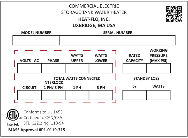
EC-66, EC-80, EC-119
FEATURES AND COMPONENTS
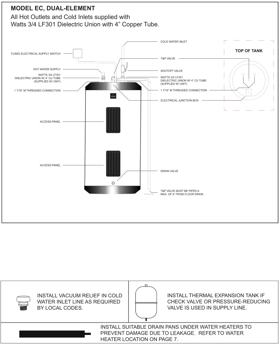
MODEL EC, DUAL-ELEMENT
All Hot Outlets and Cold Inlets supplied with Watts 3/4 LF301 Dielectric Union with 4” Copper Tube.
DIMENSIONS & CAPACITIES
Product Specifications
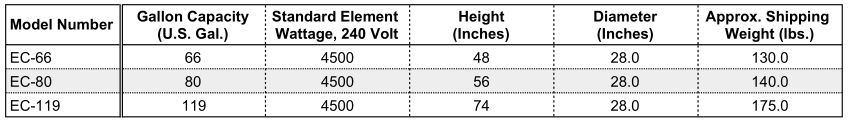
240 Volt, 1-Phase, (2) 4500 Watt Elements Wired Non-Simultaneous Standard.Inlet & Outlet Connections 3/4 Type L Copper TubeVoltage and wattage must be specified when ordering.5500 and 6100 Watts Not Available in 208 Volts.
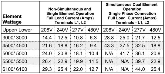
Electrical Characteristics
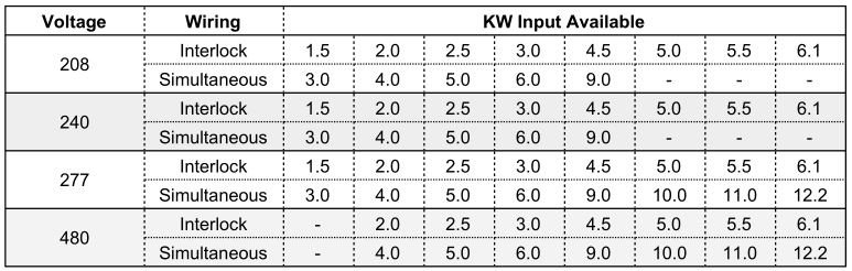
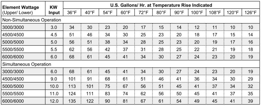
Element Availability Chart (Light-Service Commercial Electric)
Recovery Capacities
LOCATING THE WATER HEATER
FACTS TO CONSIDER ABOUT THE LOCATION
![]()
PROPERTY DAMAGE HAZARDAll water heaters eventually leak.Do not install without adequate drainage.
The water heater should be located as close as possible to/or centralized to the water piping system. The water heater should be located in an area not subject to freezing temperatures.
The water heater should be located in an area where leakage of the tank or connections will not result in damage to the area adjacent to the heater or to lower floors of the structure.
Such pans should be at least two inches deep, have a minimum length and width of at least two inches greater than the diameter of the heater and should be piped to an adequate drain.
Water heater life depends upon water quality, water pressure, and the environment in which the water heater is installed. Water heaters are sometimes installed in locations where leakage may result in property damage, even with the use of a drain pan piped to a drain; however, unanticipated damage can be reduced or prevented by a leak detector or water shut-off device used in conjunction with a piped drain pan. These devices are available from some plumbing supply wholesalers and retailers, and detect and react to leakage in various ways:
- Sensors mounted in the drain pan that trigger an alarm or turn off the incoming water to the water heater when leakage is detected.
- Sensors mounted in the drain pan that turn off the water supply to the entire home when water is detected in the drain pan.
- Water supply shut-off devices that activate based on the water pressure differential between the cold water and hot water pipes connected to the water heater.
- Devices that will turn off the gas supply to a gas water heater while at the same time shutting off its water supply.
CLEARANCES
A minimum clearance of 4” must be allowed for access to replaceable parts such as thermostats, drain valve, and relief valve.
Adequate clearance for servicing this water heater should be considered before installation, such as changing the anodes, etc…
INSTALLATION
REQUIRED ABILITYInstallation and service of this water heater requires ability equivalent to that of a qualified installer or service agency (page 2) in the field involved. Plumbing and electrical work is required.
GENERALThe installation must conform with these instructions and the local code authority having jurisdiction and the requirements of the power company. In the absence of local codes, the installation must comply with the latest editions of the National Electrical Code, NFPA 70 or the Canadian Electrical Code CSA C22.1. The National Electrical Code may be ordered from:
National Fire Protection Association1 Batterymarch Park,Quincy, MA 02269
The Canadian Electrical Code is available from:
Canadian Standards Association8501 East Pleasant Valley Rd.Cleveland OH, 44131
DO NOT test electrical system before heater is filled with water. Follow the START UP procedure in the OPERATION section of this manual.
The principle components of the heater are identified in the Features and Components illustration on page 6.
![]()
Water temperature over 125˚F can cause severe burns, resulting in severe injury or death.Children, the elderly, and physically or mentally disabled are at highest risk for scald injury.Feel water before bathing or showering.Temperature limiting valves are available.Read instruction manual for safe temperature setting.
MIXING VALVE USAGE:Water heaters are intended to produce hot water. Water heated to a temperature which will satisfy space heating, clothes-washing, dish-washing, cleaning, and other sanitizing needs can scald and permanently injure you upon contact. Some people are more likely to be permanently injured by hot water than others. These include the elderly, children, the infirm, or physically/ developmentally disabled. If anyone using hot water in you home fits into one of these groups, or if there is a local code or state law requiring a maximum water temperature at the hot water tap, then you must take special precautions. In addition to using the lowest possible temperature setting that satisfies your hot water needs, a means such as a MIXING VALVE should be used at the hot water taps used by these people or at the water heater.
MIXING VALVES for reducing point of use temperature are available and are to be set at a maximum of 125˚F. Consult a qualified installer or service agency. Follow all manufacturer’s instructions for installation of these valves. Before changing the factory setting on the thermostat, read the Temperature Regulation section in this manual.
![]()
TOXIC CHEMICAL HAZARDDo not connect to non-potable water system.
CONTAMINATED WATERThis water heater shall not be connected to any heating system(s) used with a non-potable water heating appliance.Toxic Chemicals, such as those used for boiler treatment, shall not be introduced into this system.
CIRCULATING PUMPField installed circulating pumps should be of all bronze construction.
INSULATION BLANKETSInsulation blankets are available to the general public for external use on electric water heaters but are not necessary with this product. The purpose of an insulation blanket is to reduce the standby heat-loss encountered with storage tank heaters. Your water heater meets or exceeds the EPACT and ASHRAE/ IES 90.1 standards with respect to insulation and standby loss requirements, making an insulation blanket unnecessary.
Should you choose to apply an insulation blanket to this heater, you should follow these instructions below. Failure to follow these instructions can result in fire, serious personal injury, or death.
Do not cover the Temperature and Pressure (T&P) Valve with an insulation blanket.
Do not over the instruction manual. Keep it on the side of the water heater or nearby for future reference.
Obtain new warning and instruction labels for placement on the blanket directly over the existing labels.
![]()
EXPLOSION HAZARDTemperature and Pressure Relief Valve must comply with ANSI Z21.22 and ASME code.Properly-sized Temperature and Pressure Relief Valve must be installed in opening provided.Failure to install relief valve can result in overheating and excessive tank pressure.Failure to follow these instructions can cause serious injury or death.
TEMPERATURE AND PRESSURE RELIEF VALVE
This water heater is provided with a properly rated/ sized and certified combination Temperature and Pressure Relief Valve. The valve is certified by a nationally recognized testing laboratory that maintains periodic inspection of production of listed equipment of materials as meeting the requirements for Relief Valves for Hot Water Supply Systems, ANSI Z21.22 · CSA 4.4, and the code requirements of ASME.
If replaced, the new valve must meet the requirements of local codes, but not less than a combination Temperature and Pressure Relief Valve rated/ sized and certified as indicated in the above paragraph. The new valve must be marked with a maximum set pressure not to exceed the marked hydrostatic working pressure of the water heater (150 psi = 1,035 kPa) and a discharge capacity not less than the water heater BTU/ hr or KW input rate as shown on the water heater’s model rating plate.
For safe operation of the water heater, the temperature and pressure relief valve must not be removed from its designated opening, nor plugged. The T&P Valve must be installed directly into the fitting of the water heater designated for the relief valve. Install the discharge piping so that any discharge will exit only within 6 inches above, or at any distance below, the structural floor. Be certain that no contact is made with any live electrical part. The use of more than four elbows can cause restriction and reduce the discharge capacity of the valve.
No valve or other obstruction is to be placed between the relief valve and the tank. Do not connect discharge piping directly to the drain unless a 6-inch air gap is provided. To prevent bodily injury, hazard to life, or property damage, the relief valve must be allowed to discharge water in adequate quantities should circumstances demand. If the discharge pipe is not connected to a drain or other suitable means, the water flow may cause property damage.
![]()
WATER DAMAGE HAZARDTemperature and Pressure Relief Valve discharge pipe must terminate to an adequate drain.
The Discharge Pipe:
Shall not be smaller in size than the outlet pipe size of the valve or have any reducing couplings or other restrictions.Shall not be plugged or blocked.Shall be of material listed for hot water distribution.Shall be installed so as to allow complete drainage of both the T&P Valve and the discharge pipe.Must terminate at a maximum of 6 inches above a floor drain or external to the building. In cold climates, it is recommended that the discharge pipe be terminated at an adequate drain inside the building.Shall not have any valve or other obstruction between the relief valve and the drain.
![]()
Water temperature over 125˚F can cause severe burns, resulting in severe injury or death.Children, the elderly, and physically or mentally disabled are at highest risk for scald injury.Feel water before bathing or showering.Temperature limiting valves are available.Read instruction manual for safe temperature setting.
The T&P Valve must be manually operated at least once a year. Caution should be taken to ensure that:
- no one is in front of or around the outlet of the T&P Valve discharge line, and
- the water manually discharged can cause bodily injury or property damage because the water may be extremely hot.
If after manually operating the T&P Valve it fails to completely reset and continues to release water, immediately close the cold water inlet to the water heater, follow the instructions in this manual, and replace the T&P Valve with a properly rated/ sized new one.
If you do not understand these instructions or have any questions regarding the T&P Valve, call the toll free number listed on the back cover of this manual for technical assistance.
CLOSED WATER SYSTEMSWater supply systems may (because of code requirements or such conditions as high line pressure, among others) have installed devices such as pressure reducing valves, check valves, and back flow preventers. Devices such as these cause the water system to be a closed system.
THERMAL EXPANSIONAs water is heated, it expands (thermal expansion). In a closed system, the volume of water will grow when it is heated. As the volume of the water grows, there will be a corresponding increase in water pressure due to thermal expansion. Thermal expansion can cause premature tank failure (leakage). This type of failure is not covered under the limited warranty. Thermal expansion can also cause intermittent T&P Valve operation: water discharged from the valve due to excessive pressure build-up. This condition is not covered under the limited warranty. The T&P Valve is not intended for the constant relief of thermal expansion.
A properly-sized thermal expansion tank should be installed on all closed systems to control the harmful effects of thermal expansion. Contact a local plumbing service agency to have a thermal expansion tank installed.
ELECTRICAL
![]()
Before removing any access panels or servicing the water heater, make sure the electrical supply to the water is turned OFF.Failure to do this could result in death, serious bodily injury, or property damage.
GENERALThe installation must conform with these instructions and the local code authority having jurisdiction, and the requirements of the power company. In the absence of local codes, the installation must comply with the current editions of the National Electrical Code, NFPA 70 or the Canadian Electrical Code, CSA C22.1.
An electrical ground is required to reduce risk of electrical shock or possible electrocution. The water heater should be connected to a separate grounded branch circuit with over-current protection and disconnect switch. The water heater should be grounded in accordance with national and local codes.
Voltage applied to the heater should not vary more than +5% to -10% of the model rating plate marking for satisfactory operation.
DO NOT ENERGIZE THE BRANCH CIRCUIT FOR ANY REASON BEFORE THE HEATER TANK IS FILLED WITH WATER. DOING SO WILL CAUSE THE HEATING ELEMENTS TO BURN OUT AND VOID WARRANTY.
The factory wiring is attached to a terminal block within the junction box. The water heater should be connected to a separate, grounded branch circuit with over-current protection and disconnect switch. The water heater should be grounded in accordance with national and local codes.
BRANCH CIRCUITThe branch circuit wire size should be established through reference to the current edition of NFPA-70, the National Electric Code or other locally approved source in conjunction with the heater amperage rating. For convenience, portions of the wire size tables from the Code are reproduced here. The branch circuit should be sized at 125% of the heater rating and further increase wire size as necessary to compensate for voltage drop in long runs.
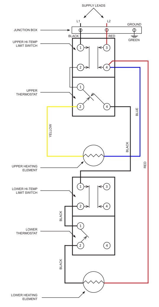
CALCULATING AMPERAGE/OVER-CURRENT PROTECTIONTwo-wire H-6 circuit for dual-element heater is equipped with high-limit control and single phase power input.The standard heater with dual elements is factory-wired for non-sumultaneous operation. In addition, a ground conductor is required.Standard-unit element connections are for non-simultaneous operation. This means only one element at a time operates.
WIRING DIAGRAMS
H-6 CIRCUIT
WIRED 208 OR 240 VOLT NON-SUMULTANEOUS SINGLE PHASE OPERATION
![]()
Before removing any access panels or servicing the water heater, make sure the electrical supply to the water is turned OFF.Failure to do this could result in death, serious bodily injury, or property damage.
This is an example of calculating heater amperage for both types of element operation. From this, the branch circuit conductor and over-current protection sizing can be established.
The example is of a three-phase 240-volt unit with two 6 KW elements. The notations are for units field-converted to single-phase. Check the heater model and rating plate for actual specifications and substitute those values in the following:
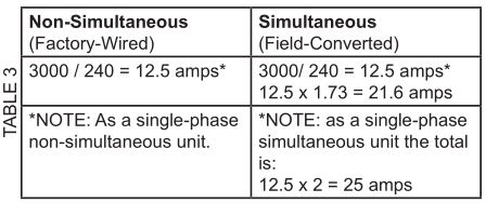
The rating of the over-current protection should be computed on the basis of 125% of the total connected load amperage. Where the standard rating and settings do not correspond with this computation, the next higher standard rating or setting should be selected.
Portion of Table 310-16 (NFPA-70) follows:Allowable Ampacities of Insulated Copper Conductors
No more than three conductors in Raceway or Cable or Direct Burial (Based on Ambient Temperature of 86˚F).
These ampacities relate only to conductors described in Table 310-13 in Code.
For ambient temperatures that over 86˚F, see Correction Factors (Note 13 in Code).
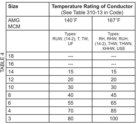
Portion of Table 310-18 follows:Allowable Ampacities of Insulated Aluminum and Copper – Clad Aluminum Conductors.Not more than three conductors in Raceway or Cable or Direct Burial (based on Ambient Temperature of 86˚F.These ampacities relate only to conductors described in Table 310-13 in Code.For ambient Temperatures over 86˚F, see correction Factors, Note 13 in Code.

OPERATION
GENERALRefer to the Features and Components section of this manual (page 6) for the location of components mentioned in the instructions that follow.
NEVER turn on power to the water heater without being certain the water heater is filled with water and a Temperature and Pressure Relief Valve is installed in the relief valve opening.
DO NOT TEST ELECTRICAL SYSTEM BEFORE HEATER IS FILLED WITH WATER. FOLLOW FILLING AND START-UP INSTRUCTIONS IN OPERATION SECTION.
![]()
Full power is present whenever the cabinet door is opened.
![]() PROPERTY DAMAGE HAZARDIn order to avoid water heater damage, fill tank with water before operating.
PROPERTY DAMAGE HAZARDIn order to avoid water heater damage, fill tank with water before operating.
FILLING THE WATER HEATER
- Turn off the electrical disconnect switch.
- Close the water heater drain valve.
- Open a nearby hot water faucet to permit the air in the system to escape.
- Fully open the cold water inlet pipe valve allowing the heater and piping to be filled.
- Close the hot water faucet as water starts to flow. The heater is now ready for START-UP and TEMPERATURE REGULATION.
INITIAL START-UP
The following checks should be made by the installer when the heater is placed into operation for the first time.
- Turn off the electrical disconnect switch.
- Open the front panel or top access cover. Check all water and electrical connections for tightness. Also check connections on top and/or sides of heater. Repair water leaks and tighten electrical connections as necessary.
- Depress the red manual reset button on each Thermostat/ECO combination control. (See Figure 5, 6, 7, or, 8).
- Turn on the electrical disconnect switch.
- Observe the operation of the electrical components during the first heating cycle. Use care as the electrical circuits are energized.
- Close the front panel or top access cover.
Temperature control and contactor operation should be checked by allowing heater to come up to temperature and shut off automatically. Use care as the electrical circuits are energized.
DRAINING THE WATER HEATERThe water heater must be drained if it is to be shut down and exposed to freezing temperatures. Maintenance and service procedures may also require draining the heater.
- Turn off the electrical disconnect switch.
- Open the hot water valve until the water is cool, then close the supply water inlet valve to the heater.
- Attach hose to outlet opening of the drain valve and direct end to drain.
- Open a nearby hot water faucet and the heater drain valve.
- If the heater is being drained for an extended shutdown, it is suggested the drain valve be left open during this period. The hose may be removed.
Follow the FILLING instructions when restoring hot water service.
![]()
BURN HAZARDHOT WATER DISCHARGEKEEP CLEAR OF DRAIN VALVE.
TEMPERATURE REGULATION
![]()
Water temperature over 125˚F can cause severe burns, resulting in severe injury or death.Children, the elderly, and physically or mentally disabled are at highest risk for scald injury.Feel water before bathing or showering.Temperature limiting valves are available.Read instruction manual for safe temperature setting.
THE WATER HEATER IS EQUIPPED WITH AN ADJUSTABLE THERMOSTAT TO CONTROL WATER TEMPERATURE. HOT WATER AT TEMPERATURES DESIRED FOR AUTOMATIC DISHWASHER AND LAUNDRY USE CAN CAUSE SCALDS, RESULTING IN SERIOUS PERSONAL INJURY AND/OR DEATH. THE TEMPERATURE AT WHICH INJURY OCCURS VARIES WITH THE PERSON’S AGE AND TIME OF EXPOSURE. THE SLOWER RESPONSE TIME OF CHILDREN, AGED, OR DISABLED PERSONS INCREASES THE HAZARD TO THEM. NEVER ALLOW SMALL CHILDREN TO USE A HOT WATER TAP OR TO DRAW THEIR OWN BATH WATER. NEVER LEAVE A CHILD OR DISABLE PERSON UNATTENDED IN A BATHTUB OR SHOWER.
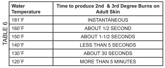
It is recommended that lower water temperatures be used to avoid the risk of scalding. It is further recommended, in all cases, that the water temperature thermostats (see Table 6) be set for the lowest temperature, which satisfies your hot water needs. This will also provide the most energy efficient operation of the water heater.
Table 6 shows the approximate time-to-burn relationship for normal adult skin. The thermostats on your water heater have a linear relationship between degrees of angular rotation and the corresponding change in temperature. Thus, rotating the temperature adjustment indicator 30 angular degrees will result in a 10˚F change in water temperature.
TEMPERATURE ADJUSTMENTThe water heater is supplied with thermostats that may come from different manufacturers and have different temperature indications as described next:
APCOM THERMOSTATSH-6 circuit thermostats have three designated set points: LO, MED, and HI (see Figure 5). The approximate equivalent temperatures for these three settings are:
LO = 140˚FMED = 160˚FHI = 181˚F
These thermostats are set from the factory at the LO setting. The over temperature device (ECO High-Limit) attached to each thermostat has a manual reset. The H-6 circuit thermostat is adjustable from approximately 130˚F to 170˚F (see Figure 6). these thermostats are set from the factory at approximately the 125˚F setting. The over-temperature device (ECO High-Limit) attached to each thermostat has a manual reset.

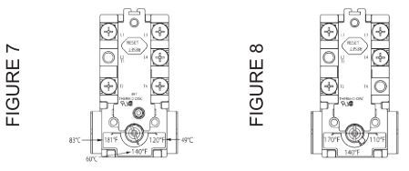
THERMODISC THERMOSTATSH-6 circuit thermostats are adjustable from approximately 120˚F (lowest setting) to 181˚F (highest setting) (see Figure 7). The H-6 circuit thermostat is adjustable from approximately 110˚F to 170˚F (see Figure 8). These thermostats are set atapproximately the 125˚F setting. The over-temperature device (ECO High-Limit) attached to each thermostat has a manual reset.
NOTE: It is not necessary to adjust the upper thermostat for a dual-element unit; however, if it is adjusted above the factory set-point of 125˚F, it is recommended that it not be set higher than the lower thermostat setting.
To change the temperature setting:
- DANGER: Turn off the heater electrical supply. Do not attempt to adjust the thermostat with power on.
- Open the junction box door (for upper thermostat of dual-element water heater only) and/or remove the (lower) thermostat access panel. Do not remove the plastic personnel protectors covering the thermostats. The thermostat is factory pre-set at 125˚F.
- Using a flat-head screwdriver, rotate the adjusting know to the desired temperature setting.
- Replace the covers and access panels, and turn on the heater electrical supply.
MAINTENANCE
![]()
GENERALPeriodically, the drain valve should be opened and the water allowed to run until it flows clean. This will help to prevent sediment buildup in the tank bottom.
Periodically, check the Temperature and Pressure Relief Valve to ensure that it is in operating condition. Lift the lever at the top of the valve several times until the valve seats properly and operates freely.
Water heater maintenance includes periodic tank flushing and cleaning, and removal of lime scale from the heating element.
TROUBLESHOOTING CHECKLIST
CHECKLISTBefore calling for service, check the following points to see if cause of trouble can be identified and corrected. Reviewing this checklist may eliminate the need of a service call and quickly restore hot water service. See page 6 in this manual to identify and locate water heater components.
![]()
Before removing any access panels or servicing the water heater, make sure the electrical supply to the water is turned OFF.Failure to do this could result in death, serious bodily injury, or property damage.
NOT ENOUGH OR NO HOT WATER
- Be certain the electrical disconnect switch serving the water heater is in the ON position.
- Check the fuses.The electrical disconnect switch usually contains fuses.
- If the water was excessively hot and is now cold, the high limit switch may have activated.Large demands require a recovery period to restore water temperature.
- The capacity of the heater may have been exceeded by a large demand for hot water.
- Cooler incoming water temperature will lengthen the time required to heat water to the desired temperature.
- Look for hot water leakage.
- Sediment or pipe scale may be affecting water heater operation.
ABNORMAL SOUNDS
- Sediment or lime scale accumulations on the elements causes sizzling and hissing noises when the heater is operating.
WATER LEAKAGE IS SUSPECTED
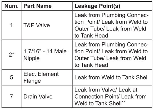
Refer to Leakage Checkpoint (next section).
- Check to see if the heater drain valve is tightly closed.
- If the outlet of the relief valve is leaking, it may be due to one or more of the following:Excessive water temperatureFaulty relief valveExcessive water pressure
- Excessive water pressure is the most common cause of relief valve leakage. It is often caused by a “closed system.” See Closed Water Systems and Thermal Expansion in the “Installation” section of this manual.
- Examine the area around the element for gasket leakage.Tighten the elements, or (if necessary) follow the WATER AND LIME SCALE REMOVAL procedure to replace the gaskets.
IF UNABLE TO IDENTIFY OR CORRECT THE SOURCE OF MALFUNCTION
- Turn the power supply to the water heater off.
- Close the supply water inlet valve to the heater.
- Contact a Qualified Service Agency in your area. Call the toll free phone number on the back cover of this Instruction Manual for assistance in locating a service agency in your area.
REPLACEMENT PARTSCall the phone number on the back cover of this Instruction Manual for assistance in locating replacement parts. When ordering parts, specify complete model no. (see rating plate), quantity, and name of the part desired. Standard hardware items should be purchased locally.
LEAKAGE CHECKPOINTS
REPLACEMENT PARTS
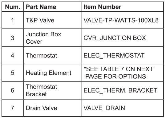

*Fits Watts 3/4 LF301 Dielectric Union (included with unit).
REPLACEMENT HEATING ELEMENTS

SPECIFICATION
The water heater(s) shall be EC-XXXXX Model(s) No. ______ as manufactured by Heat-Flo or an approved equal. Heater(s) shall be rated at ______ kW, ______ volts, single-phase, 60 cycle AC, and listed by Intertek. Models shall meet the standby loss requirements of the U.S. Department of energy and current edition of ASHRAE/ IES 90.1. Tank(s) shall be ______-gallon capacity. Heater(s) shall have 150 psi working pressure. Tanks are all Stainless Steel. Electric heating elements shall be low watt density with Incoloy sheath and 316L Stainless Steel flange. Each element shall be controlled by an individually mounted thermostat and high-temperature cutoff switch. The outer jacket shall be thermoplastic and shall enclose the tank with foam insulation. Electrical junction box on the top of the heater. The brass drain valve shall be located in the front for ease of servicing. Heater tank shall have a 3-year limited warranty as outlined in the written warranty. Fully illustrated manual to be included.
![]()
COMMERCIAL ELECTRIC WATER HEATER LIMITED WARRANTY
EFFECTIVEFor 3 Years, in the event of a tank leak, we will repair or, at our discretion, replace the defective water heater. For 1 Year, in the event of part failure, we will repair or, at our discretion, replace the defective part. We warrant this product against defects in materials or workmanship as described in this document if installed within the United States or Canada and provided the product remains at its original place of installation. Warranty coverage begins the date of installation OR the date of manufacture if installation cannot be verified.
WHAT IS COVEREDSubject to these terms, in the event of defect in materials and/or workmanship resulting in a tank leak during the first three years, we will: Replace the water heater should the tank leak. Subject to these terms, in the event of a defect in materials and/or workmanship appearing during the first year, we will: Repair or, at our discretion, replace any part of the water heater covered under this limited warranty excluding parts subject to normal maintenance (Example: anode rod, filter, etc…).
WHAT IS NOT COVERED
- Problems caused by improper: Voltage, wiring, fusing
- Failure to follow applicable codes
- Failure to follow printed instructions
- Abuse, misuse, accident, fire, flood, Acts of God
- Improper installation, sizing, delivery, or maintenance
- Claims related to rust, noise, smell, or taste of water
- Failure to conduct authorized factory start up if required
- Alterations to the water heater
- Non-outdoor heaters installed outdoors
- Damages due to a failure to allow for thermal expansion
- Heat-exchanger failure due to lack of adequate/ proper supply of water
- Heaters moved from their original location
- Service trips to explain proper installation, use, or maintenance of the product/unit or to describe compliance requirements under applicable codes and regulations
- Charges related to accessing your heater including, but not limited to: Door/wall removal, equipment rental, etc…
- Replacement parts after expiration of this warranty
LIMITATIONNOTWITHSTANDING ANYTHING ELSE TO THE CONTRARY, THIS IS YOUR SOLE AND EXCLUSIVE WARRANTY. ALL OTHER WARRANTIES, INCLUDING A WARRANTY OF MERCHANTABILITY OR FITNESS FOR PARTICULAR PURPOSE, ARE EXPRESSLY DISCLAIMED. SELLER SHALL NOT BE LIABLE FOR ANY CONSEQUENTIAL, INCIDENTAL, SPECIAL, PUNITIVE, OR OTHER INDIRECT DAMAGES. TOTAL LIABILITY ARISING AT ANY TIME SHALL NOT EXCEED THE PURCHASE PRICE PAID, WHETHER BASED ON CONTRACT, TORT, STRICT LIABILITY, OR ANY OTHER LEGAL THEORY.
SERVICES INQUIRIES:For service inquiries, call the telephone number listed below. Be prepared to provide the following information: Name, address, and telephone number; the model and serial number of the water heater; proof of installation; and a clear description of the problem.
For your records, fill in the product:
Serial: ___________________Model: ___________________
Heat-flo, Inc., 15 Megan Ct., P.O. Box 612, Uxbridge, MA 01569 USATel: 508-278-2400 | Fax: 508-278-2466 | www.heat-flo.com
![]()
HEAT-FLO, INC.P.O. BOX 612UXBRIDGE, MA 01569508-278-2400www.heat-flo.com
Heat-Flo EC-66, EC-80 and EC-119 Light Commercial Electric Water Heaters User Manual – Heat-Flo EC-66, EC-80 and EC-119 Light Commercial Electric Water Heaters User Manual –
[xyz-ips snippet=”download-snippet”]