
EATITZ-DIN 616
Installers manual
Firmware 0.1501.02.2021Ver 2021-A
INTRODUCTION
The Heat Z-DIN 616, which is built upon the wireless Z-Wave communication protocol, has 6 relay-driven outputs and 6 digital inputs. The unit is a multi-purpose Z-Wave I/O module, which can be used for many applications. For example, the Heat Z-DIN 616 provides the possibility to control other systems via the Z-Wave network, by utilizing the 6 outputs as a kind of hand-over function to another automation system.
The relay outputs (controlled through the Z-Wave network) are suitable for switching up to six 230VAC loads. In connection with simultaneous connection to SELV (Safety Extra Low Voltage) and 230VAC power circuits for relay outputs, relays must be considered as two groups, where the first group includes output 1 to 3 and the second group includes outputs 4 to 6. This ensures complete separation between the SELV and 230VAC circuits. If one of the relays in the group is connected to a SELV circuit, the remaining outputs are not allowed to be connected to 230VAC or another circuit that is not a SELV circuit. For example, the relay outputs of the Heat Z-DIN 616 module can be used to control the 230Vac power supply outlet, making it possible to turn on and disconnect the electrical outlets directly through the Z-Wave network. For safety reasons, however, it is not recommended to use the Heat Z-DIN 616 to connect electrical outlets that are normally used for hazardous tools and machinery.
The 6 digital inputs of the Heat Z-DIN 616 are useful for various purposes, where potential-free contacts or Open Collector outputs may be connected. The inputs may be configured to different trigger modes; leading edge, trailing edge or level triggered. The Heat Z-DIN 616’s inputs may be programmed to control other Z-Wave devices when the inputs are activated, by sending Z-Wave commands over the Z-Wave network to e.g. Z-Wave relay modules, dimmer units etc. Heat Z-DIN 616 allows sending different types of Z-Wave commands by utilizing the different association groups for the 6 inputs. In addition, the Heat Z-DIN 616 also acts as a repeater, thus extending the range of the Z-Wave network. By default, the Heat Z-DIN 616’s inputs and outputs are set to operate as toggle relays. Input 1 controls output 1, input 2 controls output 2, etc. This functionality can be modified via the configuration parameters 3-8 and 13-18.
BEHAVIOR WITHIN THE Z-WAVE™ NETWORKThis device may be operated within any Z-Wave network with Z-Wave-certified devices from other manufacturers. All non-battery-operated nodes within the network will act as repeaters regardless of the manufacturer to increase the reliability of the network. On delivery, the device does not belong to any Z-Wave network. The device needs to be added to an existing network to communicate with the other devices within it. Devices may also be removed from a network. The add/remove processes are initiated by the primary controller of the Z-Wave network.

INSTALLATION
Installation must be done by a qualified electrician in accordance with the National Building codes. Before installation, disconnect any power to the device mains. During the installation of the device, power to the device must be disconnected AT ALL TIMES!
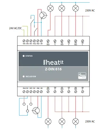
The Heat Z-DIN 616 must be connected to a 24 Volt AC or DC power supply via the terminals labeled ”Vin”. The polarity is of no importance. The supply must be dimensioned to allow the supplied module with enough power to enable all relays to be activated. Regarding power consumption: see the technical details section.
3.1 Relay outputs
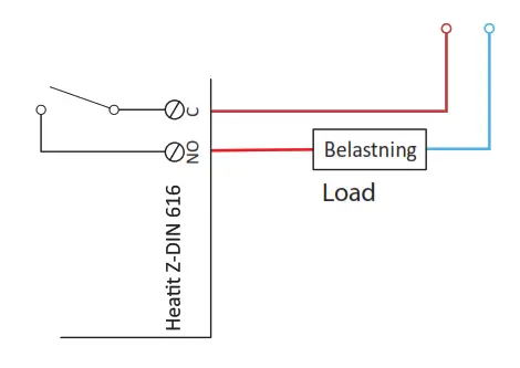
The 6 outputs of the Heatit Z-DIN 616 module consist of 1-pole SPST connectors (Single-Pole Single-Throw). As default, the outputs are configured to be controlled by their corresponding input (output 1 is controlled by input 1, etc.). This functionality is changeable via configuration parameters 13 to 18.
3.2 InputsThe digital inputs of the Heatit Z-DIN 616 module can be connected to different types of control signals – switches, relays, open-collector outputs, etc.
The inputs IN1, IN2, IN3, IN4, IN5, and IN6 which operate as active low, are pr. default pulled up to 3V DC and must be pulled low in order to work, by mounting e.g. a contact between [IN1.IN6] and 0V. The inputs can be configured to different trigger functions using configuration parameters 3, 5, 7, 9, 11, and 13. The default setup of the inputs is switching between the modes on/off, or off/on the leading edge of the input signal, i.e. on each activation of the input, the mode will change (toggle relay function). The following modes may be set up for input:Input mode 1When the configuration parameters for the inputs are set to the value ’1’, the inputs will have the functionality as shown in the figure below:
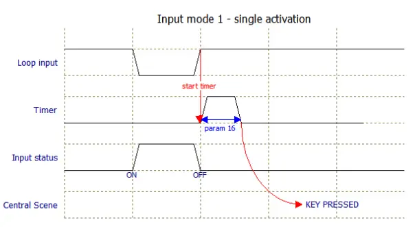
Loop input:Physical signals on the input. Will become 0V when the input is shortened by e.g. a contact.Timer:A software timer that begins when the input is deactivated. The time is set in config. parameter 16.Input status:The status of the input is reported through the various association groups.Central scene:Specifies which type of Central Scene message is sent through the Lifeline association group.
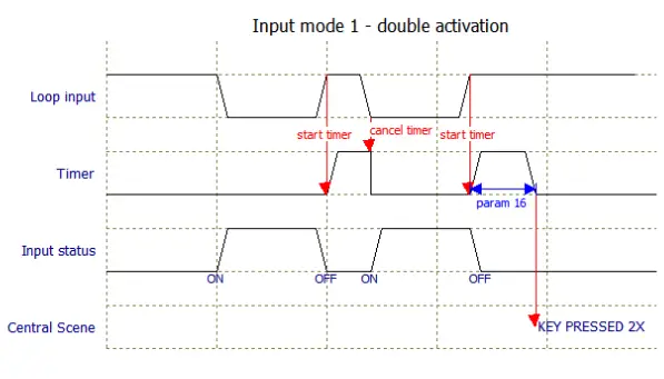 The figure above shows how a double activation is detected. The two activations must happen within the time specified in configuration parameter 16 to be accepted as a double activation.
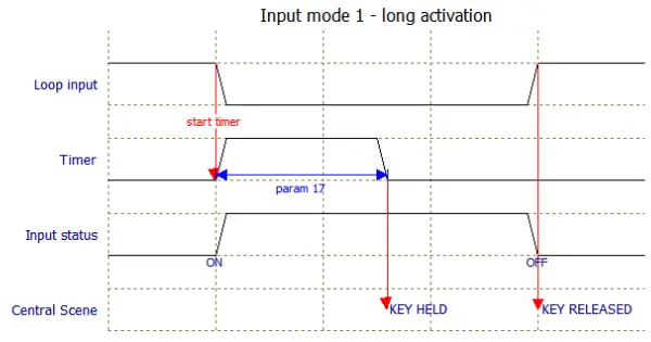
The figure above shows how the timing works at a long activation, where the activation must be longer than the time specified in configuration parameter 17 to be accepted as a long activation (Central Scene Key Held).
Input modeWhen the configuration parameters for the inputs are set to the value ’2’, the inputs will have the same functionality as Input Mode 1 except the input signal is inverted, making it possible to use contacts of the type ’normally-closed.
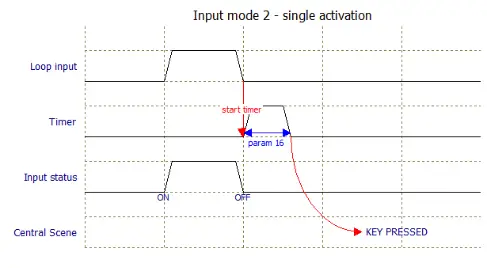
Other activations are corresponding to input mode 1 except the Loop Input is inverted.
Input mode When configuration parameters for input is set to the value ’3’ the inputs will work as a toggle switch; the first activation will give the input the status ”ON”, next activation will change the status to ”OFF”. See figure below.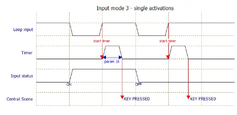
Other activation scenarios are as described in Input Mode 1, except the input status will change for each activation of the input instead of following Loop input.
Input modeWhen the configuration parameters for the inputs are set to the value ’4’, the inputs will have the same function as Input Mode 3 except the detection of the input signal is inverted, making it possible to use contacts of the type ’normally-closed.
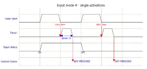
Other activations are corresponding to Input Mode 3, except the Loop Input is inverted.
Input mode 5When the configuration parameters for the inputs are set to the value ’5’, the inputs will have the same function as for Input Mode 1, except the input status can be prolonged with a configurable timer(configuration parameter 4, 6, 8, 10, 12 and 14). This makes it possible to control e.g. lighting where the input is connected to a motion detector. So when a movement is detected the status is preserved during the time preset in the associated timer.
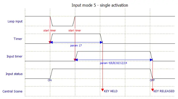
As illustrated above, a KEY HELD Central Scene notification will appear even though the activation on the input is shorter than configuration parameter 17. This is because the status on the input is prolonged with the time specified in the configuration parameter for the input timer (parameter 4/6/8/10/12/14).
Input mode 6When the configuration parameters for the inputs are set to the value ’6’ the inputs will have same function as for Input Mode 5, except the detection of the input signal is inverted, making it possible to use contacts of the type ’normally-closed.
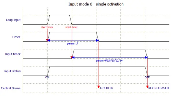
Other activations are corresponding to Input Mode 5, except the Loop Input is inverted.
4. FACTORY RESETHeat Z-DIN 616 can be reset to factory settings, i.e. all configurations and device addresses will be reset to default settings. The device must then be reconnected to the Z-Wave network.
Resetting is performed by activating the small push button marked ”INCLUSION” located on the front for at least 10 seconds until the LED flashes briefly. Slide a pin, toothpick, or similar through the small hole to activate the push button.
This procedure only applies to cases where the primary network controller is not available or not operational.
5. ADDING THE HEATIT Z-DIN 616 TO THE Z-WAVE NETWORKUpon delivery, the Heat Z-DIN 616 module has not been added to any Z-Wave network. In order to communicate with other devices in the Z-Wave network, Heatit Z-DIN 616 must be added to the network. Devices may also be removed from the Z-Wave network if they are to be used in another installation. Both processes are initiated by setting the central network controls in either add or remove mode. Please refer to the network controller’s manual on how to set the central controls in either add or remove mode. Next, activate the add/remove mode on the Heat Z-DIN 616 device by pressing the small button marked ”INCLUSION”, through the hole in the front of the module, after which the status LED will start flashing.
NB! If the device already belongs to a network, the device must be removed before it can be added to the current network, otherwise, the adding process will fail.
6. ASSOCIATIONSZ-Wave devices interact with other Z-Wave devices. The relationship between one device controlling another device is called an association. In order to control a subordinate device, the controlling device needs to maintain a list of devices that will receive controlling commands. These lists are called ”Association Groups”. They are always related to the specific event triggered (e.g., sensor reports). In case the event is triggered, all devices stored in the respective association group will receive a joint wireless command.
6.1 Association groups
| RELAY DEVICE | THE MAIN DEVICE |
| Device 1 (Endpoint 1)Group 1/1 | Relay output 1Lifeline. Lifeline group for the entire module.Sends Basic Report On / Off when relay output 1 is activated.This group is typically used for reporting the actual status of the output to the Controller to let the Controller visualize the output in its user interface. Max. nodes in group: 1 |
| Device 2 (Endpoint 2)Group 1/- | Relay output 2
Lifeline. Lifeline group for the entire module. Sends Basic Report On / Off when relay output 2 is activated. This group is typically used for reporting the actual status of the output to the Controller to let the Controller visualize the output in its user interface. Max. nodes in group: 1 |
| Device 3 (Endpoint 3)Group 1/- | Relay output 3
Lifeline. Lifeline group for the entire module. Sends Basic Report On / Off when relay output 3 is activated. This group is typically used for reporting the actual status of the output to the Controller to let the Controller visualize the output in its user interface. Max. nodes in group: 1 |
| Device 4 (Endpoint 4)
Group 1/- |
Relay output 4
Lifeline. Lifeline group for the entire module. Sends Basic Report On / Off when relay output 4 is activated. This group is typically used for reporting the actual status of the output to the Controller to let the Controller visualize the output in its user interface. Max. nodes in group: 1 |
| Device 5 (Endpoint 5)
Group 1/- |
Relay output 5
Lifeline. Lifeline group for the entire module. Sends Basic Report On / Off when relay output 5 is activated. This group is typically used for reporting the actual status of the output to the Controller to let the Controller visualize the output in its user interface. Max. nodes in group: 1 |
| Device 6 (Endpoint 6)
Group 1/- |
Relay output 6Lifeline. Lifeline group for the entire module.|Sends Basic Report On / Off when relay output 6 is activated.This group is typically used for reporting the actual status of the output to the Controller to let the Controller visualize the output in its user interface.Max. nodes in the group: 1 |
| Device 7 (Endpoint 7)Group 1/-Group 2/2Group 3/3Group 4/4 | Digital input 1Lifeline.Sends Basic Report On / Off when input 1 is activated.Max. nodes in the group: 1Sends Basic Set On / Off when input 1 is activated.For example, used to control relay modules or for visualization in the central controller unit (e.g., Fibaro Home Center). Max. nodes in the group: 5 Sends Binary Switch Set On / Off when input 1 is activated.For example, used to control relay modules.Max. nodes in the group: 5 Sends Multilevel Switch Set / Multilevel Switch StartLevel Change / Multilevel Switch Stop Level Change when input 1 is activated.Typically used to control dimmers, curtain controls, etc.Max. nodes in the group: 5 |
| Device 8 (Endpoint 8)Group 1/-Group 2/5Group 3/6Group 4/7 | Digital input 2 Lifeline. Sends Basic Report On / Off when input 2 is activated.Max. nodes in the group: 1Sends Basic Set On / Off when input 2 is activated.|For example, used to control relay modules or for visualization in the central controller unit (e.g., Fibaro Home Center).Max. nodes in the group: 5 Sends Binary Switch Set On / Off when input 2 is activated.For example, used to control relay modules.Max. nodes in the group: 5Sends Multilevel Switch Set / Multilevel Switch StartLevel Change / Multilevel Switch Stop Level Change when input 2 is activated.Typically used to control dimmers, curtain controls, etc.Max. nodes in the group: 5 |
| Device 9 (Endpoint 9)Group 1/-Group 2/8Group 3/9Group 4/10 | Digital input 3Lifeline.Sends Basic Report On / Off when input 3 is activated.Max. nodes in the group: 1Sends Basic Set On / Off when input 3 is activated.For example, used to control relay modules or for visualization in the central controller unit (e.g., Fibaro Home Center).Max. nodes in the group: 5 Sends Binary Switch Set On / Off when input 3 is activated.For example, used to control relay modules.Max. nodes in the group: 5 Sends Multilevel Switch Set / Multilevel Switch StartLevel Change / Multilevel Switch Stop Level Change when input 3 is activated.Typically used to control dimmers, curtain controls, etc.Max. nodes in the group: 5 |
| Device 10 (Endpoint 10)Group 1/-Group 2/11Group 3/12Group 4/13 | Digital input 4 Lifeline.Sends Basic Report On / Off when input 4 is activated.Max. nodes in the group: 1 Sends Basic Set On / Off when input 4 is activated.For example, used to control relay modules or for visualization in the central controller unit (e.g., Fibaro|Home Center).Max. nodes in the group: 5 Sends Binary Switch Set On / Off when input 4 is activated.For example, used to control relay modules.Max. nodes in the group: 5Sends Multilevel Switch Set / Multilevel Switch StartLevel Change / Multilevel Switch Stop Level Change when input 4 is activated.Typically used to control dimmers, curtain controls, etc.|Max. nodes in the group: 5 |
| Device 7 (Endpoint 7)
Group 1/- Group 2/2 Group 3/3 Group 4/4 |
Digital input 1
Lifeline. Sends Basic Report On / Off when input 1 is activated. Max. nodes in the group: 1 Sends Basic Set On / Off when input 1 is activated. For example, used to control relay modules or for visualization in the central controller unit (e.g., Fibaro Home Center). Max. nodes in the group: 5 Sends Binary Switch Set On / Off when input 1 is activated. For example, used to control relay modules. Max. nodes in the group: 5 Sends Multilevel Switch Set / Multilevel Switch Start Level Change / Multilevel Switch Stop Level Change when input 1 is activated. Typically used to control dimmers, curtain controls, etc. Max. nodes in the group: 5 |
| Device 8 (Endpoint 8)
Group 1/- Group 2/5 Group 3/6 Group 4/7 |
Digital input 2
Lifeline. Sends Basic Report On / Off when input 2 is activated. Max. nodes in the group: 1 Sends Basic Set On / Off when input 2 is activated. For example, used to control relay modules or for visualization in the central controller unit (e.g., Fibaro Home Center). Max. nodes in the group: 5 Sends Binary Switch Set On / Off when input 2 is activated. For example, used to control relay modules. Max. nodes in the group: 5 Sends Multilevel Switch Set / Multilevel Switch Start Level Change / Multilevel Switch Stop Level Change when input 2 is activated. Typically used to control dimmers, curtain controls, etc. Max. nodes in the group: 5 |
| Device 9 (Endpoint 9)
Group 1/- Group 2/8 Group 3/9 Group 4/10 |
Digital input 3
Lifeline. Sends Basic Report On / Off when input 3 is activated. Max. nodes in the group: 1 Sends Basic Set On / Off when input 3 is activated. For example, used to control relay modules or for visualization in the central controller unit (e.g., Fibaro Home Center). Max. nodes in the group: 5 Sends Binary Switch Set On / Off when input 3 is activated. For example, used to control relay modules. Max. nodes in the group: 5 Sends Multilevel Switch Set / Multilevel Switch Start Level Change / Multilevel Switch Stop Level Change when input 3 is activated. Typically used to control dimmers, curtain controls, etc. Max. nodes in the group: 5 |
| Device 10 (Endpoint 10)
Group 1/- Group 2/11 Group 3/12 Group 4/13 |
Digital input 4
Lifeline. Sends Basic Report On / Off when input 4 is activated. Max. nodes in the group: 1 Sends Basic Set On / Off when input 4 is activated. For example, used to control relay modules or for visualization in the central controller unit (e.g., Fibaro Home Center). Max. nodes in the group: 5 Sends Binary Switch Set On / Off when input 4 is activated. For example, used to control relay modules. Max. nodes in the group: 5 Sends Multilevel Switch Set / Multilevel Switch Start Level Change / Multilevel Switch Stop Level Change when input 4 is activated. Typically used to control dimmers, curtain controls, etc. Max. nodes in the group: 5 |
| RELAY DEVICE | THE MAIN DEVICE |
| Device 11 (Endpoint 11)
Group 1/- Group 2/14 Group 3/15 Group 4/16 |
Digital input 5
Lifeline. Sends Basic Report On / Off when input 5 is activated. Max. nodes in the group: 1 Sends Basic Set On / Off when input 5 is activated. For example, used to control relay modules or for visualization in the central controller unit (e.g., Fibaro Home Center). Max. nodes in the group: 5 Sends Binary Switch Set On / Off when input 5 is activated. For example, used to control relay modules. Max. nodes in the group: 5 Sends Multilevel Switch Set / Multilevel Switch Start Level Change / Multilevel Switch Stop Level Change when input 5 is activated. Typically used to control dimmers, curtain controls, etc. Max. nodes in the group: 5 |
| Device 12 (Endpoint 12)Group 1/-Group 2/17Group 3/18Group 4/19 | Digital input 6 Lifeline.
Sends Basic Report On / Off when input 6 is activated. Max. nodes in the group: 1 Sends Basic Set On / Off when input 6 is activated. For example, used to control relay modules or for visualization in the central controller unit (e.g., Fibaro Home Center). Max. nodes in the group: 5 Sends Binary Switch Set On / Off when input 6 is activated. For example, used to control relay modules. Max. nodes in the group: 5 Sends Multilevel Switch Set / Multilevel Switch Start Level Change / Multilevel Switch Stop Level Change when input 6 is activated. Typically used to control dimmers, curtain controls, etc. Max. nodes in the group: 5 |
| NO
# |
PARA
SIZE (BYTE) |
NAME | PARAMETER
DESCRIPTION |
VALUE | VALUE
DESCRIPTION |
| 1 | 1 | Status of
LED. |
Changes the mode
of the front-mounted status LED. |
0
1 2 3 |
The LED is Off.
The LED is constantly lit-up (Standard). The LED flashes in 1 second intervals (1 Hz). The LED flashes in ½ second intervals (½ Hz). |
| 2 | 1 | Brightness
of status LED. |
Determines the
the brightness of the status LED. |
0
1-99 |
Switch off LED.
Brightness level (%). (Standard 50%). |
| 3 | 1 | Function
setup of input 1. |
Select the value from
the table to the right. Please refer to the chapter ”Inputs”. |
0
1 2 3 4 5 6 |
Inactive.
Mode 1, level-controlled input – normally open. Mode 2, level controlled input – normally closed. Mode 3, toggle controlled input – normally open (standard). Mode 4, toggle controlled input – normally closed. Mode 5, timer controlled input – normally open. Mode 6, timer controlled input – normally closed. |
| 4 | 1 | Timer for
input 1. |
Timer value for input 1,
used when input Mode5 or 6 is chosen. |
0
1-127 128-255 |
Inactive (standard).
Time in seconds: 1 – 127 Time in minutes: 128 – 255 |
7. CONFIGURATION PARAMETERSZ-Wave products are supposed to work out of the box after inclusion. Some device configurations may, however, alter the functionality to better serve user needs or unlock further enhanced features. All of theparameters below do not feature altering capabilities, advanced or read only flag.
| NO # | PARA SIZE(BYTE) | NAME | PARAMETER DESCRIPTION | VALUE | VALUE DESCRIPTION |
| 1 | 1 | Status of | Changes the mode | 0 | The LED is Off. |
| LED. | of the front-mounted | 1 | The LED is constantly | ||
| status LED. | lit-up (Standard). | ||||
| 2 | The LED flashes in 1 | ||||
| second intervals (1 Hz). | |||||
| 3 | The LED flashes in ½ | ||||
| second intervals (½ Hz). | |||||
| 2 | 1 | Brightness | Determines the | 0 | Switch off LED. |
| of status | the brightness of the status | 1-99 | Brightness level (%). | ||
| LED. | LED. | (Standard 50%). | |||
| 3 | 1 | Function | Select the value from | 0 | Inactive. |
| setup of | the table to the right. | 1 | Mode 1, level-controlled | ||
| input 1. | Please refer to the
chapter ”Inputs”. |
2 |
input – normally open.
Mode 2, level controlled |
||
| input – normally closed. | |||||
| 3 | Mode 3, toggle controlled | ||||
| input – normally open | |||||
| (standard). | |||||
| 4 | Mode 4, toggle controlled | ||||
| input – normally closed. | |||||
| 5 | Mode 5, timer controlled | ||||
| input – normally open. | |||||
| 6 | Mode 6, timer controlled | ||||
| input – normally closed. | |||||
| 4 | 1 | Timer for | Timer value for input 1, | 0 | Inactive (standard). |
| input 1. | used when input Mode 5 or 6 is chosen. | 1-127
128-255 |
Time in seconds: 1 – 127
Time in minutes: 128 – 255 |
||
| NO # | PARA SIZE
(BYTE) |
NAME | PARAMETER DESCRIPTION | VALUE | VALUE DESCRIPTION |
| 5 | 1 | Function | Select the value from | 0 | Inactive. |
| setup of | the table to the right. | 1 | Mode 1, level-controlled | ||
| input 2. | Please refer to the
chapter ”Inputs”. |
2 |
input – normally open.
Mode 2, level controlled |
||
| input – normally closed. | |||||
| 3 | Mode 3, toggle controlled | ||||
| input – normally open | |||||
| (Standard). | |||||
| 4 | Mode 4, toggle controlled | ||||
| input – normally closed. | |||||
| 5 | Mode 5, timer controlled | ||||
| input – normally open. | |||||
| 6 | Mode 6, timer controlled | ||||
| input – normally closed. | |||||
| 6 | 1 | Timer for | Timer value for input 2, | 0 | Inactive (standard). |
| input 2. | used when input Mode 5 or 6 is chosen. | 1-127
128-255 |
Time in seconds: 1 – 127
Time in minutes: 128 – 255 |
||
| 7 | 1 | Function | Select the value from | 0 | Inactive. |
| setup of | the table to the right. | 1 | Mode 1, level-controlled | ||
| input 3. | Please refer to the
chapter ”Inputs”. |
2 |
input – normally open.
Mode 2, level controlled |
||
| input – normally closed. | |||||
| 3 | Mode 3, toggle controlled | ||||
| input – normally open. | |||||
| (standard). | |||||
| 4 | Mode 4, toggle controlled | ||||
| input – normally closed. | |||||
| 5 | Mode 5, timer controlled | ||||
| input – normally open. | |||||
| 6 | Mode 6, timer controlled | ||||
| input – normally closed. | |||||
| 8 | 1 | Timer for | Select the value from | 0 | Inactive (standard). |
| input 3. | the table to the right. Please refer to the chapter ”Inputs”. | 1-127
128-255 |
Time in seconds: 1 – 127
Time in minutes: 128 – 255 |
||
| 9 | 1 | Function | Select the value from | 0 | Inactive. |
| setup of | the table to the right. | 1 | Mode 1, level-controlled | ||
| input 4. | Please refer to the
chapter ”Inputs”. |
2 |
input – normally open.
Mode 2, level controlled |
||
| input – normally closed. | |||||
| 3 | Mode 3, toggle controlled | ||||
| input – normally open | |||||
| (standard). | |||||
| 4 | Mode 4, toggle controlled | ||||
| input – normally closed. | |||||
| 5 | Mode 5, timer controlled | ||||
| input – normally open. | |||||
| 6 | Mode 6, timer controlled | ||||
| input – normally closed. | |||||
| 10 | 1 | Timer for input 4. | Select the value from the table to the right. Please refer to the chapter ”Inputs”. | 0
1-127 128-255 |
Inactive (standard). Time in seconds: 1 – 127
Time in minutes: 128 – 255 |
| 11 | 1 | Function setup of | Select the value from the table to the right. | 0
1 |
Inactive.
Mode 1, level-controlled |
| input 5. | Please refer to the
chapter ”Inputs”. |
2 |
input – normally open.
Mode 2, level controlled |
||
| input – normally closed. | |||||
| 3 | Mode 3, toggle controlled | ||||
| input – normally open | |||||
| (standard) | |||||
| 4 | Mode 4, toggle controlled | ||||
| input – normally closed. | |||||
| 5 | Mode 5, timer controlled | ||||
| input – normally open. | |||||
| 6 | Mode 6, timer controlled | ||||
| input – normally closed. | |||||
| 12 | 1 | Timer for | Select the value from | 0 | Inactive (standard). |
| input 5. | the table to the right. Please refer to the chapter ”Inputs”. | 1-127
128-255 |
Time in seconds: 1 – 127
Time in minutes: 128 – 255 |
||
| 13 | 1 | Function setup of | Select the value from the table to the right. | 0
1 |
Inactive.|
Mode 1, level-controlled |
| input 6. | Please refer to the
chapter ”Inputs”. |
2 |
input – normally open.
Mode 2, level controlled |
||
| input – normally closed. | |||||
| 3 | Mode 3, toggle controlled | ||||
| input – normally open. | |||||
| (standard). | |||||
| 4 | Mode 4, toggle controlled | ||||
| input – normally closed. | |||||
| 5 | Mode 5, timer controlled | ||||
| input – normally open. | |||||
| 6 | Mode 6, timer controlled | ||||
| input – normally closed. | |||||
| 14 | 1 | Timer for | Select the value from | 0 | Inactive (standard). |
| input 6. | the table to the right. Please refer to the chapter ”Inputs”. | 1-127
128-255 |
Time in seconds: 1 – 127
Time in minutes: 128 – 255 |
| NO # | PARA SIZE(BYTE) | NAME | PARAMETER DESCRIPTION | VALUE | VALUE DESCRIPTION |
| 15 | 1 | Input Snubber- filter time constant. | Specifies the time used to define the time constant of the input snubber filter. (Increments in 0.01-second resolution.) | 0-255 | 0 – 2.55 seconds. The standard value is 5, which corresponds to a snubber- filter-time constant of
50 milliseconds (0.05 seconds). |
| 16 | 1 | The threshold value for activation of inputs. | Specifies the time that an entry must be stable before it is accepted
as active / idle in 0.01 second resolution. |
0-255 | 0 – 2.55 seconds. The standard value is 20, which corresponds to 200 milliseconds (0.2 seconds). |
| 17 | 1 | The threshold for input in latched mode. | Indicates the time that input must be activated before it accepts the button latched mode. (Increments in 0.01-second resolution.) | 0-255 | 0 – 2.55 seconds. The standard value is 50, which corresponds to 500 milliseconds (0.5 seconds). |
| 18 | 1 | Deactivate Central Scene noti- cations. | It is possible to enable Central Scene
notifications when the 6 inputs are activated. |
0
1 |
Central Scene notifications enabled (standard)
Central Scene notifications disabled. |
| 19 | 1 | Output function, Output 1. | Choose parameter values from the table on the right. | 0
1 |
Output is controlled via Z-Wave messages.
Output is controlled by input 1 (standard). |
| 20 | 1 | Output function, Output 2. | Choose parameter values from the table on the right. | 0
1 |
Output is controlled via Z-Wave messages.
Output is controlled by input 2 (standard). |
| 21 | 1 | Output function, Output 3. | Choose parameter values from the table on the right. | 0
1 |
Output is controlled via Z-Wave messages.
Output is controlled by input 3 (standard). |
| 22 | 1 | Output function, Output 4. | Choose parameter values from the table on the right. | 0
1 |
Output is controlled via Z-Wave messages.
Output is controlled by input 4 (standard). |
| 23 | 1 | Output function, Output 5. | Choose parameter values from the table on the right. | 0
1 |
Output is controlled via Z-Wave messages.
Output is controlled by input 5 (standard). |
| 24 | 1 | Output function, Output 6. | Choose parameter values from the table on the right. | 0
1 |
Output is controlled via Z-Wave messages.
Output is controlled by input 6 (standard). |
COMMAND CLASSES8.1 Supported command classes
- Association (version 2)
- Association Group Information (version 1)
- Multi-Channel Association (version 2)
- Version (version 2)
- Configuration (version 3)
- Manufacturer Specific (version 2)
- Z-Wave Plus Information (version 2)
- Device Reset Locally (version 1)
- Power level (version 1)
- Firmware Update (version 2)
- Basic (version 2)
- Binary Switch (version 2)
- Security Command Class (version 2)
- Supervision Command Class (version 1)
- Central Scene (version 3)
8.2 Controlled command classes
- Basic (version 2)
- Binary Switch (version 2)
- Multilevel Switch (version 4)
- Central Scene (version 3)
![]()
PRODUCT INFO
Heatit Z-DIN 616
FEATURES
- DIN-rail module with 6 relay outputs and 6 digital inputs
- Z-Wave interface for other systems in order to control them through the Z-Wave network
- Mounted on DIN-rail in switchboard
- The potential free circuit control
- 6 x 16A potential free relays
- 2-pole switch solution when using 2 x relays combined
- Firmware update (OTA)
- Supports encryption mode S0, S2 Authenticated Class, S2 Unauthenticated Class
TECHNICAL DATA
| Protocol
Chip Rated voltage Power consumption
Screw terminals Outputs
Contacts Inputs Network range IP Code Size (HxWxD)
Approvals |
Z-Wave
Z-Wave 500 chip 10 – 24VDC 8 – 24VAC 0.6W (standby) All relays activated: 3.5W 0.2 to 2.5mm2 wires 6 pcs pole potential-free outputs AC1: 16A 250VAC AC3: 750W (motor) AC15: 360VA Max. inrush current 80A/20ms Common and Normally Open 6 pcs pole potential free inputs Min. 40 meters IP 21 85 x 105 x 60mm M36 6-module CE |
EN 50491-3: 2009 EN 60669-2: 2004, EMC 2014/30/EU, RoHS 2011/65/EU, LVD 2014/35/EU
MAINTENANCEThe device is maintenance-free
| ART. NO. | PRODUCT |
FREQUENCY |
| 45 125 61 | Heatit Z-DIN 6x16A | EU 868,4MHz |
Heatit Controls AB can not be held liable for typographical errors, other errors or omittances in our information. Product specifications may change without further notice. All electrical installations must be carried out by a licensed electrician. The product must be installed in accordance with national building codes and our installers manual.
 report this ad
![]()
Heatit Controls AB l Läkarvägen 4, 454 31 BRASTAD, SWEDENPhone: +47 61 18 77 77 l [email protected] – www.heatit.com
[xyz-ips snippet=”download-snippet”]