![]() HEATING THERMOSTATHE-HT01 USER MANUALfor Hardware v.12 & Firmware v.2.2
HEATING THERMOSTATHE-HT01 USER MANUALfor Hardware v.12 & Firmware v.2.2
Overview
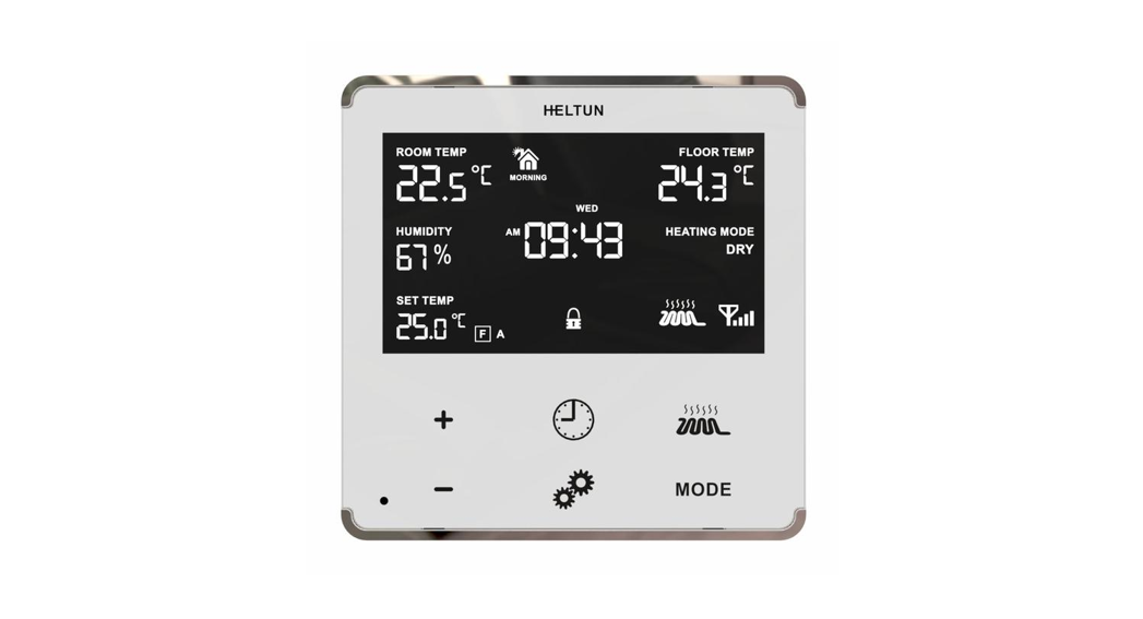
This is the user manual for HELTUN HE-HT01 Advanced Programmable Thermostat for Heating Systems. The HE-HT01 is elegantly designed and ‘Impossibly Smart’ providing wireless over-the-Internet control of your home’s heating system.The HE-HT01 is ‘Impossibly Thin’ on the wall yet packed with features to help you save energy while providing the ultimate comfort and convenience.Controls electric heating systemsThe HE-HT01 is designed to maintain the constant room and floor temperatures by providing sensors for both ambient and radiant floor heating systems. It controls electric heating systems like radiators, convection or electric fireplaces, plus boilers, and electric underfloor heating. Heating elements are directly controlled via a 16 Amp switch.Multiple built-in sensorsThe HE-HT01 has an LCD screen, six high sensitivity capacitive touch buttons, and two temperature sensors for monitoring: ambient air temperatures, and floor temperatures using the included external NTC sensor. It is also equipped with built-in sensors for humidity, illumination, and energy consumption. You can instantly access information from all sensors on the user-friendly display.Monitor all important information without even a touchThe at-a-glance display shows ambient air temperature, floor temperature, user setpoint, humidity level, current operating mode, time, day of the week, and status of the Z-Wave™ network & relay. Display brightness adjusts to ambient light conditions automatically making it always easy to read.Highly configurable with automatic safetyYou can select one of six operation modes with individual set points either manually, or by using a Z-Wave controller/gateway. As a safety measure, the HE-HT01 protects radiant floor systems from overheating by automatically switching off if the floor temperature reaches 40°C.Know how much energy you useThe HE-HT01 built-in Power Consumption System precisely monitors how much energy you used during any particular day, week, or month.Based on the latest Z-Wave platformThe HE-HT01 integrates a Z-Wave Plus™ v2 700 platform module allowing it to be used with Z-Wave home automation systems. The HE-HT01 supports Z-Wave ‘S0’ and ‘S2’ security protocols, SmartStart technology, and can be connected (“associated”) to other Z-Wave devices, such as relays, switches, etc.
Technical Specifications
- Front frame (on wall) dimensions: 89mm (H) х 89mm (W) х 9mm (D)
- Rear electronics package dimensions: 53mm (H) х 53mm (W) х 28mm (D)
- Materials: Tempered glass display/body, Flame retardant plastic
- 4 frame colors: White, Matte Black, Silver, Chrome
- 6 glass colors: White, Black, Yellow, Green, Red, Blue
- LCD: 72mm x 42mm (3.3 inch), black with white segments
- 6 capacitive-touch buttons
- Operating temperature: 0°С to +50°С
- Power supply: 85-265VAC 50Hz/60Hz, 24-48VDC
- Power consumption: 1W
- Maximum resistive load: 16А, 4000W @ 250VAC
- Relay switching with zero-cross technology
- Relay life time: 100.000 switches
- Internal ambient light sensor
- Internal temperature sensoro Measurement range: –30°C to +80°Co Accuracy: ±0.5°C
- Internal humidity sensoro Measurement range: 0% to 80%RHo Accuracy: ±3.0%RH
- External floor temperature sensoro NTC 10kΩo Measurement range: -30°C to +80°Co Accuracy: ±0.5°C
- Real-time energy consumption meter
- IP class: IP21
- Z-Wave Plus V2 SDK: V7.11
- Z-Wave module: ZGM130S
- Requires mounting to flush electrical junction box: round or square type – min. depth 40mm
Functions & Features
- Options for Inclusion/Exclusion to/from Z-Wave networko Non-Secureo S0 Secureo S2 Unauthorized, S2 Authorized with Key
- Association control of Z-Wave devices in the network
- 6 operational modes with individual temperature set points:o COM – Comfort/Heating Modeo ECO – Energy-saving Modeo VAC – Vacation/Away Modeo DRY – Floor Dry Modeo TIME – Schedule Modeo MAN – Manual Control Mode
- 4-time schedules for 7 days of the week:o Morningo Dayo Eveningo Night
- Temperature sensor selection:o Floor temperature onlyo Air temperature onlyo Floor + Air temperatureo Power regulator (Automatic ON/OFF timer)
- Can be used with different NTC-sensors (range: 1kΩ to 100kΩ)
- Periodic measurements from:o Internal temperature sensoro External floor temperature sensoro Internal humidity sensoro Internal ambient light sensoro Energy consumption meter
- Calibration of Internal Room Air Temperature Sensor
- Calibration of External NTC Temperature Sensor
- Temperature set intervals: 1.0°C to 37.0°C
- Temperature limiter: 40.0°C
- Temperature hysteresis selection range: 0.2°C to 10.0°C
- Relay output NO / NC mode
- HELTON Advanced Zero-Cross Relay switching technology
- Time format: 24 or 12 hours (AM/PM)
- LCD brightness:o Automatic adjustment (depending on ambient light)o Manual adjustment (10 levels).
- LCD standby mode (different brightness for active and inactive states)
- LCD backlight blinking function (for easy identification among other Z-Wave devices)
- Child lock mode (touch buttons lockout mode)
- Real-time and cumulative energy usage to 0.1kW accuracy
- Factory reset function
- SmartStart technology for a quick addition to Z-Wave networks
- Encrypted OTA (Over The Air) firmware update feature
Installation
HELTON recommends the HE-HT01 thermostat be installed by a licensed electrician in a manner that conforms to local regulations and building codes. Provide these instructions to the licensed electrician who is installing the HE-HT01.Note: It is not recommended to install the device in rooms with high humidity such as bathrooms or sauna.
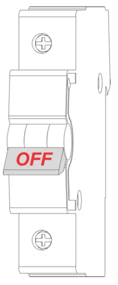
WARNING: Electrical power must be switched off during installation.
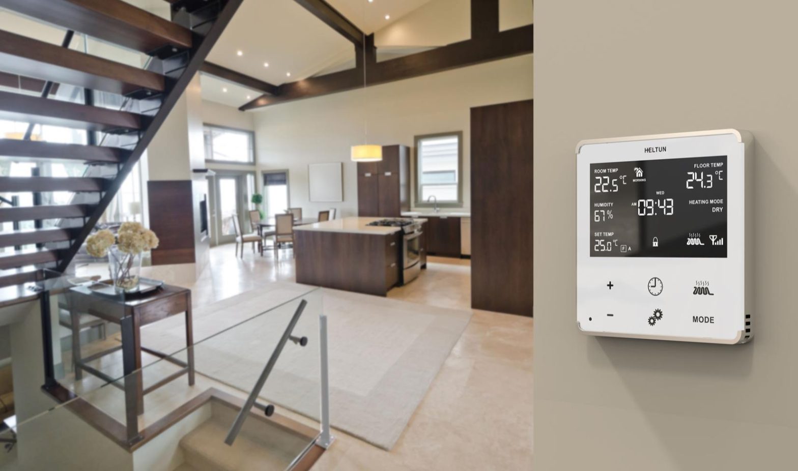
- Placement of the HE-HT01 is of utmost importance for proper operation and must be away from sunlight and sources of direct heat. We recommend installing the HE-HT01 approximately 1.5 meters above the floor.
- Remove the display unit and backplate of the HE-HT01 from the packaging.
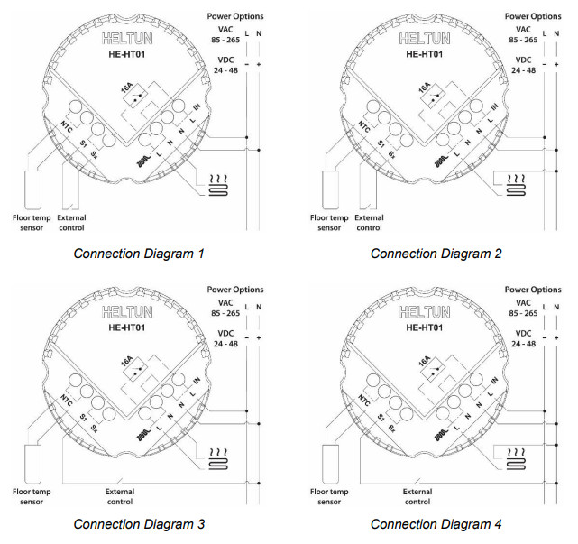
- FIRST ENSURE THE POWER IS OFF at the main circuit breaker, and then test the wires with a probe or multimeter to verify. Insert the power and heater wires to the correct HE-HT01 terminals by inserting a small Phillips-head screwdriver in the slot beneath each terminal to open. Follow the connection diagrams and instructions below:• Power wires: connect Line & Neutral wires to L & N terminals labeled “IN”• Heater wires: connect Line & Neutral wires to L & N terminals labeled with “heating element” graphic
 Note: HELTUN recommends installing cord terminals (electric wire ferrule) on the ends of wires before connecting them to the HE-HT01 (various colors terminals are included in the packaging).
 - If using the HE-HT01 for radiant floor heating, connect the NTC temperature sensor wire to the terminals labeled “NTC.” A 10 kΩ NTC sensor is included inside the HEHT01 packaging, but any NTC sensor can be used.Note: If an NTC sensor other than 10 kΩ is used, sensor Parameter value should be changed in the settings menu (Parameter 10 – FSr) – see “Settings Menu” section below.
- If you will be using an external device to select modes for the HE-HT01 (such as a security system), connect wires from the external device’s dry contacts according to connection diagrams 1 (or 2 or 3 or 4).Note: There could be an “EXT” label instead of “S1”, ”Sx”.
- Making sure the HE-HT01 backplate is oriented on the wall with the word “TOP” pointed upwards, secure the backplate onto the electrical junction box using the four provided screws (do not overtighten). Once the backplate is secured onto the wall, assemble the HE-HT01 display unit onto the backplate by first carefully aligning the two top snap connectors, and then gently pushing the entire display unit until it ‘snaps’ into position all the way around.
- Next, switch On the main power at the circuit breaker (see photo above). The HE-HT01 will start up showing the original default factory settings.
- Remove the clear protective film from the display unit and frame by pulling on the top right-hand orange color tabs.
 Note: HELTUN recommends installing cord terminals (electric wire ferrule) on the ends of wires before connecting them to the HE-HT01 (various colors terminals are included in the packaging).
Disassembly
- To disassemble, ENSURE POWER IS SWITCHED OFF at the main circuit breaker AND THE LCD SCREEN IS BLANK.
- To remove the HE-HT01 display unit grasp firmly at the bottom and pull backward while tilting outwards until all tabs disconnect.
- Remove screws from the backplate and disconnect the wires by inserting a small Phillips-head screwdriver into the slot beneath each wire to release.
Touch Panel Operation
The touch panel has six capacitive-touch buttons which require minimal pressure to operate.
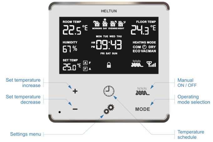
| Symbol: | Name: | Function: |
| + | Plus | Increase Set Point Temperature |
| – | Minus | Decrease Set Point Temperature |
| Time | Change Schedule | |
 |
Settings | Open Parameters Menu |
| Manual Heating | Manually Switch Heating Element ON or OFF | |
| MODE | Mode | Change the Operational Mode: (COM, TIME, DRY, ECO, VAC, MAN) |
The Plus “+” button will increase the Set Point temperature by 0.5°C with each touch. The Minus “–“ button will decrease Set Point temperature by the same 0.5°C. The SetPoint temperature is displayed in the bottom left corner of the LCD display under “SET TEMP.”
Note: The minimum SetPoint is 1.0°C and the maximum SetPoint is 37.0°C.
The HE-HT01 has two working modes: HEATING (switched On) and IDLE (switched Off). In HEATING mode, the heating element icon “ ![]() ” will appear near the right bottom corner of the display (to the left of the connectivity icon). The heating element icon will disappear when the HE-HT01 is in IDLE mode.
” will appear near the right bottom corner of the display (to the left of the connectivity icon). The heating element icon will disappear when the HE-HT01 is in IDLE mode.
Operation Modes
The current Operating Mode is shown on the middle, right of the LCD display under the label: “HEATING MODE.”The HE-HT01 has 6 Operating Modes:COM – Comfort Mode (Heat)TIME – Time Mode (Auto Changeover – schedule different Set Point per time and day)DRY – Floor Drying Mode (Dry Air)ECO – Power Efficient Mode (Energy Save Heat)VAC – Vacation Mode (Away)MAN – Manual Control Mode (Off)Change Modes by touching the “MODE” button (bottom right of display unit) until the desired Mode is reached. Each operating mode has individual temperature Set Points. The HE-HT01 will operate automatically depending on the current SetPoint indicated under the “SET TEMP” label on the LCD. To change the Set Point value, choose the desired mode and press Plus “+” button to increase, or the Minus “–” button to decrease the corresponded Set Point value. You may alternatively control Set Points through your Z-Wave gateway software.
COM – Comfort Mode (Heat)
This mode is recommended for maximum comfort. The factory default setpoint is 25.0°C.Note: In your Z-Wave gateway this mode will be shown as “Heat”.
TIME – Temperature Schedule Mode (Auto Changeover)
The Temperature Schedule (TIME) Mode can adjust home temperatures automatically to align with your personal habits, saving energy while you are away, and maintaining a comfortable temperature while you are active at home.
The HE-HT01 can have different Schedules for Morning, Daytime, Evening, and Night. For example, the “Morning” Schedule could be set to 22.0°C starting at 6:00. The “Day” Schedule could then be set to 17.0°C at 9:00 when everyone has gone to work or school, and so on.Here are recommended Scheduled Set Points for heating during the work week – you may wish to change these on weekends depending on your family’s schedule (see example below):

| ScheduleMode | SetTime | Set Point Temperature |
| Morning | 6:00 (6:00 AM) | 22°C |
| Day | 9:00 (9:00 AM) | 17°C |
| Evening | 18:00 (6:00 PM) | 21°C |
| Night | 23:00 (11:00 PM) | 18°C |
To set up the time and temperature for each Schedule press and hold the Clock “ ![]() ” button for three seconds. The display will change to the Time menu.
” button for three seconds. The display will change to the Time menu.
To set up the start time for each Schedule, choose the Schedule by pressing the Clock “ ![]() ” button then adjust the time by pressing the Heating Element “
” button then adjust the time by pressing the Heating Element “ ![]() ” button to increase, or the “MODE” button to decrease. Press the Clock “
” button to increase, or the “MODE” button to decrease. Press the Clock “ ![]() ” button again to advance to the next schedule and set the time for all four: Morning, Day, Evening & Night.
” button again to advance to the next schedule and set the time for all four: Morning, Day, Evening & Night.
To choose the temperature Set Points for each Schedule, choose the day of the week by pressing the Gear “ ![]() ” button, then choose the Schedule by pressing the Clock “
” button, then choose the Schedule by pressing the Clock “ ![]() ” button and adjust the temperature Set Point up or down by pressing the Plus “+” or Minus “–“ buttons. Do this action for each day of the week.Note: Time for all four Schedules (Morning, Day, Evening, & Night) are the same for all seven days of the week.Note: TIME mode will work properly only if the correct current time and date have been set. The time can be automatically corrected from your Z-Wave gateway if the Parameter 19 value is set to 1. Or it can be set manually in Parameters 21, 22, and 23 in the Settings Menu (see below).Note: While in TIME mode, the temperature Set Point (under the label “SET TEMP” on the LCD) will be automatically changed depending on the Schedule. The Set Point can be adjusted up or down manually at any time, but it will be effective only until the next Schedule.
” button and adjust the temperature Set Point up or down by pressing the Plus “+” or Minus “–“ buttons. Do this action for each day of the week.Note: Time for all four Schedules (Morning, Day, Evening, & Night) are the same for all seven days of the week.Note: TIME mode will work properly only if the correct current time and date have been set. The time can be automatically corrected from your Z-Wave gateway if the Parameter 19 value is set to 1. Or it can be set manually in Parameters 21, 22, and 23 in the Settings Menu (see below).Note: While in TIME mode, the temperature Set Point (under the label “SET TEMP” on the LCD) will be automatically changed depending on the Schedule. The Set Point can be adjusted up or down manually at any time, but it will be effective only until the next Schedule.
Note: In your Z-Wave gateway this mode will be shown as “Auto Changeover”.DRY – Fast Floor Drying Mode (Dry Air)This mode is recommended for use if a high floor temperature is required for a limited period of time. For example, after washing the floor. By choosing DRY Mode, the HE-HT01 will increase the temperature to the selected Set Point for the time specified in the “Dry Time” Parameter (Parameter 25). A time range of 5 to 90 minutes can be set. As the Dry Time passes, the HE-HT01 will automatically change to the Mode set in Parameter 26.
To change the Dry Time Parameter, open the “Settings Menu” by pressing the Gears “ ![]() ” button for three seconds. Use the “
” button for three seconds. Use the “![]() ” and “MODE” buttons to scroll up and down through the menu to Parameter 25. Then use buttons “+” and “–” to increase or reduce the Dry Time setting (in minutes).
” and “MODE” buttons to scroll up and down through the menu to Parameter 25. Then use buttons “+” and “–” to increase or reduce the Dry Time setting (in minutes).
To choose the mode to revert to after Dry Time has elapsed (while still in the Settings Menu), press the “ ![]() ” or “MODE” button to select Parameter 26, then use buttons “+” and “–” to choose the desired Mode as follows:
” or “MODE” button to select Parameter 26, then use buttons “+” and “–” to choose the desired Mode as follows:
| Mode: | Value: | Notes: |
| COM | 1 | This is the factory default for revert after DRY Mode (Parameter 8) |
| TIME | 2 | |
| DRY | n/a | You cannot revert to DRY Mode. |
| ECO | 4 | |
| VAC | 5 | |
| MAN | 6 | If MAN Mode is chosen, the HE-HT01 will select an IDLE state |
Note: Factory defaults for Dry Time are: 30 minutes at 30.0°C.Note: In your Z-Wave gateway this mode will be shown as “Dry Air”.
ECO – Energy Saving Mode (Energy Save Heat)
This Mode can be used if lower temperature and energy consumption is desired. It can also be used at night or when away from all or part of the property for a length of time. The factory default ECO SetPoint is 20.0°C.Note: In your Z-Wave gateway this mode will be shown as “Energy Save Heat”.
VAC – Vacation Mode (Away)
Use Vacation Mode when you are planning to be away from home for some period. The factory default temperature SetPoint is 15.0°C.Note: The minimum set point for each mode is 1.0°C and the maximum set point is 37.0°C.Note: In your Z-Wave gateway this mode will be shown as “Away”.
MAN – Manual Control Mode (Off)
In this Mode the HE-HT01 schedules are disabled and the heating state is switched On & Off manually by pressing the Heating Element “ ![]() ” button.Note: When in Manual Control Mode the “SET TEMP” will indicate “OFF”.Note: In your Z-Wave gateway this mode will be shown as “Off”.
” button.Note: When in Manual Control Mode the “SET TEMP” will indicate “OFF”.Note: In your Z-Wave gateway this mode will be shown as “Off”.
Child Lock (LOC)
The Child Lock feature allows you to disable the HE-HT01 touch buttons temporarily. To activate the Child Lock Mode, press and hold the Heating Element “ ![]() ” button for five seconds until the Lock Icon “
” button for five seconds until the Lock Icon “ ![]() ” appears in the bottom center of the display. To deactivate the Child Lock, press the Heating Element “
” appears in the bottom center of the display. To deactivate the Child Lock, press the Heating Element “ ![]() ” button until the Lock Icon “
” button until the Lock Icon “ ![]() ” disappears.
” disappears.
Factory Reset (RES)
By pressing and holding the “MODE” button for six seconds, the HE-HT01 will enter Factory Reset Mode, displaying “REs” in the left bottom corner, “y” in the top left corner, and “n” in the top right corner. Press the Plus “+” button to revert to factory settings or the Heating Element “ ![]() ” button to cancel. The factory reset will change all the Parameters to their original factory default values (including Z-Wave frequency) and will also Exclude the device from any Z-Wave network.Note: Please use this procedure only when the network primary controller is missing or otherwise inoperable.
” button to cancel. The factory reset will change all the Parameters to their original factory default values (including Z-Wave frequency) and will also Exclude the device from any Z-Wave network.Note: Please use this procedure only when the network primary controller is missing or otherwise inoperable.
Z-Wave Network
The HE-HT01 may be operated in any Z-Wave network with other Z-Wave certified devices from other manufacturers.The HELTUN HE-HT01 will act as a ‘repeater’ for other devices regardless of manufacturer or brand to increase the reliability of the overall network.
Adding to Z-Wave network
To add HE-HT01 into a Z-Wave network (inclusion), do the following:
- Enter “SETTINGS” Mode by pressing and holding the Gear “ ” button for three seconds.
- If you need to change the device Z-Wave frequency, scroll the menu to “Parameter 1 – ГEg” using the Heating Element “ ” button to scroll up, and the “MODE” button to scroll down. Choose the frequency using the “+” or “–” buttons.
- Scroll menu to “Parameter 2 – nEt”. The current state of the network will be displayed in the Parameter Value position (upper right). It should display “EСL”.Note: If “InC” is displayed, the HE-HT01 must first be Excluded from an existing Z-Wave network (see “Removing from Z-Wave network” below).
- Start the Inclusion Mode from the gateway/controller.
- On the HE-HT01 in Parameter 2 press the Plus “+” button to start the Inclusion process.
- Note that lines will be moving in the Parameter value position (upper right).
- “InC” should appear at the Parameter Value position (and the “ ” icon on the main display bottom right corner) if Inclusion was successful.
- If “EСL” or “Err” is on Value position (or “ ” icon on the main display bottom right corner), the HE-HT01 Inclusion was not successful (try repeating steps 4-7).
Removing from Z-Wave network
To remove HE-HT01 from a Z-Wave network (exclusion), do the following:
- Enter “SETTINGS” Mode by pressing and holding the Gear “ ” button for three seconds.
- Scroll menu to “Parameter 2 – nEt” using the Heating Element “ ” button to scroll up, and the “MODE” button to scroll down.
- The current state of the network will display in the Parameter Value position (upper right). It should display “InC”.Note: If “EСL” is displayed, the HE-HT01 is already Excluded.
- Start the Exclusion Mode from the gateway/controller.
- Press the Minus “–” button in the HE-HT01 Parameter 2 to start the Exclusion process Note that lines will be moving in the Parameter value position (upper right).
- “EСL” should appear in the value position (and “ ” icon in the bottom right corner of the main display) if the Exclusion was successful.
- If “InC” or “Err” in value position (or “ ” icon in the bottom right corner of the main display) are displayed, repeat the Exclusion process.
Note: If the HE-HT01 has previously been part of a Z-Wave network and not Excluded since Inclusion is not possible without first performing an Exclusion or Factory Reset procedure.Note: If the HE-HT01 is included in the Z-Wave network the antenna icon will appear in the bottom right corner of the main screen with signal strength bars “ ![]() ”.
”.
Security
S0, S2 unauthorized, and S2 authorized Inclusion Modes are supported. If you use the S2 authorized Inclusion Mode the security key should be used during the inclusion process. The security key is the first 5 digits of DSK (device DSK is printed on the HE-HT01 back panel plus on the Security Card included in the packaging).Note: Be sure to save this key. Without the key, it is impossible to perform an inclusion in S2 authorized mode.

SmartStart
SmartStart-enabled products can be added to a Z-Wave network by scanning the Z-Wave QR Code shown on the product with gateways/controllers that allow SmartStart inclusion. In this case, no further action will be required and the SmartStart product will be added automatically within ten minutes of being turned on in the vicinity of a network.
To add the HE-HT01 to the Z-Wave network using SmartStart:
- Input the thermostat DSK to the controller’s Node Provisioning List (or scan the QR code).
- Power on the device.
- Wait for the adding process to complete.
- Successful adding will be confirmed by displaying the Antenna with signal strength bars “ ” icon in the bottom right corner of the main screen.
Note: The device DSK and QR code are printed on the HE-HT01 back panel plus on the manual included in the HE-HT01 packaging.
Firmware OTA Update
To wirelessly update the HE-HT01 firmware, follow these steps:
- Check the current firmware version (Parameter 3 in the settings).
- Start the process from the gateway/controller.
- Download the firmware that corresponds to the HE-HT01.
- Set the main controller in Firmware OTA (“over-the-air”) Update Mode (see the gateway/controller manual).
- As soon as the Firmware update begins, the “LOAd” text will be displayed on the screen (this will take a few minutes).
- When the Firmware has updated, “and” will display on the screen for three seconds and the HE-HT01 will reboot.
- When the update has been completed, the HE-HT01 will return to normal operation.
- If desired, verify the update was successful by checking the software version in Parameter 3 of the Settings Mode.
Z-Wave Plus V2 Specifications
Generic Device Class: GENERIC_TYPE_THERMOSTATSpecific Device Class: SPECIFIC_TYPE_THERMOSTAT_GENERAL_V2Supported Command Classes
| Command Class | Version | Required Security Class |
| Z-Wave Plus Info | V2 | none |
| Association | V2 | highest granted (S2 Authenticated, S2 Unauthenticated or SO) |
| Association Group Info | V3 | highest granted (S2 Authenticated, S2 Unauthenticated or SO) |
| Multi-Channel Association | V3 | highest granted (S2 Authenticated, S2 Unauthenticated or SO) |
| Thermostat Operating State | V1 | highest granted (S2 Authenticated, S2 Unauthenticated or SO) |
| Thermostat Mode | V3 | highest granted (S2 Authenticated, S2 Unauthenticated or SO) |
| Thermostat Setpoint | V3 | highest granted (S2 Authenticated, S2 Unauthenticated or SO) |
| Sensor Multilevel | V11 | highest granted (S2 Authenticated, S2 Unauthenticated or SO) |
| Meter | V5 | highest granted (S2 Authenticated, S2 Unauthenticated or SO) |
| Clock | V1 | highest granted (S2 Authenticated, S2 Unauthenticated or SO) |
| Transport Service | V2 | none |
| Security 0 | V1 | none |
| Security 2 | V1 | none |
| Version | V3 | highest granted (S2 Authenticated, S2 Unauthenticated or SO) |
| Manufacturer Specific | V2 | highest granted (S2 Authenticated, S2 Unauthenticated or SO) |
| Device Reset Locally | V1 | highest granted (S2 Authenticated, S2 Unauthenticated or SO) |
| Powerlevel | V1 | highest granted (S2 Authenticated, S2 Unauthenticated or SO) |
| Supervision | V1 | none |
| Indicator | V3 | highest granted (S2 Authenticated, S2 Unauthenticated or SO) |
| Configuration | V4 | highest granted (S2 Authenticated, S2 Unauthenticated or SO) |
| Application Status | V1 | none |
| Firmware Update Meta Data | V5 | highest granted (S2 Authenticated, S2 Unauthenticated or SO) |
| Basic | V2 | highest granted (S2 Authenticated, S2 Unauthenticated or SO) |
Meter Command Class:
| Meter Type | Scale | Rate Type | Precision | Size |
| Electric [0x01] | Electric_kWh [0x00] | Import [0x01] | 2 | 4 |
| Electric [0x01] | Electric_W [0x02] | Import [0x01] | 0 | 2 |
| Electric [0x01] | Electric_V [0x04] | Import [0x01] | 0 | 2 |
Associations
Association enables the HE-HT01 to control other Z-Wave devices over the network. Association Group may control other devices from different brands and/or manufacturers. The HE-HT01 has two association groups:Group 1 – “Lifeline”: reports the full state of the device and is used to communicate with the Z-Wave gateway. Max supported nodes: 1Note: It is not recommended to modify this group.Group 2 – “Basic Set On/Off: Relay”: is assigned to the HE-HT01 operating state. It sends a Basic Set command with value 0 (Off) when it goes to the IDLE state and sends 255 (ON) when it goes into HEATING state. Max supported nodes: 1
To enter the Settings Menu, press and hold the Gear “ ![]() ” button for three seconds. The abbreviated Parameter Name will be displayed in the bottom left corner of the LCD. The top left corner will display the Parameter Number. And the top right corner will display the Parameter Value.
” button for three seconds. The abbreviated Parameter Name will be displayed in the bottom left corner of the LCD. The top left corner will display the Parameter Number. And the top right corner will display the Parameter Value.
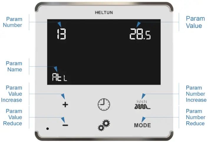
To scroll through the menu, press the Heating Element “ ![]() ” button to go up and the “MODE” button to go down.To change the Parameter value, press the Plus “+” or Minus “–” buttons.To leave the Settings Menu press and hold the “
” button to go up and the “MODE” button to go down.To change the Parameter value, press the Plus “+” or Minus “–” buttons.To leave the Settings Menu press and hold the “ ![]() ” button for 3 seconds or just wait. If no action is detected for 20 seconds the display will automatically revert to the main display mode.
” button for 3 seconds or just wait. If no action is detected for 20 seconds the display will automatically revert to the main display mode.
All configuration parameters are accessed through Z-Wave COMMAND_CLASS_CONFIGURATION
| Group | Number | Name | Description | DefaultValue | Value Range |
| Z-Wave | 1 | [Eg | Frequency Region | EU: EuropeUS: USAAU: AustraliaHO: Hong KongIn: IndiaIL: IsraelRU: RussiaCn: ChinaJP: JapanOr: Korea | |
| 2 | nEt | Inclusion / Exclusion Mode | InC, ECL | ||
| Version | 3 | HS | Hardware and Firmware Versions | Read Only | |
| Load Power | 4 | LPc | Energy Consumption, kWH Load Power, kW | Read Only | |
| Consumption | |||||
| Display | 5 | dbr | Display brightness control | 0 | 0, 1 … 10 |
| Brightness | |||||
| Touch | 6 | tCH | Touch button sensitivity:1 = Lowest sensitivity, 10 = Highest sensitivity, | 6 | 1…10 |
| Sensitivity | |||||
| Inputs / | 7 | 1EL | Relay output NO or NC mode | 0 | 0, 1 |
| 8 | All | External input mode | 0 | 0, 1, 2, 3 | |
| Outputs | |||||
| 9 | In2 | Mode number for External Input action: 1 = COM, 2 = TIME, 3 = DRY, 4 = ECO, 5 = VAC, 6 = MAN (Off#) | 6 | 1, 2, 3, 4, 5, 6 | |
| Configuration | |||||
| 10 | FSr | Floor Sensor Resistance, kΩ | 10 | 1…100 | |
| Temperature | 11 | SEn | Source Sensor:1 = A, 2 = AF, 3 = F, 4 = FA, 5 = t, 6 = tA, 7 = tF | 3 | 1, 2, 3, 4, 5, 6, 7 |
| 12 | AtL | Air Temperature Minimum | 21 | 1.0°C … 36.0°C | |
| 13 | AtH | Air Temperature Maximum | 27 | 2.0°C … 37.0°C | |
| 14 | FtL | Floor Temperature Minimum | 18 | 1.0°C … 36.0°C | |
| Configuration | |||||
| 15 | FtH | Floor Temperature Maximum | 32 | 2.0°C … 37.0°C | |
| 16 | FTC | Floor Temperature Calibration. | 0 | -10°C … 10°C | |
| 17 | ATC | Air Temperature Calibration. | 0 | -10°C … 10°C | |
| 18 | Sy | Temperature Hysteresis. | 0.5 | 0.2°C … 10.0°C | |
| Time | 19 | TCR | Time correction by the controller | 1 | 0, 1 |
| 20 | two | Time Format: 0=24 hour, 1=12 hour (AM/PM) | 0 | 0, 1 | |
| 21 | dAy | Day of the Week | 1 | 1, 2, 3, 4, 5, 6, 7 | |
| 22 | tIA | Time Manual Adjustment – Hour: Minutes | 0 | 00:00 … 23:59 | |
| Configuration | |||||
| 23 | tOn | Time Regulation ON time, min | 30 | 10…240 | |
| 24 | tOF | Time Regulation OFF time, min | 30 | 10…240 | |
| 25 | dr1 | Dry Time, min | 30 | 5…90 | |
| 26 | dr2 | Mode to revert to after completion of Dry mode: | 1 | 1, 2, 4, 5, 6 |
Z-Wave
Parameter 01 (“ГEg”) – Frequency RegionThe HE-HT01 has a Z-Wave 700 series chip inside which allows using of the device in different Z-Wave frequencies. If there is a need to use the device in a frequency different from the factory default, change the value of this Parameter according to the frequency list below. Modification is possible only while the HE-HT01 is not included in to Z-Wave network. While the device is included, the Antenna Icon “![]() ” is shown at the bottom right corner of the LCD main screen, and modification of this Parameter is disabled.To navigate through different values from the menu use the Plus “+” and Minus “–“ buttons. After the Frequency Region has been selected (according to the frequency list below), hold the Clock “
” is shown at the bottom right corner of the LCD main screen, and modification of this Parameter is disabled.To navigate through different values from the menu use the Plus “+” and Minus “–“ buttons. After the Frequency Region has been selected (according to the frequency list below), hold the Clock “ ![]() ” button for 3 seconds to save the Parameter value. The device will reboot for the new settings to take effect.Note: The factory default frequency differs depending on which region the device was intended for sale in. Check the factory default frequency on the device plate or on the packaging.Note: Do not change this Parameter value if there is no special need.Note: If change the value of this Parameter through the Z-Wave network, the frequency change will be applied only after removing the device from the Z-Wave network (the device will automatically reboot)․Note: The change of this parameter will result in an inability to control the device if the device was included in the controller/gateway which supports only one frequency.Note: Resetting the device to factory default settings will revert the frequency to the factory default value.Note: In most of the countries it is not allowed to use a frequency different from the frequency intended for that country.
” button for 3 seconds to save the Parameter value. The device will reboot for the new settings to take effect.Note: The factory default frequency differs depending on which region the device was intended for sale in. Check the factory default frequency on the device plate or on the packaging.Note: Do not change this Parameter value if there is no special need.Note: If change the value of this Parameter through the Z-Wave network, the frequency change will be applied only after removing the device from the Z-Wave network (the device will automatically reboot)․Note: The change of this parameter will result in an inability to control the device if the device was included in the controller/gateway which supports only one frequency.Note: Resetting the device to factory default settings will revert the frequency to the factory default value.Note: In most of the countries it is not allowed to use a frequency different from the frequency intended for that country.
Frequency list for different regions:
| 0: EU (868.4 MHz, 869.85 MHz)1: US (908.4 MHz, 916.0 MHz)2: AU (919.8 MHz, 921.4 MHz)3: HO (919.8 MHz)4: In (865.2 MHz) | 5: IL (916.0 MHz)6: RU (869.0 MHz)7: Cn (868.4 MHz)8: JP (922.5 MHz, 923.9 MHz, 926.3 MHz)9: Or (920.9 MHz, 921.7 MHz, 923.1 MHz) |
The full list of Z-Wave global regions where Z-Wave works are available at the Z-Wave Global Regions SiLabs page.
Parameter 02 (“nEt”) – Inclusion / Exclusion to/from Z-Wave NetworkIf the HE-HT01 is included in a Z-Wave network, the Antenna Icon “ ![]() ” will be shown in the LCD main screen and “InC” will be indicated as this Parameter value. If it is not included in the network, Antenna Icon “
” will be shown in the LCD main screen and “InC” will be indicated as this Parameter value. If it is not included in the network, Antenna Icon “ ![]() ” will be shown in the main screen, and the Parameter value will be “ECL”. To include or exclude the HE-HT01 into or from your Z-Wave network, activate Inclusion or Exclusion Mode on your gateway, then go to Parameter 02 in the Device Menu and press the Plus “+” button for Inclusion, or Minus “–” for Exclusion. For more details see the Z-Wave Network section of this manual.Note: Through the Z-Wave network this Parameter is read-only and the modification is disabled.
” will be shown in the main screen, and the Parameter value will be “ECL”. To include or exclude the HE-HT01 into or from your Z-Wave network, activate Inclusion or Exclusion Mode on your gateway, then go to Parameter 02 in the Device Menu and press the Plus “+” button for Inclusion, or Minus “–” for Exclusion. For more details see the Z-Wave Network section of this manual.Note: Through the Z-Wave network this Parameter is read-only and the modification is disabled.
Hardware & Software Versions
Parameter 03 (“HS”) – Hardware and Software VersionsThis Parameter allows you to manually check the hardware and firmware versions of the HE-HT01 directly from the device screen. Display information follows this format: Firmware Major Version – displayed at the Hours position, Minor Version – displayed at the Minutes position. Hardware version – displayed at the top right corner at the Floor sensor position.Through the Z-Wave network the Parameter returns the value in the format XXYYZZ, where XX is Hardware Version, YY is Firmware Major Version and ZZ is Firmware Minor version.Note: This Parameter is read-only in the menu and through the Z-Wave network.
Power and Energy Consumption
HE-HT01 monitors Real-Time and Cumulative power Energy Consumption and Voltage using an advanced microcontroller technology which assures maximum accuracy (±1% for loads greater than 1000W).Real-Time Consumption, Cumulative Consumption, and network Voltage are periodically reported to the Z-Wave controller (according to the Parameters 141 and 142), and are also accessible from the device menu:
Parameter 04 (“LPc”) – Energy Consumption valuesThis Parameter allows you to check the Cumulative and Real-Time Energy Consumption of the connected load. Display information follows this format: Total Cumulative Consumption – displayed at the time position in kWh, Real-Time Consumption – displayed at the top right corner at the Floor sensor position in kW. Through the Z-Wave network, this Parameter returns the Total Cumulative Consumption value in kW.Note: This Parameter in read-only.
Resetting Cumulative Consumption memory:The HE-HT01 Thermostat allows to erase of stored Consumption Data through the Z-Wave network or manually through the device menu.
Using the device menu:
- Go to the device settings by holding the Settings “ ” button for 3 seconds
- Go to the Parameter 04
- Press and hold the “+” button for 3 seconds.
Using the Z-Wave network:
- Make sure the device is powered.
- Include the device in to Z-Wave gateway/controller
- Reset memory consumption data using Reset Command in COMMAND_CLASS_METER (see the controller’s manual).
Note: Turning the device main power off/on will not erase the consumption data as it is stored in nonvolatile memory
Display Brightness
The HE-HT01 has two brightness levels for its LCD display: Active Level – when any button is pressed the display becomes brighter, and Inactive Level – after 20 seconds of inactivity the display becomes less bright. The actual display brightness may be adjusted (see below).
Parameter 05 (“dbr”) – Display Brightness ControlThe HE-HT01 can adjust its display brightness automatically depending on the illumination of the ambient environment and also allow to control it manually. Set the Parameter value to 0 to activate the Automatic Brightness Control or set from value 1 (lowest brightness) to 10 (highest brightest) for Manual Control. The factory default value is 0.Note: The environment illumination is displayed in the menu of this Parameter (in the time position) and can be checked at any time via a Z-Wave gateway.
Touch Sensitivity
Parameter 06 (“tCH”) – Touch Sensor Sensitivity ThresholdThis Parameter allows the device Touch Button Sensitivity Threshold to be adjusted from level 1 (low sensitivity) to 10 (high sensitivity). The factory default value is 6.Note: Setting the sensitivity too high can lead to false touch detection. We recommend not changing this Parameter unless there is a special need to do so.
Input & Ouput Configurations
Parameter 07 (“ГEL”) – Relay output mode (NO / NC)This Parameter determines the type of load connected to the device relay output. The output type can be NO – normal open (no contact/voltage switch the load OFF) or NC – normal close (output is contacted / there is a voltage to switch the load OFF). Choose the value 0 if NO contact type is required or value 1 if NC type is required.The factory default value is 0.Parameter 08 (“In1”) – External Input ModeThe HE-HT01 can be connected to the dry output contacts of an external device (i.e. security system) to control the Thermostat operating modes depending on the state of the external device.See Connection Diagrams on page 5 of this manual.Note: In case of using “Connection Diagram 3 or 4”, it is MANDATORY to connect S1 terminal to the same wire connected to terminal N on the device (labeled as “IN”) through dry contacts of an external device (like wall switch).If Parameter value = 0 no action will be taken (the input state changes will be ignored by the Thermostat logic).If Parameter value = 1 the external input will operate in “Toggle Switch” mode: if the external input is shorted (with Sx or N) the Thermostat switches to the operating mode selected in the Parameter 09 and switches to MAN mode with the IDLE state (OFF) when the external input is open (released).If Parameter value = 2 the external input will operate in “Toggle Switch Reverse” mode: if the external input is shorted the Thermostat switches to MAN mode with the IDLE state (OFF) and switches to the operating mode selected in Parameter 09 when the input is open.If Parameter value = 3 the external input will operate in “Push Button (Momentary Switch)” mode: each press of a button (shorten of the input) will consistently change the mode to mode selected in the Parameter 09 then to MAN mode with IDLE state.Note: The Mode switch is blocked when the Source Sensor (Parameter 11) is: “t” (value = 5), “tA” (value = 6) or “tF” (value = 7). Factory default value is 0.
Parameter 09 (“In2”) – Operating Mode for External Input ActionThis Parameter allows selection of which Operating Mode the HE-HT01 should revert to if the external input S1 is shortcircuited.1 = COM, 2 = TIME, 3 = DRY, 4 = ECO, 5 = VAC, 6 = MAN mode with IDLE (Off) state. Factory default value is 6.Parameter 10 (“FSr”) – Floor Sensor ResistanceIf the external floor NTC temperature sensor is used it is necessary to select the correct resistance value in Ohms (Ω) of the sensor. The selection range is 1 to 100 kiloOhms (kΩ). One 10kΩ NTC floor temperature sensor is included in the HE-HT01 package with a 3-meter connection wire. The factory default value is 10kΩ.Note: If the floor sensor is disconnected or damaged “– –” will be shown on the LCD display under the FLOOR TEMP label.
Temperature Configurations
Parameter 11 (“SEn”) – Source SensorThe HE-HT01 has seven Regulation Modes based on different sensors values. Use the Plus “+” and Minus “–” buttons to choose follow modes:
| Value throughZ-Wave | Value onScreen | Source Sensor |
| 1 | A | Air sensor |
| 2 | AF | Air sensor + Floor sensor |
| 3 | F | Floor sensor |
| 4 | FA | Floor sensor + Air sensor |
| 5 | t | Time regulator |
| 6 | tA | Time regulator + Air sensor |
| 7 | tF | Time regulator + Floor sensor |
- A – Air sensor: Regulation (heating control) is based on the SETPOINT applied to the internal room air temperature sensor.
- AF – Air sensor plus floor sensor: Regulation is based on SET POINT applied to the internal room temperature sensor but also controlled by the floor temperature sensor ensuring that the floor temperature remains within the set limits. The lower floor temperature limit is specified in Parameter 14 (FtL) and the high-temperature limit in Parameter 15 (FtH).
- F – Floor sensor: Regulation is based on the SET POINT applied to the external floor temperature sensor.
- FA – Floor sensor plus air sensor: Regulation is based on SET POINT applied to the external floor sensor but is also controlled by the internal air temperature sensor ensuring that the room temperature remains within the set limits. The lower air temperature limit is specified in Parameter 12 (ATL) and the higher temperature limit in Parameter 13 (AtH).
- t – Time regulator: Regulation is based on the time settings for heating which will be ON during the time in Parameter 23 (tOn) and then OFF during the time in Parameter 24 (tOf). This cycle will be repeated constantly.
- tA – Time regulator + Air sensor: Regulation is based on the time set by Parameters 23 and 24 but also controlled by the internal air temperature sensor ensuring that the room temperature remains within the set limits. The air temperature limits are specified in Parameters 12 and 13.
- tF – Time regulator + Floor sensor Parameters: Regulation is based on the time set by Parameters 23 and 24 but also controlled by the floor temperature sensor ensuring that the floor temperature remains within set limits. The floor temperature limits are specified in Parameters 14 and 15.
Example:In FA mode the SETPOINT is set to 30°C, it is set to 24°C and it is set to 27°C:a) If the floor temperature is lower than 30°C and the room temperature is lower than 27°C the HE-HT01 will operate in HEATING mode.b) If the floor temperature is higher than 30°C or the room temperature is higher than 27°C then the HE-HT01 will enter IDLE mode which switches off the heater.c) If the room temperature is lower than 24°C the Heating Thermostat will operate in HEATING mode even though the floor temperature is higher than 30°C.d) If the room temperature is higher than 27°C the Heating Thermostat will enter IDLE mode even though the floor temperature is lower than 30°C.The factory default value is 3 (F).
Caution: Be careful when setting the lower limitation — Parameters 12 (ATL) and 14 (FtL) — to be sure that the value is not too high, and it can be reached. Otherwise, the HE-HT01 will stay always in HEATING mode.Note: For safety reasons, the HE-HT01 will enter IDLE mode if the floor temperature reaches 40°C despite Parameter settings.Note: If there is no floor sensor installed, or it becomes damaged (indicated by ” – – “ in the “FLOOR TEMP”), the regulation mode (A) will be automatically selected as the source sensor. This can only be changed to “t” or “tA”. If one of the source sensors is selected from the list “F”, “FA”, “AF” or “to”, the message “Error” will appear on the screen.
Parameter 12 (“ATL”) – Air Temperature Minimum (Lowest level)This Parameter is the room temperature low limit – reading the internal temperature sensor. This only comes into effect if “FA” or “tA” are selected as the source sensor in Parameter 11. The Parameter value can be selected from 1.0°C to 36.0°C. Through the Z-Wave network the value of this Parameter should be x10, e.g. for 22.5°C set the value 225. The factory default value is 21°C (210 through Z-Wave network).Note: The AtL value cannot be higher than (AtH – 1)°C.
Parameter 13 (“AtH”) – Air Temperature Maximum (Highest level)This Parameter is the room temperature high limit – reading the internal temperature sensor. This only comes into effect if “FA” or “tA” are selected as the source sensor in Parameter 11. The Parameter value can be selected from 2.0°C to 37.0°C. Through the Z-Wave network the value of this Parameter should be x10, e.g. for 22.5°C set the value 225. The factory default value is 27°C (270 through the Z-Wave network).Note: The cash value cannot be lower than (ATL + 1)°C.
Parameter 14 (“FtL”) – Floor Temperature Minimum (Lowest level)This Parameter is the floor temperature low limit – reading the external NTC temperature sensor. It only comes into effect if AF or tF are selected as the source sensor in Parameter 11. The Parameter value can be selected from 1.0°C to 36.0°C.Through the Z-Wave network the value of this Parameter should be x10, e.g. for 22.5°C set the value 225. The factory default value is 18°C (180 through Z-Wave network).Note: The FtL value cannot be higher than (FtH – 1)°C.
Parameter 15 (“FtH”) – Floor Temperature Maximum (Highest level)This Parameter is the floor temperature high limit – reading the external NTC temperature sensor. It only comes into effect if AF or tF are selected as the source sensor in Parameter 11. The Parameter value can be selected from 2.0°C to 37.0°C.Through the Z-Wave network the value of this Parameter should be x10, e.g. for 22.5°C set the value 225. The factory default value is 32°C (320 through Z-Wave network).Note: The FtH value cannot be lower than (FtL + 1)°C.
Parameter 16 (“FTC”) – Floor Temperature CalibrationThis Parameter defines the offset value for floor temperature. If the external floor temperature sensor is not calibrated properly, then manual calibration can be made by adjusting the values up to ±10.0°C. This value will be added or subtracted from the floor temperature sensor reading. Through the Z-Wave network, the value of this Parameter should be x10, e.g. for 1.5°C set the value 15. The factory default value is 0.
Parameter 17 (“ATC”) – Air Temperature CalibrationThis Parameter defines the offset value for room air temperature. If the internal air temperature sensor is not correctly calibrated, then manual calibration can be made by adjusting the values up to ±10°C. This value will be added or subtracted from the internal air temperature sensor reading. Through the Z-Wave network, the value of this Parameter should be x10, e.g. for 1.5°C set the value 15. The factory default value is 0.
Parameter 18 (“HyS”) – Temperature Hysteresis (HyS)This parameter defines the hysteresis value for temperature control. The HE-HT01 will stabilize the temperature with selected hysteresis. For example, if the SETPOINT is set for 25°C and HYSTERESIS is set for 0.5°C the HE-HT01 will change the state to IDLE if the temperature reaches 25.0°C, but it will change the state to HEATING if the temperature becomes lower than 24.5°C. The hysteresis can be changed from 0.2°C to 10.0°C range. Through the Z-Wave network, the value of this Parameter should be x10, e.g. for 1.2°C set the value 12. The factory default value is 0.5°C (5 through the Z-Wave network).
Time Configurations
Parameter 19 (“TCR”) – Time Correction by Main ControllerIf this Parameter value = 1 and the HE-HT01 is connected to a Z-Wave gateway, the HE-HT01 time and day will be periodically polled and corrected from the gateway. To switch off auto-correction set the Parameter value to 0. The factory default value is 1.Parameter 20 (“the”) – Time FormatEither 24 hour or 12-hour time formats may be selected. Parameter value 0 = 24 hour format, Parameter value 1 = 12 hour (AM/PM) format. The factory default value is 0.
Parameter 21 (“dAy”) – Day of the Week Manual AdjustmentThis Parameter allows manual adjustment of the day of the week in case the HE-HT01 is not connected to any Z-Wave gateway or auto-correction is disabled (Parameter 19 value is 0). 1 = Monday, 2 = Tuesday, 3 = Wednesday, 4 = Thursday, 5 = Friday, 6 = Saturday, 7 = Sunday. The factory default value is 1.
Parameter 22 (“tIA”) – Time Manual AdjustmentThis Parameter allows manual adjustment of Time. To select between hours and minutes press the Clock “ ![]() ” button. To raise or lower the time, press the “+” and “– buttons.Parameter 23 (“tOn”) – Time Regulation ON TimeThis Parameter defines floor HEATING time in minutes when Time Regulator (“t”, “tA” or “tF”) is selected as the source sensor in Parameter 11. Time values can be changed in the range from 10 to 240 minutes. The factory default value is 30 minutes.
” button. To raise or lower the time, press the “+” and “– buttons.Parameter 23 (“tOn”) – Time Regulation ON TimeThis Parameter defines floor HEATING time in minutes when Time Regulator (“t”, “tA” or “tF”) is selected as the source sensor in Parameter 11. Time values can be changed in the range from 10 to 240 minutes. The factory default value is 30 minutes.
Parameter 24 (“tOF”) – Time Regulation OFF TimeThis Parameter defines floor IDLE time in minutes when Time Regulator ((“t”, “tA” or “to”) is selected as the source sensor in Parameter 11. Time can be changed in the range from 10 to 240 minutes. The factory default value is 30 minutes.
Parameter 25 (“dr1”) – Dry TimeThis Parameter specifies how long in minutes the Heating Thermostat will be in HEATING mode when the DRY mode is selected. After this time the HE-HT01 will enter the mode specified in Parameter 26. The time range can be selected from 5 to 90 minutes. The factory default time is 30 minutes.
Parameter 26 (“dr2”) – Mode To Switch After Dry Mode Operation CompletionThis Parameter indicates the mode that will be set when Dry Time (Parameter 25) passed: 1 = COM, 2 = TIME, 4 = ECO, 5 = VAC, 6 = MAN mode with IDLE state. The factory default value is 1.
Settings (available through Z-Wave network only)
All configuration parameters are accessed through Z-Wave COMMAND_CLASS_CONFIGURATION
Time Mode Schedule
Parameters 41-44 – Schedule TimeUse these Parameters to manually set the Morning, Day, Evening, and Night times for the Temperature Schedule.The value of these Parameters has format HHMM, e.g. for 08:00 use value 0800 (time without a colon). From 00:00 to 23:59 can be selected.The factory default value for Morning (Parameter 41) is 0600.The factory default value for Day (Parameter 42) is 0900.The factory default value for Evening (Parameter 43) is 1800.The factory default value for Night (Parameter 44) is 2300.
Parameters 45-72 – Schedule TemperatureUse these Parameters to manually set the temperature for each day’s Schedule (see the Parameters table on page 19 of this manual). The value of this Parameter should be x10, e.g. for 22.5°C set value 225. From 1°C (value 10) to 37°C (value 370) can be selected.The factory default Morning temperature for all 7 days (Parameters 45, 49, 53, 57, 61, 65, 69) is 24.0°C (value 240).The factory default Day temperature for all 7 days (Parameters 46, 50, 54, 58, 62, 66, 70) is 20.0°C (value 200).The factory default Evening temperature for all 7 days (Parameters 47, 51, 55, 59, 63, 67, 71) is 23.0°C (value 230).The factory default Nigh temperature for all 7 days (Parameters 48, 52, 56, 60, 64, 68, 72) is 18.0°C (value 180).
Sensors Report Interval
Parameter 141 – Energy Consumption Meter Consecutive Report IntervalWhen the device is connected to the Z-Wave gateway (controller), it periodically sends to the gateway reports from its energy consumption sensor even if there is no change in the value. This parameter defines the interval between consecutive reports of real-time and cumulative energy consumption data to the gateway. The value can be adjusted from 1 min to 120 min. The factory default value is 10 min.Note: If the consumption changes, the device will send the report to the gateway regardless of this Parameter value (the report will be sent according to the value in Parameter 142).Note: In order not to increase traffic on your network, it is not recommended to reduce the value of this Parameter. We recommend reducing the value of this Parameter only in case of poor connection when reports from the device do not always reach the gateway.
Parameter 142 – Energy Consumption Report ThresholdThis Parameter determines the change in the load power resulting in the consumption report being sent to the gateway.From 1 to 50 can be selected. Use the value 0 if there is a need to stop sending the reports. The factory default value is 25.Note: When the thermostat is turning ON, the consumption data will be sent to the gateway once, even if the value of this parameter is 0.
Parameter 143 – Sensors Consecutive Report IntervalWhen the device is connected to the Z-Wave gateway (controller), it periodically sends to the gateway reports from its room & floor temperature, humidity, and light sensors even if there are no changes in the values. This parameter defines the interval between consecutive reports. The value can be adjusted from 1 min to 120 min. The factory default value is 10 min.Note: If the sensor readings change, the device will send the report to the gateway regardless of this Parameter value (the report will be sent according to values in Parameters 144, 145, and 146).Note: In order not to increase traffic on your network, it is not recommended to reduce the value of this Parameter. We recommend reducing the value of this Parameter only in case of poor connection when reports from the device do not always reach the gateway.
Parameter 144 – Air & Floor Temperature Sensors Report ThresholdThis Parameter determines the change in temperature level (in °C) resulting in temperature sensors report being sent to the gateway. The value of this Parameter should be x10, e.g. for 0.4°C use value 4. From 0.1°C (value 1) to 10°C (value 100) can be selected. Use the value 0 if there is a need to stop sending the reports. The factory default value is 2 (0.2°C).Note: When the thermostat is turning ON, the sensor data will be sent to the gateway once, even if the value of this parameter is 0.Note: It is recommended not to decrease the value of this Parameter, in order not to increase the load on your Z-Wave network traffic.
Parameter 145 – Humidity Sensor Report ThresholdThis Parameter determines the change in the humidity level in % resulting in humidity sensors report being sent to the gateway. From 1% to 25% can be selected. Use the value 0 if there is a need to stop sending the reports. The factory default value is 2.Note: When the thermostat is turning ON, the sensor data will be sent to the gateway once, even if the value of this parameter is 0.Note: It is recommended not to decrease the value of this Parameter, in order not to increase the load on your Z-Wave network traffic.
Parameter 146 – Light Sensor Report ThresholdThis Parameter determines the change in the ambient environment illuminance level resulting in light sensors report being sent to the gateway. From 10% to 99% can be selected. Use the value 0 if there is a need to stop sending the reports. The factory default value is 50.Note: When the thermostat is turning On, the sensor data will be sent to the gateway once, even if the value of this parameter is 0.Note: It is recommended not to decrease the value of this Parameter, in order not to increase the load on your Z-Wave network traffic.
Association Commands Action
Parameter 171 (“BSA”) – Basic Set ActionThis Parameter defines which Operating Mode the HE-HT01 reverts to if the Basic Set command is received. If the BasicSet command value is 0 (OFF state) the HE-HT01 will go to Manual (MAN) mode and switch Off the heating element (IDLE mode). If the Basic Set command value is 0xFF (ON state) the HE-HT01 will change the Mode to the corresponding Parameter value (as follows):0: No action (ignoring Basic Set commands)
- COM Mode
- TIME Mode
- DRY Mode
- ECO Mode
- VAC Mode
- MAN Mode with HEATING state
 report this ad
The factory default value is 1.
Factory Default Parameters
| Number | Size | DescriptionAvailable | DefaultValue | Values |
| 1 | 1 byte | Frequency Region | Read Only | 0 … 9 |
| 2 | 1 byte | Inclusion / Exclusion Mode | Read Only | 0, 1 |
| 3 | 4 bytes | Hardware and Software Versions | Read Only | XXYYZZ |
| 4 | 4 bytes | Energy Consumption, kW | Read Only | Total consumption |
| 5 | 1 byte | Display brightness control | 0 | 0, 1 … 10 |
| 6 | 1 byte | Touch buttons sensitivity. 1 = Lowest; 10 = Highest | 6 | 1 … 10 |
| 7 | 1 byte | Relay output NO or NC mode | 0 | 0, 1 |
| 8 | 1 byte | External input mode | 0 | 0, 1, 2, 3 |
| 9 | 1 byte | Mode number for external input action | 6 | 1, 2, 3, 4, 5, 6 |
| 10 | 1 byte | Floor Sensor Resistance, kO | 10 | 1 … 100 |
| 11 | 1 byte | Source Sensor: 1=A, 2=AF, 3=F, 4=FA, 5=t, 6=tA, 7=tF | 3 | 1, 2, 3, 4, 5, 6, 7 |
| 12 | 2 bytes | Air Temperature Minimum in °C, value X 10, e.g. 21.5°C=215 | 210 | 10 … 360 |
| 13 | 2 bytes | Air Temperature Maximum in °C, value X 10, e.g. 27.0°C=270 | 270 | 20 … 370 |
| 14 | 2 bytes | Floor Temperature Minimum in °C, value X 10, e.g. 18.0°C=180 | 180 | 10 … 360 |
| 15 | 2 bytes | Floor Temperature Maximum in °C, value X 10, e.g. 32.0°C=320 | 320 | 20 … 370 |
| 16 | 1 byte | Floor Temperature Calibration in °C, value X 10, e.g. 1.5°C=15 | 0 | -100 … 100 |
| 17 | 1 byte | Air Temperature Calibration in °C, value X 10, e.g. 1.0°C=10 | 0 | -100100 |
| 18 | 1 byte | Temperature Hysteresis in °C, value X 10, e.g. 0.5°C=5 | 5 | 2100 |
| 19 | 1 byte | Time correction by controller | 1 | 0.1 |
| 20 | 1 byte | Time format: 0=24 hour, 1=12 hour(anvpm) | 0 | 0, 1 |
| 21 | 1 byte | Week Day | 1 | 1, 2, 3, 4, 5, 6, 7 |
| 22 | 1 byte | Time: Hour and Minutes | 0 | 2359 |
| 23 | 2 bytes | Time Regulation ON time, min | 30 | 10240 |
| 24 | 2 bytes | Time Regulation OFF time. min | 30 | 10240 |
| 25 | 1 byte | Dry Time, min | 30 | 590 |
| 26 | 1 byte | Mode to switch after Dry mode operation completion | 1 | 1. 2, 4, 5, 6 |
| 27-40 | Reserved by manufacturer | |||
| 41 | 2 bytes | Morning start time. Format: HHMM. e.g.08:00 = 0800 | 600 | 2359 |
| 42 | 2 bytes | Day start time. Format: HHMM. | 900 | 2359 |
| 43 | 2 bytes | Evening start time. Format: HHMM. | 1800 | 2359 |
| 44 | 2 bytes | Night start time. Format: HHMM. | 2300 | 2359 |
| 45 | 2 bytes | Monday Morning temperature, value10 | 240 | 10370 |
| 46 | 2 bytes | Monday Day temperature, valueX10 | 200 | 10370 |
| 47 | 2 bytes | Monday Evening temperature, valueX10 | 230 | 10370 |
| 48 | 2 bytes | Monday Night temperature, valueX10 | 180 | 10370 |
| 49 | 2 bytes | Tuesday Morning temperature, valueX10 | 240 | 10370 |
| 50 | 2 bytes | Tuesday Day temperature, valueX10 | 200 | 10370 |
| 51 | 2 bytes | Tuesday Evening temperature, valueX10 | 230 | 10370 |
| 52 | 2 bytes | Tuesday Night temperature, valueX10 | 180 | 10370 |
| 53 | 2 bytes | Wednesday Morning temperature. values | 240 | 10370 |
| 54 | 2 bytes | Wednesday Day temperature, valueX10 | 200 | 10370 |
| 55 | 2 bytes | Wednesday Evening temperature. valueX10 | 230 | 10370 |
| 56 | 2 bytes | Wednesday Night temperature, valueX10 | 180 | 10370 |
| 57 | 2 bytes | Thursday Morning temperature, valueX10 | 240 | 10370 |
| 58 | 2 bytes | Thursday Day temperature, valueX10 | 200 | 10370 |
| 59 | 2 bytes | Thursday Evening temperature, valueX10 | 230 | 10370 |
| 60 | 2 bytes | Thursday Night temperature, valueX10 | 180 | 10370 |
| 61 | 2 bytes | Friday Morning temperature. valueX10 | 240 | 10370 |
| 62 | 2 bytes | Friday Day temperature, valueX10 | 200 | 10370 |
| 63 | 2 bytes | Friday Evening temperature. valueX10 | 230 | 10370 |
| 64 | 2 bytes | Friday Night temperature, valueX10 | 180 | 10370 |
| 65 | 2 bytes | Saturday Morning temperature, valueXl0 | 240 | 10370 |
| 66 | 2 bytes | Saturday Day temperature, valueX10 | 200 | 10370 |
| 67 | 2 bytes | Saturday Evening temperature, valueX10 | 230 | 10370 |
| 68 | 2 bytes | Saturday Night temperature, valueX10 | 180 | 10370 |
| 69 | 2 bytes | Sunday Morning temperature, valueX10 | 240 | 10370 |
| 70 | 2 bytes | Sunday Day temperature, valueX10 | 200 | 10370 |
| 71 | 2 bytes | Sunday Evening temperature, vaueX10 | 230 | 10370 |
| 72 | 2 bytes | 1 Sunday Night temperature, valueX10 | I 180 | 1 10 … 370 |
| 73-140 | Reserved by the manufacturer | |||
| 141 | 1 byte | Consumption meter consecutive reporting interval, minutes | 10 | 1 … 120 |
| 142 | 1 byte | Consumption difference to send to controller, % | 25 | 0, .. 50 |
| 143 | 1 byte | Sensors consecutive reporting interval, minutes | 10 | 1120 |
| 144 | 1 byte | Temperature difference to send to the controller, value X 10 | 2 | 0, .. 100 |
| 145 | 1 byte | Humidity difference to send to controller, % | 2 | 125 |
| 146 | 1 byte | Light sensor values difference to send to controller, % | 50 | 0, 10 99 |
| 147-170 | Reserved by the manufacturer | |||
| 171 | 1 byte | Mode to switch to on Basic Set command receive | 1 | 0, 1, 2, 3, 4, 5, 6 |
Limited Warranty
HELTON warrants this product to be free from defects in workmanship or materials, under normal use and service, for a period of one (1) year from the date of purchase by the consumer (“Warranty Period”). HELTON will extend this Warranty Period to three (3) years from the date of consumer purchase for any consumer who registers his/her product with HELTON at this website page: bonus.heltun.com. This Limited Warranty applies only to the first end-user of the product and is not transferable.
If during the Warranty Period the product is determined to be defective or malfunctions due to workmanship or materials, HELTON, at HELTUN’s option, shall either repair or replace the defective product. If the product is defective, (i) return it with dated proof of purchase to the place it was purchased; or (ii) contact HELTUN Customer Care by email at [email protected]. HELTON Customer Care will make the determination whether the product should be returned or whether a replacement product will be sent to you.
EXCEPT AS MAY BE OTHERWISE PROVIDED BY APPLICABLE LAW, THIS LIMITED WARRANTY IS IN LIEU OF ALL OTHER COVENANTS AND WARRANTIES, EITHER EXPRESS OR IMPLIED, INCLUDING WITHOUT LIMITATION, ANY IMPLIED WARRANTIES OF MERCHANTABILITY OR FITNESS FOR A PARTICULAR PURPOSE, OR NON- INFRINGEMENT. HELTON MAKES NO OTHER WARRANTIES, EXPRESS OR IMPLIED.
THIS LIMITED WARRANTY DOES NOT COVER REMOVAL OR REINSTALLATION COSTS. THIS LIMITED WARRANTY SHALL NOT APPLY IF IT IS SHOWN BY HELTON THAT THE DEFECT OR MALFUNCTION WAS CAUSED BY DAMAGE DONE BY A CONSUMER INCLUDING DURING INSTALLATION. THIS LIMITED WARRANTY IS VOID IF DEFECT(S) RESULT FROM A FAILURE TO HAVE THIS PRODUCT INSTALLED PROPERLY.
HELTON’S SOLE RESPONSIBILITY AND THE CONSUMER’S SOLE REMEDY UNDER THIS LIMITED WARRANTY SHALL BE TO REPAIR OR REPLACE THE PRODUCT WITHIN THE TERMS STATED ABOVE. HELTON SHALL NOT BE LIABLE FOR ANY LOSS OR DAMAGE OF ANY KIND, INCLUDING ANY INCIDENTAL OR CONSEQUENTIAL DAMAGES RESULTING, DIRECTLY OR INDIRECTLY, FROM ANY BREACH OF ANY WARRANTY, EXPRESS OR IMPLIED, OR ANY OTHER FAILURE OF THIS PRODUCT. IN NO EVENT SHALL HELTUN’S LIABILITY EXCEED THE AMOUNT ACTUALLY PAID FOR THE PRODUCT WHETHER SUCH LIABILITY ARISES FROM A CLAIM BASED ON WARRANTY, TORT, OR CONTRACT. THESE LIMITATIONS ON LIABILITY SHALL REMAIN IN EFFECT EVEN IF HELTON WAS ADVISED OF THE POSSIBILITY OF SUCH INJURIES, LOSSES, OR DAMAGES.
SOME JURISDICTIONS DO NOT ALLOW THE EXCLUSION OR LIMITATION OF INCIDENTAL OR CONSEQUENTIAL DAMAGES, SO THIS LIMITATION MAY NOT APPLY TO YOU. THIS LIMITED WARRANTY IS THE ONLY EXPRESS WARRANTY HELTUN MAKES ON THIS PRODUCT.If you have any questions concerning this limited warranty, please write HELTUN Customer Care at [email protected].
HELTON, INC. USA DELAWARE CORPORATION.2/5 ARMENAKYAN STR., YEREVAN, 0047, ARMENIAWWW.HELTUN.COM [email protected]N.COM
References
[xyz-ips snippet=”download-snippet”]