
HELTUN High Load Switch

Overview
The HELTUN HE-HLS01 High Load Switch with Thermostat Functions brings incredible capabilities to any connected device: saving energy, wireless control of connected devices, and absolute comfort and convenience for your home. It fits easily behind outlets or switches in standard electrical junction boxes—or in a circuit breaker panel connected to entire banks of lights or outlets—making them ‘Impossibly Smart’ with over the-Internet monitoring, control, and advanced programmability.
Full thermostat functionsThe High Load Switch provides Internet-connected thermostat functions where a local display and controls are notneeded such as roof or driveway de-icing systems. An included NTC temperature sensor can be installed on the wall,under floorboards, on the roof, or under decking allowing accurate monitoring of ambient or radiant floor/roof systemtemperatures.Inputs & outputsIt can also be connecting to external switches or systems—such as a light switch or alarm system, etc.— through apilot wire to allow direct or pre-programmed control of connected devices using eight different modes.Know how much energy you useDetermine how much energy is used by major appliances, entertainment systems, computers, small appliances, orentire lighting systems by monitoring how much energy has passed through the HE-HLS01 during any particular day, week, or month.
Makes circuit breakers ‘Impossibly Smart’Since the High Load Switch can handle up to 16 Amp loads, it is a perfect addition to your circuit breaker panel for monitoring and controlling groups of devices from the Internet through a Z-Wave™ gateway.
SafetyThe High Load Switch adds safety to your home by protecting against overloads, overheat, sparks conditions, and it can even be configured to turn off an outlet if a family member leaves a high load device turned on for a long period of time, possibly preventing a fire.
Enables scenarios triggered by timeThe High Load Switch has an onboard Real Time Clock (RTC) that enables scenarios where connected devices can be triggered on a schedule.
Based on the latest Z-Wave platformThe HE-HLS01 integrates a Z-Wave Plus™ v2 700 platform module allowing it to be used with Z-Wave home automation systems. The HE-HLS01 supports Z-Wave ‘S0’ and ‘S2’ security protocols, SmartStart technology, and can be connected (associated) to other Z-Wave devices, such as relays, motor controllers, dimmers, etc.
Technical Specifications
- Dimensions: 50mm (H) х 50mm (W) х 26mm (D)
- Materials: Flame retardant plastic
- LED indicator for device status
- Operating temperature: 0°C (32°F) to +50°C (122°F)
- Power supply: 85-265VAC 50Hz/60Hz, 24-48VDC
- Power consumption: 1W
- Active elements: Electromagnetic Relay Switch
- Maximum resistive load: 16А, 4000W @ 250VAC
- Relay switching with HELTUN Advanced Zero-Cross Technology
- Relay life time: 000 switches
- External floor temperature sensor
- NTC 10kΩ
- Measurement range: -30°C (-22°F) to +120°C (248°F)
- Accuracy: ±0.5°C(±1°F)
- Device control
- Through Z-Wave network
- Directly with pilot wire
- Real-time energy consumption meter
- IP class: IP21
- Z-Wave Plus V2 SDK: 11
- Z-Wave module: ZGM130S
- Requires mounting to flush electrical junction box: round, square or rectangular type – depth 40mm
Functions & Features
The functions and features of HE-HLS01 could be different depending on how the device is included in ZWave network. Depending on the number of button presses (two or four) during the inclusion process HEHLS01 could function as either “Binary Switch“ or “Thermostat“.In case if the device is already included in Z-Wave network and there is a need to change the device type, it should be removed from network and re-included with the corresponding type.
Common for “Binary Switch“ and “Thermostat“ device types
- Options for Inclusion/Exclusion to/from Z-Wave network
- Non-Secure
- S0 Secure
- S2 Unauthorized, S2 Authorized with Key
- Association control of devices in z-wave network
- 8 safety functions:
- Overheat protection & notification
- Temperature Rise protection & notification
- Over-current protection & notification
- Over-load protection & notification
- Over-voltage protection & notification
- Voltage drop protection & notification
- Spark & Surge protection & notification
- Device Failure notification
- External control input
- Periodic measurements from:
- External temperature sensor
- Energy consumption meter
- Can be used with different NTC-sensors (range: 1kΩ to 100kΩ)
- Calibration of External NTC Temperature Sensor
- Zero-cross relay switching
- NO/NC relay mode
- LED indicator blinking function (for easy identification among other Z-Wave devices)
- Real-time and cumulative energy usage to 1kW accuracy
- Factory reset function
- SmartStart technology for quick addition to Z-Wave networks
- Encrypted OTA (Over The Air) firmware update feature
- Z-Wave Frequency change
“Binary Switch“ device type
- Auto On/Off function
- Switch output Off if there is no consumption
- Switch output On when the load is reconnected
- Time limit for high load
- Timer mode for relay control
- 10 scenarios for relay control
- operational modes with individual temperature set points:
- Heat – Most comfort mode
- Auto – Time schedule mode
- Dry – Fast floor drying mode
- Energy Saving – Power efficient mode
- Away – Vacation mode
- Off – Thermostat Off (IDLE) mode
- 4 time schedules for 7 days of the week:
- Morning
- Day
- Evening
- Night
- Additional safety function:
- Load Failure notification
- Can be used with different NTC-sensors (range: 1kΩ to 100kΩ)
- Temperature set intervals: 0°C (34°F) to 110.0°C (230°F)
- Temperature scale selection (Celsius or Fahrenheit)
- Temperature hysteresis selection range: 2°C (1°F) to 10.0°C (18°F)
Installation
The HELTUN HE-HLS01 High Load Switch must be be installed by a licensed electrician in a manner that conforms to local regulations and building codes. Provide these instructions to the licensed electrician who is installing the HEHLS01.
WARNING: Electrical power must be switched off during installation.
- FIRST ENSURE THE POWER IS OFF at the main circuit breaker, and then test the wires with a probe or multimeter to verify.
- Insert the power and load wires to the correct HE-HLS01 terminals by inserting a small Phillipshead screwdriver in the slot beneath each terminal and unscrew to open.
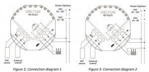
 Follow connection diagrams (Figure 2, 3, 4, 5) and the instructions below:• Power wires: for AC power (85-265VAC) connect Line & Neutral lead wires to L & N terminals labeled “IN”. For DC power (24-48VDC) connect “+” wire to terminal N and “–” wire to terminal L.• Load wires: connect Line & Neutral wires to L & N terminals labeled with “heating element” graphicNote: it is possible to connect Neutral wire from load directly to your neutral line (Figure 3 or 5).Note: HELTUN recommends installing cord terminals (electric wire ferrules) on the ends of wires before connecting them to the HE-HLS01 outputs (various colors terminals are included).Note: Zero-Cross technology is unavailable if the device is DC (24-48VDC) powered. Tighten wires using Phillips screwdriver in slot beneath each wire.
 - If using the HE-HLS01 for radiant floor heating, connect the NTC temperature sensor wire to the terminals labeled “NTC.” A 10 kΩ NTC sensor is included inside the HE-HLS01 packaging, but any NTC sensor can be used.Note: If an NTC sensor other than 10 kΩ is used, you must change the sensor resistance value in Parameter 8.
- If you will be using an external device to select modes for the HE-HLS01 (such as a security system or wall switch),connect wires from the external device’s dry contacts to the two HE-HLS01 terminals labeled “S1” & “Sx”.Two different connection methods for external control are possible:• Connect S1 to Sx through dry contact switch (as in Figures 2 & 3)• Connect S1 to electric network Line through dry contact switch (as in Figures 4 & 5)Note: In case of connecting S1 to electric network Line, it is MANDATORY to connect S1 terminal to the same wire connected to terminal L on the device (labeled as “IN”).
- Switch On the main power at the circuit breaker. The HE-HLS01 will start up with the original default factory settings and the LED indicator will blink red slowly meaning the device is excluded from a Z-Wave network.
 Note: HELTUN recommends installing cord terminals (electric wire ferrules) on the ends of wires before connecting them to the HE-HLS01 outputs (various colors terminals are included).Note: Zero-Cross technology is unavailable if the device is DC (24-48VDC) powered. Tighten wires using Phillips screwdriver in slot beneath each wire.
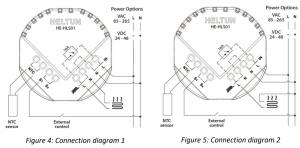
Disassembly
- ENSURE POWER IS SWITCHED OFF at the main circuit breaker AND THE LED INDICATOR IS OFF.
- Disconnect the wires by inserting a small Phillips-head screwdriver into the slot beneath each wire and unscrewing to release.
Factory Reset (RES)
To reset the HE-HLS01 to factory defaults, press and hold the service button for six seconds. If successful, the LED indicator will blink white for two seconds then the device will reboot.The factory reset will change all the Parameters to their original factory default values and will also Exclude the device from any Z-Wave network.Note: Please use this procedure only when the network primary controller is missing or otherwise inoperable.
Common Configurations
1-30 configuration parameters are common for both “Binary Switch” and “Thermostat” device types.All configuration parameters are accessed through COMMAND_CLASS_CONFIGURATION
|
Parameter Number |
Parameter Size |
Parameter Name |
Default Value |
Available Values |
|
1 |
1 byte |
DEVICE TYPE |
0 |
0, 1 |
|
2 |
1 byte |
FREQUENCY REGION |
0 |
0 … 9 |
|
3 |
1 byte |
OUTPUT MODE |
0 |
0, 1 |
|
4 |
1 byte |
TIME CORRECTION |
1 |
0, 1 |
|
5 |
1 byte |
WEEKDAY |
1 |
1, 2, 3, 4, 5, 6, 7 |
|
6 |
1 byte |
HOUR |
0 |
0 … 23 |
|
7 |
1 byte |
MINUTE |
0 |
0 … 59 |
|
8 |
1 byte |
NTC RESISTANCE |
10 |
1 … 100 |
|
9 |
1 byte |
TEMPERATURE SENSOR OFFSET |
0 |
(-100) … 100 for °C,(-17) … 17 for °F |
|
10 |
1 byte |
TEMPERATURE SCALE MODE |
0 |
0, 1 |
|
11 |
1 byte |
TEMPERATURE REPORT INTERVAL |
10 |
1 … 120 |
|
12 |
1 byte |
TEMPERATURE REPORT THRESHOLD |
5 |
0, 1 … 100 for °C,0, 1 … 18 for °F |
|
13 |
1 byte |
METER REPORT INTERVAL |
10 |
1 … 120 |
|
14 |
1 byte |
METER REPORT THRESHOLD |
25 |
0, 1 … 90 |
|
15 |
1 byte |
SYSTEM ERROR NOTIFICATION |
1 |
0, 1 |
|
16 |
2 bytes |
TEMPERATURE RISE NOTIFICATION |
50 for °C,122 for °F |
0 … 120 for °C,32 … 248 for °F |
|
17 |
2 bytes |
OVERHEAT PROTECTION LEVEL |
60 for °C,140 for °F |
0 … 120 for °C,32 … 248 for °F |
|
18 |
1 byte |
OVERCURRENT NOTIFICATION |
1 |
0, 1 |
|
19 |
2 bytes |
OVERLOAD PROTECTION LEVEL |
3500 |
0, 100 …. 4000 |
|
20 |
2 bytes |
OVERVOLTAGE PROTECTION LEVEL |
240 |
0, 120 … 280 |
|
21 |
2 bytes |
VOLTAGE DROP PROTECTION LEVEL |
200 |
0, 80 … 240 |
|
22 |
1 byte |
SPARK PROTECTION |
1 |
0, 1 |
|
23-30 |
4 bytes |
RESERVED BY MANUFACTURER |
Parameter 01 – Device TypeThis parameter is read only and indicates in which mode the device is included. The device can be included either in the Binary Switch mode or in the Thermostat mode. Use inclusion in Binary Switch mode if there is a need to control on/off device and use inclusion in Thermostat mode if there is a need to control heating system. For the appropriate inclusion process see the section Z-Wave Network of this manual.
Parameter 02 – Frequency RegionThe HLS01 has Z-Wave 700 platform chip inside which allows to use the device in different Z-Wave frequencies. If there is a need to use the device in the frequency different from the factory default change the value of this parameter according to the list below.Note: The factory default frequency differs depending on which region the device was intended for sale in. Check the factory default frequency on the device plate or on the packaging.Note: Don’t change this parameter value if there is no a special need.Note: The frequency change will be applied only after removing from Z-Wave network and automatic reboot of the device․Note: The change of this parameter will result in inability to control the device, if the device was included to the controller/gateway which supports only one frequency,Note: Resetting the device to factory default settings will revert back the frequency to the factory default value.Note: In most of countries it is not allowed to use the frequency different from the frequency intended for that country.
Frequency list for different regions:
| 0: EU (868.4 MHz, 869.85 MHz)1: US (908.4 MHz, 916.0 MHz)2: ANZ (919.8 MHz, 921.4 MHz)3: HK (919.8 MHz)4: IN (865.2 MHz) | 5: IL (916.0 MHz)6: RU (869.0 MHz)7: CH (868.4 MHz)8: JP (922.5 MHz, 923.9 MHz, 926.3 MHz)9: KR (920.9 MHz, 921.7 MHz, 923.1 MHz) |
The full list of Z-Wave global regions where Z-Wave works is available at Z Wave Global Regions SiLabs page.
Parameter 03 – Output NO/NC ModeThe device can operate in Normal Open (NO) mode and in Normal Close (NC) mode. If the Parameter value = 0, the device switch operates in NO mode and there is no voltage on output when the device is in OFF state. The output will be powered when device goes to ON state. If the Parameter value = 1, the output will be powered in OFF state and will be no voltage on output when the device is in ON state.The factory default value is 0.
Time Configuration
Parameter 04 – Time Correction by GatewayIf this Parameter value = 1 and the HE-HLS01 is connected to a Z-Wave gateway, the HE-HLS01 time and day will be periodically polled and corrected from the gateway. To switch off auto correction set the Parameter value to 0. The factory default value is 1.
Parameter 05 – Day of the WeekAllows manually adjustment of the day of the week in case the HE-HLS01 is not connected to any Z-Wave gateway or the Parameter 04 (auto-correction) is set to 0. The value of this parameter can be set from 1 to 7: 1 = Monday, 2 = Tuesday, 3 = Wednesday, 4 = Thursday, 5 = Friday, 6 = Saturday, 7 = Sunday. The factory default value is 1.
Parameter 06 – Clock HoursAllows manually adjustment of hours for internal clock in case the HE-HLS01 is not connected to any Z-Wave gateway or the Parameter 04 (auto-correction) is set to 0. The value of this parameter can be set from 0 to 23.The factory default value is 0.
Parameter 07 – Clock MinutesAllows manually adjustment of minutes for internal clock in case the HE HLS01 is not connected to any Z-Wave gateway or the Parameter 04 (auto-correction) is set to 0. The value of this parameter can be set from 0 to 59. The factory default value is 0.
Sensors Configuration
Parameter 08 – External NTC Temperature Sensor ResistanceIf the external NTC temperature sensor is used it is necessary to select the correct resistance value in Ohms (Ω) of the sensor. The selection range is 1 to 100 kiloOhms (kΩ). One 10kΩ NTC temperature sensor is included in the HE-HLS01 package with a 3-meter connection wire.The factory default value is 10.
Parameter 09 – Temperature Sensor CalibrationThis Parameter defines the offset value for external NTC temperature sensor. If the temperature sensor is not calibrated properly, manual calibration can be made by adjusting the values up to ±10.0°C or ±18°F. This value will be added or subtracted from the temperature sensor reading.The factory default value is 0.
Parameter 10 – Temperature Scale ModeThis parameter determines in which unit of measurement (degrees Celsius or Fahrenheit) the device will report the temperature, and also determines the scale that will be interpreted by the configuration parameters. Set the value 0 for Celsius and the value 1 for Fahrenheit.Factory default value is 0 (degrees Celsius).Note: This configuration parameter has impact on configuration parameters 9,12,16,17 and 32, 42-69 in thermostat mode. If scale is set to degrees Fahrenheit, configuration values at mentioned parameters will be automatically converted from Celsius to Fahrenheit and any change in the values will be interpreted as Fahrenheits.
Parameter 11 – Temperature Sensor Consecutive Report IntervalThis Parameter defines the interval between consecutive reports of temperature sensor reading to the gateway. Thevalue can be adjusted from 1 min to 120 min.The factory default value is 10 min.Note: If the sensor readings change, the device will send the report to the gateway regardless of this parameter value.In order not to increase traffic on your network, it is not recommended to reduce the value of this parameter. We recommend reducing the value of this parameter only in case of poor connection, when reports from the device does not always reach the gateway.
Parameter 12 – Temperature Sensor Report ThresholdThis parameter determines the change in temperature level resulting in temperature sensors report being sent to the gateway. In Celsius scale mode the value of this parameter should be x10, e.g. for 0.4°C use value 4. From 1 (0.1°C) to 100 (10°C) can be selected in Celsius scale mode and from 1 to 18 can be selected in Fahrenheit scale mode. Use the value 0 if there is a need to stop sending the reports.The factory default value is 5 (0.5°) in °C scale and 1 in °F scale.
Parameter 13 – Energy Consumption Meter Consecutive Report IntervalWhen the device is connected to the Z-Wave gateway (controller), it periodically sends to the gateway reports from its external temperature sensor and energy consumption meter even if there are not changes in the values. This Parameter defines the interval between consecutive reports of real time and cumulative energy consumption data to the gateway. The value can be adjusted from 1 min to 120 min.The factory default value is 10 min.Note: If the sensor readings change, the device will send the report to the gateway regardless of this parameter value.In order not to increase traffic on your network, it is not recommended to reduce the value of this parameter. We recommend reducing the value of this parameter only in case of poor connection, when reports from the device does not always reach the gateway.Note: Energy consumption meter function is available only if the device is AC powered.
Parameter 14 – Energy Consumption Meter Report ThresholdThis parameter determines how much the cumulative or real time energy consumption data need to increase/reduce to be reported to the gateway. The value of this parameter is in % and from 1 to 90 can be selected. Use the value 0 if there is a need to stop sending the reports.The factory default value is 25.Note: Energy consumption meter function is available only if the device is AC powered.
Protections and Notifications
Parameter 15 – Device Failure NotificationsIf the HLS01 does not work properly it sends “System Failure” notification to the gateway with the error code. Set the value 1 to enable “System Failure” notification or the value 0 to disable.The factory default value is 1 (the notification is enabled).Errors code list (sent with the notification):0 – No Error (no issue is detected)1 – Relay Off Error (when unable to switch Off the relay output).2 – Relay On Error (when unable to switch On the relay output).3 – Relay On & Off Error (when unable to switch On and Off the relay output).4 – NTC Error (when no NTC sensor is detected or when it is damaged).5 – NTC and Relay Off Error (when no NTC sensor is detected or when it is damaged and unable to switch Off the relay output).6 – NTC and Relay On Error (when no NTC sensor is detected or when it is damaged and unable to switch On the relay output).7 – NTC and Relay On & Off Error (when no NTC sensor is detected or when it is damaged and unable to switch On and Off the relay output).
Parameter 16 – Temperature Rise NotificationUse this parameter if you want to know about temperature rise before it reaches the critical value, defined in the “Overheat Protection” parameter. The device will send “Rapid Temperature Rise” notification to the gateway if the temperature sensor reading reaches the value defined in this parameter. The value can be set from 1 to 120 in °C scale mode or from 32 to 248 in °F scale mode. To disable the notification, set the value of this parameter to 0.The factory default value is 50 in °C scale and 122 in °F scale.Note: We recommend setting the value of this Parameter lower than value of Parameter 17 (Overheat Protection).
Parameter 17 – Overheat Protection & NotificationYou can define the maximum limit of temperature, reaching which the device will automatically switch Off the load and send “Overheat Detected” notification to the gateway. The value of this parameter can be set from 1 to 120 in °C scale mode or from 32 to 248 in °F scale mode. Use the value 0 if there is a need to disable this function.The factory default value is 60 in °C scale and 140 in °F scale.
Parameter 18 – Over-Current Protection & NotificationThe maximum load for the device is 16A. If the connected load current exceeds 16A the device will automatically switch Off the output and send the “Over-Current Detected” notification to the gateway. To disable sending the notification, set the value of this Parameter to 0.The factory default value is 1 (the notification is enabled).Note: Even if you turn off the notification, the device will switch Off the load when the current reaches 16A.Note: The protection works only if the device is AC powered.
Parameter 19 – Over-Load Protection & NotificationYou can define the maximum power in Watt for connected load. The device will automatically switch off the output and send “Over-Load Detected” notification to the gateway if power consumed by the connected load exceeds this limit. The value of this parameter can be set from 100 to 4000 in watts. Use the value 0 if there is a need to disable this function.The factory default value is 3500W.Note: The protection works only if the device is AC powered.
Parameter 20 – Over-Voltage Protection & NotificationThe device constantly monitors the voltage of your electricity network. You can define the maximum voltage of network exceeding which the device will automatically switch off the output and send “Over-Voltage Detected” notification to the gateway. The value of this parameter can be set from 120 to 280 in volts. Use the value 0 if there is a need to disable this function.The factory default value is 240V.Note: The protection works only if the device is AC powered.
Parameter 21 – Voltage Drop Protection & NotificationYou can define the minimum voltage of your electricity network. If the voltage of the network drops determined level the device will automatically switch off the output and send “Voltage Drop Detected” notification to the gateway. The value of this parameter can be set from 80 to 240 in volts. Use the value 0 if there is a need to disable this function.The factory default value is 200V.Note: The protection works only if the device is AC powered.
Parameter 22 – Sparks Protection & NotificationIf connected load fails it can create sparks that may cause a fire. The device constantly monitors the power consumption of connected load and can detect even a small surge in consumption and automatically switch off the output and send “Surge Detected” notification to the gateway. Set the value 1 to enable this function or the value 0 to disable.The factory default value is 1 (the protection is enabled).Note: The protection works only if the device is AC powered.
Parameters 23 – 30 – Reserved by ManufacturerWe reserved these parameters for future updates and new functionality. Changing of these parameters will not have any effect to the device logic.
Device type “Binary Switch”
These parameters will take affect only in case if the device is included in the Binary Switch mode. For more information about the different inclusion modes see the section Z-Wave Network.
|
Number |
Size |
Name | Default Value |
Available Values |
|
31 |
1 byte |
LOAD ON NOTIFICATION |
0 |
0, 1 |
|
32 |
1 byte |
LOAD OFF NOTIFICATION |
0 |
0, 1 |
|
33 |
2 byte |
TIME LIMITITED LOAD |
0 |
0, 100 … 3500 |
|
34 |
2 byte |
HIGH LOAD ON TIME LIMIT |
0 |
0 …. 1440 |
|
35 |
1 byte |
LOAD AUTO ON/OFF |
0 |
0, 1 |
|
36 |
1 byte |
AUTO OFF TIMEOUT |
5 |
0 … 120 |
|
37 |
1 byte |
AUTO ON RECONNECT TIMEOUT |
0 |
0 … 120 |
|
38 |
1 byte |
S1 INPUT HOLD CONTROL MODE |
2 |
0, 1, 2, 3 |
|
39 |
1 byte |
S1 INPUT CLICK CONTROL MODE |
1 |
0, 1, 2, 3, 4, 5 |
|
40 |
2 bytes |
RELAY TIMER DURATION |
0 |
0 … 43200 |
|
41 |
4 bytes |
RELAY CONTROL SCENARIO 1 |
0 |
0, 1000000 … 1912359 |
|
42 |
4 bytes |
RELAY CONTROL SCENARIO 2 | ||
|
43 |
4 bytes |
RELAY CONTROL SCENARIO 3 | ||
|
44 |
4 bytes |
RELAY CONTROL SCENARIO 4 | ||
|
45 |
4 bytes |
RELAY CONTROL SCENARIO 5 | ||
|
46 |
4 bytes |
RELAY CONTROL SCENARIO 6 | ||
|
47 |
4 bytes |
RELAY CONTROL SCENARIO 7 | ||
|
48 |
4 bytes |
RELAY CONTROL SCENARIO 8 | ||
|
49 |
4 bytes |
RELAY CONTROL SCENARIO 9 | ||
|
50 |
4 bytes |
RELAY CONTROL SCENARIO 10 | ||
|
51 … 60 |
4 bytes |
RESERVED BY MANUFACTURER |
Protections and Notifications
Parameter 31 – Load Switched On NotificationIf this function is enabled the device will send “AC Mains Re-Connected” notification to the gateway each time when the relay output state changes to On. To enable this notification, set the value of this parameter to 1.The factory default value is 0 (notification is disabled).Note: This function can be useful for informing in case of automatic control of the load by schedule or scenario.
Parameter 32 – Load Switched Off NotificationIf this function is enabled the device will send “AC Mains Disconnected” notification to the gateway each time when the relay output state changes to Off. To disable this notification, set the value of this parameter to 0.The factory default value is 0 (notification is enabled).Note: This function can be useful for informing when the device automatically switches the output Off because of emergency case or in case of automatic control of the load by schedule or scenario.
Parameter 33 – High Load Timeout Protection: Power ThresholdIf the HLS01 is used to control an electric socket, you can configure the device so that it automatically switch Off the socket if the potentially dangerous high load is connected longer than allowable time (time to be set in the Parameter34), for example, if you left the iron switched On for too long. Set in this parameter the threshold value in watts, reaching which the connected load will be considered high. The value of this parameter can be set from 100 to 3500 in watts.Use the value 0 if there is a need to disable this function.The factory default value is 0 (the function is disabled).Note: If the connected load power is less than value of this parameter, the protection will not be activated.Note: If the Parameter 34 (time threshold) value is set to 0, the protection will not be activated.Note: The time counter is reset every time when the load consumption drops to zero.Note: We recommend activating the Load Switched Off notification (the Parameter 32) to be informed when the device automatically switch Off the socket.Note: The protection works only if the device is AC powered.
Parameter 34 – High Load Timeout Protection: Time ThresholdIf High Load Timeout Protection is activated (the Parameter 33 is set) use this parameter to set the threshold value in minutes. If the load is connected longer than this value, the device will automatically switch Off the socket. The value of this parameter is in minutes and can be set from 1 to 1440. Use the value 0 if there is a need to disable this function.The factory default value is 0 (the function is disabled).Note: If the value of this parameter is set 0, the protection will not be activated.Note: If the connected load power is less than value of the Parameter 33, the protection will not be activated.Note: The time counter is reset every time when the load consumption drops to zero. If the connected load may change its consumption, make sure that the time threshold will be reached before the load consumption drops.Note: We recommend activating the Load Switched Off notification (the Parameter 32) to be informed when the device automatically switch Off the socket.Note: The protection works only if the device is AC powered.
Auto On/Off function
Parameter 35 – Auto On/OffIf this function is enabled the device will switch Off the relay output when there is no consumption and switch On theoutput again when the load is reconnected. It is possible to set the delay for Auto Off function (in the Parameter 36) andfor Auto On function (in the Parameter 37). To enable Auto On/Off function, set this Parameter value to 1 and use the value 0 if there is a need to disable the function.The factory default value is 0 (the function is disabled).Note: If the output is manually switched Off (from Gateway or External Input toggle) Auto ON function will be blocked until the output switches back to ON manually or the load disconnected.Note: The function works only if the device is AC powered.
Parameter 36 – Auto Off TimeoutIf Auto On/Off function (the Parameter 35) is enabled, it is possible to delay the Auto Off function. The output will be switched Off when there is no consumption for the interval defined in this parameter in minutes. The value of this parameter can be set from 1 to 120 min. Set the parameter value to 0 if there is a need to switch Off the output immediately when consumption drops to 0W.The factory default value is 5 min.Note: The function works only if the device is AC powered.
Parameter 37 – Auto On Reconnect TimeoutIf Auto On/Off function (the Parameter 35) is enabled, it is possible to delay the Auto On function. When the load is reconnected the relay output will be switched On after the time defined in this parameter in minutes. The value of this parameter can be set from 1 to 120 min. Set the parameter value to 0 if there is a need to switch On the output immediately when the load is reconnected.The factory default value is 0 min.Note: The function works only if the device is AC powered.
External Input Configuration
The HE-HLS01 can be connected to the dry output contacts of an external device (i.e. security system or wall switch) to control the Switch output state depending on the state of the external device.Two different connection diagrams are possible for external input:
- Connect S1 to Sx through dry contact switch
- Connect S1 to electric network Line through dry contact switch
Note: In case of connecting S1 to electric network Line, it is MANDATORY to connect S1 terminal to the same wire connected to terminal L on the device (labeled as “IN”).
Parameter 38 – External Input: Hold Control Mode0 – Hold function is disabled1 – Operate like click (the Parameter 39)2 – Momentary Switch: When the button on switch connected to external input is held, (key closed) the relay output state is ON, as soon as the button is released (key opened) the relay output state changes to OFF.3 – Reversed Momentary Switch: When the button on switch connected to external input is held, the relay output state is OFF, as soon as the button is released the relay output state changes to ON.The factory default value is 2.
Parameter 39 – External Input: Click Control Mode0 – Click function disabled1 – Toggle switch: relay inverts state (ON to OFF, OFF to ON).2 – Relay switches to ON state only3 – Relay switches to OFF state only4 – Timer: On>Off Mode: Relay output switches to ON state (contacts are closed) then after a specified time switches back to OFF state (contacts are open). The time is specified in the Parameter 40.5 – Timer: OFF>ON Mode: Relay output switches to OFF state (contacts are open) then after a specified time switches back to ON state (contacts are closed). The time is specified in Parameter 40.The factory default value is 1.
Parameter 40 – Relay Timer Mode DurationThese parameters specify the duration in seconds for the Timer mode (values 4 or 5 in the Parameter 39). Press the button on the switch connected to external input and the relay output goes to ON/OFF for the specified time thenchanges back to OFF/ON. The time value can be configured from 0 sec to 43200 sec (12 hours).The factory default value is 0.Note: If the parameter value is set to “0” the relay output will operate as a short contact (duration is about 0.5 sec).
Scenarios
Parameters 41-50 – Relay Control by ScenarioIn these parameters, the relay state changes depending on day and time. For these configurations, parameter values are encoded as 7-digit numbers (ABCDEFG).A: State. 0 = Disabled, 1 = EnabledB: Day of week0 = every day1-7 = corresponding day (1 is Monday, 7 is Sunday)8 = every weekday (Monday – Friday)9 = every weekend (Saturday and Sunday)C: Change state to0 = Switch OFF1 = Switch ONDEFG: TimeDE represents Hour (from 0 to 23),FG represents Minutes (from 0 to 59).
All other numbers are reserved and will not affect the operation. To disable this option simply set this parameter to 0.The factory default value is 0.
Example: Parameter value 1210350 means A=1 (the scenario is enabled), B=2 (Tuesday), C=1 (switch the relay On), DEFG=0350 (time 03:50). In this case each Tuesday at 03:50 the relay output will be switched On. To disable the scenario, change the first digit to 0. In this example it will be 0210350.
Note: The relays still can be controlled manually using External Inputs or via controller/gateway.Note: The logic will implement the operation when the time crosses the value in the Parameter. Meaning, that if the logic switches On the relay and you manually switch it Off, the relay will switch On next time when the value crosses the set parameter.Note: 10 different scenarios can be implemented (one scenario in each parameter 50-59), but make sure you don’t use the same time (DEFG) in different scenarios.
Parameters 51 – 60 – Reserved by ManufacturerWe reserved these parameters for future updates and new functionality. Changing of these parameters will not have any effect to the device logic.
Device type “Thermostat”
Operation Modes
When the HE-HLS01 is included as Thermostat it has 6 Operating Modes:
- Heat – Comfort Mode
- Auto Change Over – Time Mode (schedule different Set Point per time and day)
- Dry – Floor Fast Drying Mode
- Energy saving – Power Efficient Mode
- Away – Vacation Mode
- Off – Thermostat IDLE Mode
Each operating mode has individual temperature Set Points. The HE-HLS01 will operate automatically depending on the current Set Point. You may control Set Points through your Z-Wave gateway software.Note: The minimum Set Point is 1.0°C (or 34°F) and the maximum Set Point is 110.0°C (or 230°F).
Heat Mode
This mode is recommended for normal comfort. The factory default set point is 25.0°C (77°F).
Auto Changeover Mode – Temperature Schedule Mode
The Temperature Schedule Auto Mode can adjust home temperatures automatically to align with your personal habits, saving energy while you are away, and maintaining a comfortable temperature while you are active at home.
The HE-HLS01 can have different Schedules for Morning, Daytime, Evening and Night. For example, the “Morning” Schedule could be set to 25.0°C (77°F) starting at 7:00. The “Day” Schedule could then be set to 11.0°C (or 52°F) at 9:00 when everyone has gone to work or school, and so on. Here are recommended Scheduled Set Points for heating during the work week – you may wish to change these on weekends depending on your family’s schedule (see example below):
|
Schedule Mode |
Set Time |
Set Point Temperature |
|
Morning |
6:00 (6:00am) |
24°C (75°F) |
|
Day |
9:00 (9:00am) |
20°C (68°F) |
|
Evening |
18:00 (6:00pm) |
23°C (73°F) |
|
Night |
23:00 (11:00pm) |
18°C (64°F) |
Note: All four Schedules (Morning, Day, Evening, & Night) are the same for all seven days of the week.Note: Auto mode will only work properly if the correct current time and date have been set. The time can be automatically corrected from your Z-Wave gateway if the Parameter 04 value is set to 1. Or it can be set manually in Parameters 05, 06, and 07.Note: In Auto mode, the temperature Set Point will be automatically changed depending on the Schedule. At any time, the Set Point can be adjusted but it will be effective only until the next Schedule.
DRY – Fast Floor Drying Mode
This mode is recommended for use if a high floor temperature is required for a limited period of time. For example, after washing the floor. By choosing DRY Mode, the HE-HLS01 will increase the temperature to the selected Set Point for the time specified in the “Dry Time” parameter (Parameter 36). A time range from 1 to 720 minutes (12 hours) can be set. As the Dry Time passes, the HE-HLS01 will automatically change to the Mode set in Parameter 37.Note: Factory defaults for Dry Time are: 30 minutes at 30.0°C (86°F).
Energy Saving Mode
This Mode can be used if lower temperature and energy consumption is desired. It can also be used at night or when away from all or part of the property for a length of time. The factory default Set Point is 20.0°C (68°F).
Away Mode
Use Vacation Mode when you are planning to be away from home for some period. The factory default temperature Set Point is 15.0°C (59°F).Note: The minimum set point for each mode is 1.0°C (34°F) and the maximum set point is 110.0°C (230°F).
Parameters
These parameters will take affect only in case if the device is included in the Thermostat mode. For more information about the different inclusion process see the section Z-Wave Network.
|
Number |
Size | Name | Default Value |
Available Values |
|
31 |
1 byte |
LOAD ERROR NOTIFICATION |
0 |
0, 1 |
|
32 |
1 byte |
TEMPERATURE REGULATION HYSTERESYS |
50 for °C, 1 for °F |
2 … 100 for °C,1 … 18 for °F |
|
33 |
1 byte |
BASIC SET MODE |
1 |
1, 2, 3, 4, 5 |
|
34 |
1 byte |
S1 INPUT MODE |
0 |
0, 1, 2, 3 |
|
35 |
1 byte |
S1 INPUT ACTION |
1 |
1, 2, 3, 4, 5 |
|
36 |
2 byte |
DRY TIME |
30 |
1 … 720 |
|
37 |
1 byte |
DRY MODE SWITCH |
1 |
1, 2, 4, 5, 6 |
|
38 |
2 bytes |
MORNING START TIME |
0600 |
0000 … 2359 |
|
39 |
2 bytes |
DAY START TIME |
0900 |
|
|
40 |
2 bytes |
EVENING START TIME |
1800 |
|
|
41 |
2 bytes |
NIGHT START TIME |
2300 |
|
|
42 |
2 bytes |
MONDAY MORNING TEMP |
240 for °C, 75 for °F |
10 … 1100 for °C, 34 … 230 for °F |
|
43 |
2 bytes |
MONDAY DAYTIME TEMP |
200 for °C, 68 for °F |
|
|
44 |
2 bytes |
MONDAY EVENING TEMP |
230 for °C, 73 for °F |
|
|
45 |
2 bytes |
MONDAY NIGHT TEMP |
180 for °C, 64 for °F |
|
|
46 … 49 |
2 bytes |
TUESDAY MORNING TEMPTUESDAY DAYTIME TEMPTUESDAY EVENING TEMPTUESDAY NIGHT TEMP |
Same as for Monday (42 – 45) |
|
|
50…53 |
2 bytes |
WEDNESDAY MORNING TEMPWEDNESDAY DAYTIME TEMPWEDNESDAY EVENING TEMPWEDNESDAY NIGHT TEMP |
Same as for Monday (42 – 45) |
|
|
54…57 |
2 bytes |
THURSDAY MORNING TEMPTHURSDAY DAYTIME TEMPTHURSDAY EVENING TEMPTHURSDAY NIGHT TEMP |
Same as for Monday (42 – 45) |
|
|
58…61 |
2 bytes |
FRIDAY MORNING TEMPFRIDAY DAYTIME TEMPFRIDAY EVENING TEMPFRIDAY NIGHT TEMP |
Same as for Monday (42 – 45) |
|
|
62…65 |
2 bytes |
SATURDAY MORNING TEMPSATURDAY DAYTIME TEMPSATURDAY EVENING TEMPSATURDAY NIGHT TEMP |
Same as for Monday (42 – 45) |
|
|
66…69 |
2 bytes |
SUNDAY MORNING TEMPSUNDAY DAYTIME TEMPSUNDAY EVENING TEMPSUNDAY NIGHT TEMP |
Same as for Monday (42 – 45) |
|
|
70…80 |
4 bytes |
RESERVED BY MANUFACTURER |
Parameter 31 – Load Error NotificationThe device can send the “Load Error” notification to the gateway when the relay is On but there is no power consumption (meaning possible problems with the heating system). Set the value 1 to enable “Load Error” notification or the value 0 to disable.The factory default value is 1 (the notification is enabled).Note: The function works only if the device is AC powered.
Parameter 32 – Temperature HysteresisThis Parameter defines the hysteresis value for temperature control. The HE HLS01 will stabilize the temperature with selected hysteresis. For example, if the SET POINT is set for 25°C and HYSTERESIS is set for 0.5°C the HE-HLS01 will change the state to IDLE when the temperature reaches 25.0°C, but it will change the state to HEATING if the temperature drops lower than 24.5°C. The hysteresis can be changed from 0.2°C to 10.0°C range in Celsius mode, and from 1°F to 18.0°F in Fahrenheit mode. The factory default value is 0.5°C and 1°F.
Parameter 33 – Basic Set ActionThis Parameter defines which Operating Mode the HE-HLS01 reverts to if the Basic Set command is received. If the Basic Set command value is 0 (OFF state) the HE-HLS01 will go to Manual mode and switch Off the heating element (IDLE mode). If the Basic Set command is value is 0xFF (ON state) the HE HLS01 will change the Mode to the corresponding Parameter value as follows.1: Heat Mode2: Auto Mode3: Dry Mode4: Energy Saving Mode5: Away ModeThe factory default value is 1
External Input Configuration
The HE-HLS01 can be connected to the dry output contacts of an external device (i.e. security system or window sensor) to control the Thermostat operating modes depending on the state of the external device.Two different connection diagrams are possible for external input:
- Connect S1 to Sx through dry contact switch
- Connect S1 to electric network Line through dry contact switch
Note: In case of connecting S1 to electric network Line, it is MANDATORY to connect S1 terminal to the same wire connected to terminal L on the device (labeled as “IN”).
Parameter 34 – External Input Mode0 – the input state changes will be ignored by the Thermostat logic.1 – the external input will operate in “Toggle Switch” mode: if the external input is shorted (with Sx or Line) theThermostat switches to the operating mode selected in the Parameter 35 and switches to OFF mode when the external input is open.2 – the external input will operate in “Toggle Switch Reverse” mode: if the external input is shorted the Thermostat switches to OFF mode and switches to the operating mode selected in the Parameter 35 when the input is open.3 – the external input will operate in “Push Button (Momentary Switch)” mode: each press of button (shorten of input) will consistently change the mode to the operating mode selected in the Parameter 35 .The factory default value is 0.
Parameter 35 – External Input ActionThis Parameter allows selection of which Operating Mode the HE-HLS01 should revert to when the external input is shorted. 1 = Heat, 2 = Auto, 3 = Dry, 4 = Energy Saving, 5 = Away.The factory default value is 1.
Parameter 36 – Dry Mode TimeoutBy choosing Dry Mode, the device will increase the temperature to the selected Set Point and keep it for the time specified in this parameter. A time range of 1 to 720 minutes (12 hours) can be set. As the Dry Time passes, theThermostat will automatically change to the Mode set in the Parameter 37.The factory default value is 30 minutes.
Parameter 37 – Mode to Switch After Dry Mode Operation CompleteThis Parameter indicates the mode that will be set after Dry Time: 1 = Heat, 2 = Auto, 4 = Energy Saving, 5 = Away, 6 = Off.The factory default value is 1.Note: The value 3 (Dry mode) will be ignored for this parameter.
Parameters 38-41 – Schedule TimeUse these parameters to manual set the Morning, Day, Evening and Night times for the Temperature Schedule.The value of these parameters has format HHMM, e.g. for 08:00 use value 0800 (time without a colon). From 00:00 to23:59 can be selected.The factory default value for Morning (Parameter 38) is 0600.The factory default value for Day (Parameter 39) is 0900.The factory default value for Evening (Parameter 40) is 1800.The factory default value for Night (Parameter 41) is 2300.
Parameters 42-69 – Schedule TemperatureUse these parameters to manual set the temperature for each day Schedule.In Celsius scale the value of this parameter should be x10, e.g. for 22.5°C use value 225. From 1°C (value 10) to 110°C (value 1100) in Celsius scale and from 34°F (value 34) to 230°F (value 230) in Fahrenheit scale can be selected.For the default and available values check the parameters list.
Parameters 70 – 80 – Reserved by ManufacturerWe reserved these parameters for future updates and new functionality. Changing of these parameters will not have any effect to the device logic.
Power and Energy Consumption
HE-HLS01 monitors active power energy consumption and Voltage using advanced micro-controller technology which assures maximum accuracy (±1% for loads greater than 1000W). Real time consumption, cumulative consumption, and network voltage are periodically reported to the Z-Wave controller.Resetting cumulative consumption memory:The Heating Thermostat allows to erase stored consumption data through z wave network.
- Make sure the device is powered.
- Include the device to Z-Wave Gateway /Network
- Reset memory consumption data using Reset Command in COMMAND_CLASS_METER (see the controller’s manual).
Note: Turning the device main power off/on will not erase the consumption data as it is stored in nonvolatile memory.
Z-Wave Network
The HE-HLS01 may be operated in any Z-Wave network with other Z-Wave certified devices from other manufacturers. The HELTUN HE-HLS01 will act as a ‘repeater’ for other devices regardless of manufacturer or brand to increase the reliability of the overall network.
Including HE-HLS01 to an Existing Z-Wave Network
To add the HE-HLS01 to an existing Z-Wave network (i.e. “inclusion”), do the following:
- Ensure the HE-HLS01 is Powered On and the LED indicator blinks red slowly (i.e. it is excluded).
- Start the Inclusion Mode from the gateway/controller.
- To start the inclusion process on the HE-HLS01:a) if you want to use the device as a “Binary Switch”, double-press the service button on the device (with no more than a one-second interval between presses).b) if you want to use the device as a “Thermostat”, press four times the service button on the device (with no more than a one-second interval between presses).
- The LED indicator will blink green quickly.
- If the inclusion has been successful, the LED indicator will turn green for three seconds then continue slowly blinking green continuously while the HE-HLS01 is Powered On.
- If the inclusion was not successful, the LED indicator will turn red for three seconds then continue slowly blinking red continuously while the HE-HLS01 is Powered On. In that case repeat the inclusion process (2-5) above.
Removing HE-HLS01 from Z-Wave network
To remove the HE-HLS01 from a Z-Wave network (i.e. “Exclusion”), do the following:
- Ensure the HE-HLS01 is Powered On and the LED indicator blinks green slowly (i.e. it is included in a Z-Wave network).
- Start the Exclusion Mode from the gateway/controller.
- To start the exclusion process on the HE-HLS01, double-press the service button on the device (with no more than a one-second interval between presses).
- The LED indicator will blink red quickly.
- If the exclusion has been successful, LED indicator will turn red for three seconds then continue slowly blinking red continuously while the HE-HLS01 is Powered On.
- If the exclusion was not successful, the LED indicator will turn green for three seconds then continue slowly blinking green continuously while the HE-HLS01 is Powered On. In that case repeat the exclusion process (2-5) above.
Note: If the HE-HLS01 has previously been part of a Z-Wave network and not Excluded since, Inclusion is not possible without first performing an Exclusion or Factory Reset procedure.
Security
S0, S2 unauthorized, and S2 authorized Inclusion Modes are supported. If you use the S2 authorized Inclusion Mode the security key should be used during the inclusion process. The Security Key is printed on a card located with this quick start guide and also on the device.Note: Be sure to save this key. Without the key, it is impossible to perform an Inclusion in S2 authorized mode.
SmartStart
SmartStart-enabled products can be added to a Z-Wave network by scanning the Z-Wave QR Code shown on the product with gateways/controllers that provide for SmartStart inclusion. In this case, no further action will be required and the SmartStart product will be added automatically within ten minutes of being turned on in the vicinity of a network.
To add the HE-HLS01 to the Z-Wave network using SmartStart:
- Input the High Load Switch DSK to the controller’s Node Provisioning List (or scan the QR code)
- Power on the device.
- Wait for the adding process to complete.
- Successful adding will be confirmed by a message on the Z-Wave controller and the LED indicator on HE-HLS01 will turn green for three seconds then continue to slowly blink green continuously while the device is Powered On.
Note: The device security code (DSK) and SmartStart QR code are printed on the rear and front of the HE-HLS01 plus on the additional Security Card included in the packaging (see Figure 6).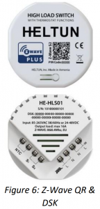 Note: During SmartStart inclusion the device will be included to the gateway as a binary switch. If you want to use the device as a thermostat, use manual inclusion process.
Associations
Association enables the HE-HLS01 to control other Z-Wave devices over the network. An Association Group may include up to ten other devices from different brands and/or manufacturers. The HE-HLS01 has four association groups:Group 1 – “Lifeline”: reports state of the device and used to communicate with the Z-Wave gateway. Max supported nodes: 1Note: It is not recommended to modify this group.Group 2 – “Relay Basic Set”: is assigned to the HE-HLS01 relay state. It sends a Basic Set command with value 255 (On) when relay goes to On state and sends 0 (Off) when relay goes to Off state. Max supported nodes: 1Group 3 – “S1 Basic Set”: is assigned to the HE-HLS01 external input state. It sends a Basic Set command with value 255 (On) when external input is shorted and sends 0 (Off) when input is open. Max supported nodes: 1Group 4 – “Temperature Sensor”: is assigned to the HE-HLS01 external temperature sensor and sends the sensor value when it changes. Max supported nodes: 1
The device also can receive Basic Set command via associations. In the “Binary Switch” mode the device will change the relay state according to the value in Basic Set command. In the “Thermostat” mode the device will change the operating more according to the Parameter 33 value.
Z-Wave Plus V2 Specifications
Thermostat Generic Device Class: GENERIC_TYPE_THERMOSTATThermostat Specific Device Class: SPECIFIC_TYPE_THERMOSTAT_GENERAL_V2Binary Switch Generic Device Class: GENERIC_TYPE_SWITCH_BINARYBinary Switch Specific Device Class: SPECIFIC_TYPE_NOT_USED
Supported Command Classes
Supported Command Classes
|
Command Class |
Version | Required Security Class | Binary Switch |
Thermostat |
| Z-Wave Plus Info |
V2 |
none |
∨ |
∨ |
| Association |
V2 |
highest granted (S2 Authenticated, S2 Unauthenticated or S0) |
∨ |
∨ |
| Association Group Info |
V3 |
highest granted (S2 Authenticated, S2 Unauthenticated or S0) |
∨ |
∨ |
| Multi Channel Association |
V3 |
highest granted (S2 Authenticated, S2 Unauthenticated or S0) |
∨ |
∨ |
| Thermostat Operating State |
V1 |
highest granted (S2 Authenticated, S2 Unauthenticated or S0) |
Χ |
∨ |
| Thermostat Mode |
V3 |
highest granted (S2 Authenticated, S2 Unauthenticated or S0) |
Χ |
∨ |
| Thermostat Setpoint |
V3 |
highest granted (S2 Authenticated, S2 Unauthenticated or S0) |
Χ |
∨ |
| Switch Binary |
V2 |
highest granted (S2 Authenticated, S2 Unauthenticated or S0) |
∨ |
Χ |
| Sensor Multilevel |
V11 |
highest granted (S2 Authenticated, S2 Unauthenticated or S0) |
∨ |
∨ |
| Meter |
V5 |
highest granted (S2 Authenticated, S2 Unauthenticated or S0) |
∨ |
∨ |
| Clock |
V1 |
highest granted (S2 Authenticated, S2 Unauthenticated or S0) |
∨ |
∨ |
| Transport Service |
V2 |
none |
∨ |
∨ |
| Security 0 |
V1 |
none |
∨ |
∨ |
| Security 2 |
V1 |
none |
∨ |
∨ |
| Version |
V3 |
highest granted (S2 Authenticated, S2 Unauthenticated or S0) |
∨ |
∨ |
| Manufacturer Specific |
V2 |
highest granted (S2 Authenticated, S2 Unauthenticated or S0) |
∨ |
∨ |
| Device Reset Locally |
V1 |
highest granted (S2 Authenticated, S2 Unauthenticated or S0) |
∨ |
∨ |
| Powerlevel |
V1 |
highest granted (S2 Authenticated, S2 Unauthenticated or S0) |
∨ |
∨ |
| Supervision |
V1 |
none |
∨ |
∨ |
| Indicator |
V3 |
highest granted (S2 Authenticated, S2 Unauthenticated or S0) |
∨ |
∨ |
| Configuration |
V4 |
highest granted (S2 Authenticated, S2 Unauthenticated or S0) |
∨ |
∨ |
| Application Status |
V1 |
none |
∨ |
∨ |
| Firmware Update Meta Data |
V5 |
highest granted (S2 Authenticated, S2 Unauthenticated or S0) |
∨ |
∨ |
| Basic |
V2 |
highest granted (S2 Authenticated, S2 Unauthenticated or S0) |
∨ |
∨ |
| Notification |
V8 |
highest granted (S2 Authenticated, S2 Unauthenticated or S0) |
∨ |
∨ |
Meter Command Class
|
Meter Type |
Scale | Rate Type | Precision |
Size |
|
Electric [0x01] |
Electric_kWh [0x00] |
Import [0x01] |
2 |
4 |
|
Electric [0x01] |
Electric_W [0x02] |
Import [0x01] |
0 |
2 |
|
Electric [0x01] |
Electric_V [0x04] |
Import [0x01] |
0 |
2 |
Notification Types
|
Notification Type |
Event/State |
Binary Switch |
Thermostat |
|
Heat Alarm |
Overheat detected |
∨ |
∨ |
| Rapid temperature rise |
∨ |
∨ |
|
|
System |
System hardware failure (manufacturer proprietary failure code provided) |
∨ |
∨ |
|
Power Management |
AC mains disconnected |
∨ |
Χ |
| AC mains re-connected |
∨ |
Χ |
|
| Over-current detected |
∨ |
∨ |
|
| Over-voltage detected |
∨ |
∨ |
|
| Over-load detected |
∨ |
∨ |
|
| Surge detected |
∨ |
∨ |
|
| Voltage drop/drift |
∨ |
∨ |
|
| Load error |
Χ |
∨ |
LIMITED WARRANTY
HELTUN warrants this product to be free from defects in workmanship or materials, under normal use and service, for a period of one (1) year from the date of purchase by the consumer (“Warranty Period”). HELTUN will extend this Warranty Period to three (3) years from the date of consumer purchase for any consumer who registers their warranty with HELTUN at this website page:bonus.heltun.com. This Limited Warranty applies only to the first end-user of the product and is not transferable.
If during the Warranty Period the product is determined to be defective or malfunctions due to workmanship or materials, HELTUN, at HELTUN’s option, shall either repair or replace the defective product. If the product is defective, (i) return it with dated proof of purchase to the place it was purchased; or (ii) contact HELTUN Customer Care by email at HELTUN Customer Care will make the determination whether the product should be returned or whether a replacement product will be sent to you.
EXCEPT AS MAY BE OTHERWISE PROVIDED BY APPLICABLE LAW, THIS LIMITED WARRANTY IS IN LIEU OF ALL OTHER COVENANTS AND WARRANTIES, EITHER EXPRESS OR IMPLIED, INCLUDING WITHOUT LIMITATION, ANY IMPLIED WARRANTIES OF MERCHANTIBILITY OR FITNESS FOR A PARTICULAR PURPOSE, OR NON-INFRINGEMENT. HELTUN MAKES NO OTHER WARRANTIES, EXPRESS OR IMPLIED.
THIS LIMITED WARRANTY DOES NOT COVER REMOVAL OR REINSTALLATION COSTS. THIS LIMITED WARRANTY SHALL NOT APPLY IF IT IS SHOWN BY HELTUN THAT THE DEFECT OR MALFUNCTION WAS CAUSED BY DAMAGE DONE BY A CONSUMER INCLUDING DURING INSTALLATION. THIS LIMITED WARRANTY IS VOID IF DEFECT(S) RESULT FROM A FAILURE TO HAVE THIS PRODUCT INSTALLED PROPERLY.
HELTUN’S SOLE RESPONSIBILITY AND THE CONSUMER’S SOLE REMEDY UNDER THIS LIMITED WARRANTY SHALL BE TO REPAIR OR REPLACE THE PRODUCT WITHIN THE TERMS STATED ABOVE. HELTUN SHALL NOT BE LIABLE FOR ANY LOSS OR DAMAGE OF ANY KIND, INCLUDING ANY INCIDENTAL OR CONSEQUENTIAL DAMAGES RESULTING, DIRECTLY OR INDIRECTLY, FROM ANY BREACH OF ANY WARRANTY, EXPRESS OR IMPLIED, OR ANY OTHER FAILURE OF THIS PRODUCT. IN NO EVENT SHALL HELTUN’S LIABILITY EXCEED THE AMOUNT ACTUALLY PAID FOR THE PRODUCT WHETHER SUCH LIABILITY ARISES FROM A CLAIM BASED ON WARRANTY, TORT, OR CONTRACT. THESE LIMITATIONS ON LIABILITY SHALL REMAIN IN EFFECT EVEN IF HELTUN WAS ADVISED OF THE POSSIBILITY OF SUCH INJURIES, LOSSES, OR DAMAGES.
SOME JURISDICTIONS DO NOT ALLOW THE EXCLUSION OR LIMITATION OF INCIDENTAL OR CONSEQUENTIAL DAMAGES, SO THIS LIMITATION MAY NOT APPLY TO YOU. THIS LIMITED WARRANTY IS THE ONLY EXPRESS WARRANTY HELTUN MAKES ON THIS PRODUCT.
If you have any questions concerning this limited warranty, please write HELTUN Customer Care at [email protected].
In the event of any conflict, discrepancy, contradiction, uncertainty or ambiguity between English language version of this “UserManual” and any subsequent translation into any other language thereof, the English language version shall govern and prevail.
HELTUN, INC. A USA DELAWARE CORPORATION.2/5 ARMENAKYAN STR., YEREVAN, 0047, ARMENIAWWW.HELTUN.COM [email protected]

References
[xyz-ips snippet=”download-snippet”]