HELTUN Touch Panel Switch Quarto HE-TPS04 User Manual
Overview
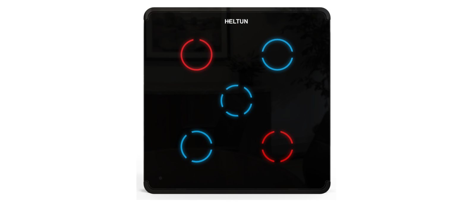
This is the user manual for the HELTUN HE-TPS04 Advanced Programmable Touch Panel Switch. The HE-TPS04 brings ‘Impossibly Smart’ capabilities to your home lighting, electric outlets, or motorized blinds, door locks, gates, and valves. It replaces an existing in-wall switch and brings over-the-Internet monitoring, control, and advanced programmability to four connected devices. Quarto is ‘Impossibly Thin’ on the wall yet packed with features to provide the ultimate control and convenience.
Controls up to four systems with two different power sourcesThanks to Quarto’s four-channel relays it can manage either: 1) up to four On/Off devices, 2) two On/Off devices and one bidirectional motor, or 3) two bidirectional motors. Two independent relay channel inputs allow control of systems with different power sources or use of relay outputs as dry contacts. Each relay can be loaded up to 5 Amps. Connects to Z-Wave lights and dimmersQuarto is an excellent choice for managing lighting systems. It allows connection to Z-Wave™ lights and dimmers controlling both On and Off, as well as smooth brighten (Up) and smooth dim (Down) states. Dimmer levels can be tied to Quarto’s button backlights to provide feedback of connected light state (On/Off).Controls motorized devicesQuarto can also be used to manage motorized systems like shades/blinds, driveway gates, water valves, windows and door locks. It also allows association with relay switches to control opening and closing of connected motorized devices. If door/window sensors are installed, they may be associated with Quarto backlights, enabling them to indicate device state (Open/Closed).Touch panel buttons have multiple functionsQuarto has four high sensitivity capacitive touch buttons with two-color backlights (red/blue) for each. 10 backlight brightness levels can be configured manually or set to automatically adjust to ambient light conditions making them always easy to see. Each button can be configured to control relay output state (#1-4) in any of nine different modes.Five ways to trigger programmed scenariosAn onboard Real Time Clock (RTC) enables Quarto to trigger scenarios where connected devices are set to a schedule. Another powerful feature lets Quarto trigger connected device scenarios when temperature, humidity, or light sensor values change. Quarto buttons may also directly trigger scenarios on controller — with each backlight indicating scene status.Know how much energy you useQuarto can determine how much energy is used by connected devices any particular day, week, or month. Just specify the consumption of the load in watts for each relay channel and the device logic will calculate total consumption relative to the time since the output was in the ‘ON’ state.Based on the latest Z-Wave platformQuarto integrates a Z-Wave Plus™ v2 700 platform module allowing it to be used with Z-Wave home automation systems. It supports Z-Wave ‘S0’ and ‘S2’ security protocols, Smart Start technology, and can be connected (“associated”) to other Z-Wave devices, such as relays, motor controllers, dimmers, etc.
Technical Specifications
- Front frame (on wall) dimensions: 89mm (H) х 89mm (W) х 9mm (D)
- Rear electronics package dimensions: 53mm (H) х 53mm (W) х 28mm (D)
- Materials: Tempered glass display/body, Flame retardant plastic
- 4 frame colors: White, Matte Black, Silver, Chrome
- 6 glass colors: White, Black, Yellow, Green, Red, Blue
- 4 capacitive-touch buttons
- Red and Blue LED backlights for each button
- 10 brightness levels (adjustable) for each button backlight
- 4 channel relay outputs, resistive load up to 5A each
- 2 independent relays inputs, dry contact
- Operating temperature: 0°С to +50°С
- Power supply: 85-265VAC 50Hz/60Hz or 24-48VDC
- Power consumption: 1W
- HELTUN Advanced Zero-Cross relay switching technology
- Relay lifetime: 100.000 switches
- Internal ambient light sensor
- Internal temperature sensor
- Measurement range: –30°C to +80°C
- Accuracy: ±0.5°C
- Internal humidity sensor
- Measurement range: 0% to 80%RH
- Accuracy: ±3.0%RH
- IP class: IP21
- Z-Wave Plus V2 SDK: V7.11
- Z-Wave module: ZGM130S
- Requires mounting to flush electrical junction box: round or square type – min. depth 40mm
Functions & Features
- Options for Inclusion/Exclusion to/from Z-Wave network
- Non-Secure o S0 Secure
- S2 Unauthorized, S2 Authorized with Key
- Association control of Z-Wave devices in the network • Schedule Mode
- Motorized device control (roller shutter mode)
- Each of four buttons can control any relay output
- Up to four different relay channels can be controlled by one button
- Each button can be set up to control devices from associated groups
- Each button backlight & relay outputs can be managed by a gateway or associated device
- Each button can trigger scenes
- Each button backlight can indicate a scene, or associated device state
- Any channel may be excluded from control
- Nine modes for each button:1. Momentary2. Momentary Reversed3. Momentary Toggle4. Toggle5. Switch ON Only6. Switch OFF Only7. Timer (ON to OFF)8. Timer Reversed (OFF to ON)9. Two-Relay Inverse
- Adjustable periodic measurements from:
- Internal temperature sensor
- Internal humidity sensor
- Internal ambient light sensor o Energy consumption meter
- Calibration of Internal Room Air Temperature Sensor
- Brightness control of button backlight:
- Automatic adjustment (depending on ambient light)
- Manual adjustment (10 levels).
- Backlight standby mode (different brightness for active and inactive states)
- Backlight blinking function (for easy identification among other Z Wave devices)
- Backlight colors invert
- Software energy consumption logic
- Factory reset function
- Smart Start technology for quick addition to Z-Wave networks
- OTA (Over The Air) encrypted firmware update
Installation
HELTUN recommends the HE-TPS04 touch panel switch be installed by a licensed electrician in a manner that conforms to local regulations and building codes. Provide these instructions to the licensed electrician who is installing the HE-TPS04.Note: It is not recommended to install the device in rooms with high humidity such as bathroom or sauna.
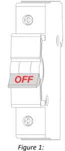
WARNING: Electrical power must be switched off during installation.
- Placement of the HE-TPS04 is of utmost importance for proper operation and must be away from sunlight and sources of direct heat. We recommend installing the HE-TPS04 approximately 1.5 meters above the floor.
- Remove the touch panel unit and backplate of the HE-TPS04 from the packaging.
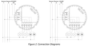
- FIRST ENSURE THE POWER IS OFF at the main circuit breaker (Fig. 1), and then test the wires with a probe or multimeter to verify. Insert the power wires to the HE-TPS04 “POWER” terminal by inserting a small Phillips-head screwdriver in the slot beneath each terminal and unscrew to open. Follow Fig. 2: Connection Diagram and instructions below:Power wires: for AC power (85-265VAC) connect Line & Neutral wires to L & N terminals labeled “POWER” (Fig 2. left diagram). For DC power (24-48VDC) connect “+” wire to terminal N and “-” wire to terminal L (Fig 2. right diagram).Source 1 wire: connect the required power source for relay 1 (OUT-1) and relay 2 (OUT-2) to the terminal labeled “IN 1-3”.Source 2 wire: connect the required power source for relay 3 (OUT-4) and relay 4 (OUT-5) to the terminal labeled “IN 4-5”.Loads: connect the required loads to the relay output terminals labeled “OUT-1”, “OUT-2”, “OUT-4”, “OUT-5”.Note: HELTUN recommends installing cord terminals (electric wire ferrule) on the ends of wires before connecting them to the HE-TPS04 outputs (various colors terminals are included in the packaging).

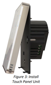
- Make sure the HE-TPS04 backplate is oriented on the wall with the word “TOP” pointed upwards. Then secure the backplate onto the electrical junction box using the four screws provided (do not overtighten). Once the backplate is secured onto the wall, assemble the HE-TPS04 touch panel unit onto the backplate by first carefully aligning the two top snap connectors (Fig. 3), and then gently pushing the entire display unit until it ‘snaps’ into position all the way around.
- Next, switch ON the main power at the circuit breaker. The HE TPS04 will start up with original default factory settings (all button backlights will indicate red).
- Remove the clear protective film from the touch panel unit and frame by pulling on the top right-hand orange color tabs.Note: Zero-Cross technology is unavailable if the device operates using DC voltage (24- 48VDC).
Disassembly
- To disassemble, ENSURE POWER IS SWITCHED OFF at the main circuit breaker AND ALL BUTTON BACKLIGHTS ARE OFF.
- To remove the HE-TPS04 touch panel unit, grasp firmly at the bottom and pull backwards while tilting outwards until all tabs are disconnected.
- Remove screws from backplate and disconnect the wires by inserting a small Phillips-head screwdriver into the slot beneath of each wire and turning counter-clockwise to release.
Factory Reset
To reset the HE-TPS04 to factory defaults, simultaneously press the two bottom buttons and hold for 6 seconds. If successful, all buttons will turn OFF then the device will reboot.The factory reset will change all the Parameters to their original factory default values (including Z-Wave frequency) and will also Exclude the device from any Z-Wave network.Note: Please use Factory Reset only when the primary network controller is missing or otherwise inoperable.
Z-Wave Network
The HE-TPS04 may be operated in any Z-Wave network with other Z Wave certified devices from other manufacturers. The HELTUN HE-TPS04 will act as a ‘repeater’ (i.e. ‘range extender’) for other devices regardless of manufacturer or brand to increase the reliability of the overall network.
Adding to Z-Wave network
To add the HE-TPS04 into a Z-Wave network (i.e. “Inclusion”), do the following:
- Start the Inclusion Mode from the gateway/controller.
- To start the inclusion process on the HE-TPS04, simultaneously press the two upper touch buttons and hold them for three seconds.
- All buttons will then sequentially blink blue – red.
- If the inclusion has been successful, all buttons will turn blue for three seconds.
- If the inclusion was not successful, all buttons will turn red for three seconds. In that case repeat the inclusion process.
Note: For correct operating in Fibaro gateways, the Single Channel Association should be removed from the device LifeLine (EndPoint 0 Group 1).
Removing from Z-Wave network
To remove the HE-TPS04 from a Z-Wave network (i.e. “Exclusion”), do the following:
- Start the Exclusion Mode from the gateway/controller.
- To start the exclusion process on the HE-TPS04, simultaneously press the two upper touch buttons and hold them for three seconds.
- All buttons will sequentially blink blue – red.
- If the exclusion has been successful, all buttons will turn red for three seconds.
- If the exclusion was not successful, all buttons will turn blue for three seconds. In that case repeat the exclusion process.Note: If the HE-TPS04 has previously been part of a Z-Wave network and has not been Excluded since, inclusion is not possible without first performing an Exclusion or Factory Reset procedure.
Security
S0, S2 unauthorized, and S2 authorized Inclusion Modes are supported. If you use the S2 authorized Inclusion Mode the security key should be used during the inclusion process. Security key is the first 5 digits of DSK (device DSK is printed on the HE-TPS04 back panel plus on the Security Card included in the packaging). Note: Be sure to save this key. Without the key, it is impossible to perform an inclusion in S2 authorized mode.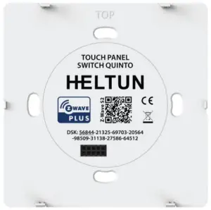
SmartStart
SmartStart-enabled products can be added to a Z-Wave network by scanning the Z-Wave QR Code shown on the product with gateways/controllers that allow for SmartStart inclusion. In this case, no further action will be required and the SmartStart product will be added automatically within ten minutes of being turned on in the vicinity of a network. To add the HE-TPS04 to a Z-Wave network using SmartStart:
- Input the HE-TPS04 DSK code to the controller’s Node Provisioning List (or scan the QR code).
- Power on the device.
- Wait for the inclusion process to complete.
- Successful adding” will be confirmed by a message on the Z-Wave controller.
Note: The device DSK and QR code are printed on the HE-TPS04 back panel plus on the Security Card included in the HE-TPS04 packaging.
Firmware OTA Update
To wirelessly update the HE-TPS04 firmware, follow these steps:
- Check the device current firmware version in the gateway/controller.
- Start the process from the Z-Wave gateway/controller.
- Download the latest firmware that corresponds to the HE-TPS04 (see support.heltun.com)
- Set the main controller in Firmware OTA (“over-the-air”) Update Mode (see the gateway/controller manual).
- As soon as the Firmware update begins, all buttons will sequentially blink blue-red (this will take a few minutes).
- When the Firmware has updated, all button backlights will turn blue then turn off for two seconds and the HE-TPS04 will reboot.
- When the update has been completed, the HE-TPS04 will return to normal operation.
- If desired, verify the update was successful by checking firmware version from the gateway/controller
Z-Wave Plus v2 Specifications
Generic Device Class: GENERIC_TYPE_WALL_CONTROLLER Specific Device Class: SPECIFIC_TYPE_NOT_USED
Supported Command Classes
| Command Class | Version | Required Security Class |
| Z-Wave Plus Info | V2 | none |
| Association | V2 | highest granted (S2 Authenticated, S2 Unauthenticated or S0) |
| Association Group Info | V3 | highest granted (S2 Authenticated, S2 Unauthenticated or S0) |
| Multi Channel Association | V3 | highest granted (S2 Authenticated, S2 Unauthenticated or S0) |
| Multi Channel | V4 | highest granted (S2 Authenticated, S2 Unauthenticated or S0) |
| Switch Binary | V2 | highest granted (S2 Authenticated, S2 Unauthenticated or S0) |
| Central Scene | V3 | highest granted (S2 Authenticated, S2 Unauthenticated or S0) |
| Sensor Multilevel | V11 | highest granted (S2 Authenticated, S2 Unauthenticated or S0) |
| Meter | V5 | highest granted (S2 Authenticated, S2 Unauthenticated or S0) |
| Clock | V1 | highest granted (S2 Authenticated, S2 Unauthenticated or S0) |
| Transport Service | V2 | none |
| Security 0 | V1 | none |
| Security 2 | V1 | none |
| Version | V3 | highest granted (S2 Authenticated, S2 Unauthenticated or S0) |
| Manufacturer Specific | V2 | highest granted (S2 Authenticated, S2 Unauthenticated or S0) |
| Device Reset Locally | V1 | highest granted (S2 Authenticated, S2 Unauthenticated or S0) |
| Powerlevel | V1 | highest granted (S2 Authenticated, S2 Unauthenticated or S0) |
| Supervision | V1 | none |
| Indicator | V3 | highest granted (S2 Authenticated, S2 Unauthenticated or S0) |
| Configuration | V4 | highest granted (S2 Authenticated, S2 Unauthenticated or S0) |
| Application Status | V1 | none |
| Firmware Update Meta Data | V5 | highest granted (S2 Authenticated, S2 Unauthenticated or S0) |
| Basic | V2 | highest granted (S2 Authenticated, S2 Unauthenticated or S0) |
| Meter Type | Scale | Rate Type | Precision | Size |
| Electric [0x01] | Electric_kWh [0x00] | Import [0x01] | 2 | 4 |
| Electric [0x01] | Electric_W [0x02] | Import [0x01] | 0 | 2 |
Associations
Association enables the HE-TPS04 to control other Z-Wave devices over the network. The HE-TPS04 has 9 Endpoints and 17 Association Groups. Each Association Group (except group 1) may include one other device from different brands and/or manufacturers.
EndPoint 0 Groups:
The Root Device (EndPoint 0) of HE-TPS04 has 17 association groups Group 1 – “Lifeline”: reports full state of the device and is used to communicate with the Z-Wave gateway. The group supports one Node. Note: It is not recommended to modify this group.Note: For correct operating in Fibaro gateways, the Single Channel Association should be removed from the device LifeLine (EndPoint 0 Group 1).Group 2 – “Touch 1 Basic Set”: is assigned to touch N1. Is used to send Basic Set ON (value 255) and Basic Set OFF (value 0) commands to the associated devices. Max supported nodes: 1.Group 3 – “Touch 1 Multilevel Set”: is assigned to touch N1. It sends MULTILEVEL SWITCH command class frame when touch N1 was held. Is used to send UP/DOWN command to the associated devices. Max supported nodes: 1.Group 4 – “Touch 2 Basic Set”: is assigned to touch N2. Is used to send Basic Set ON (value 255) and Basic Set OFF (value 0) commands to the associated devices. Max supported nodes: 1.Group 5 – “Touch 2 Multilevel Set”: is assigned to touch N2. It sends MULTILEVEL SWITCH command class frame when touch N2 was held. Is used to send UP/DOWN command to the associated devices. Max supported nodes: 1.Group 6 – “Touch 3 Basic Set”: is assigned to touch N3. Is used to send Basic Set ON (value 255) and Basic Set OFF (value 0) commands to the associated devices. Max supported nodes: 1.Group 7 – “Touch 3 Multilevel Set”: is assigned to touch N3. It sends MULTILEVEL SWITCH command class frame when touch N3 was held. Is used to send UP/DOWN command to the associated devices. Max supported nodes: 1.Group 8 – “Touch 4 Basic Set”: is assigned to touch N4. Is used to send Basic Set ON (value 255) and Basic Set OFF (value 0) commands to the associated devices. Max supported nodes: 1.Group 9 – “Touch 4 Multilevel Set”: is assigned to touch N4. It sends MULTILEVEL SWITCH command class frame when touch N4 was held. Is used to send UP/DOWN command to the associated devices. Max supported nodes: 1.Group 10 – “LED 1 Basic Set”: is assigned to LED N1. Is used to send Basic Set ON (value 255) and Basic Set OFF (value 0) commands to the associated devices. Max supported nodes: 1.Group 11 – “LED 2 Basic Set”: is assigned to LED N2. Is used to send Basic Set ON (value 255) and Basic Set OFF (value 0) commands to the associated devices. Max supported nodes: 1.Group 12 – “LED 3 Basic Set”: is assigned to LED N3. Is used to send Basic Set ON (value 255) and Basic Set OFF (value 0) commands to the associated devices. Max supported nodes: 1.Group 13 – “LED 4 Basic Set”: is assigned to LED N4. Is used to send Basic Set ON (value 255) and Basic Set OFF (value 0) commands to the associated devices. Max supported nodes: 1.Group 14 – “Relay 1 Basic Set”: is assigned to relay N1. Is used to send Basic Set ON (value 255) and Basic Set OFF (value 0) commands to the associated devices. Max supported nodes: 1.Group 15 – “Relay 2 Basic Set”: is assigned to relay N2. Is used to send Basic Set ON (value 255) and Basic Set OFF (value 0) commands to the associated devices. Max supported nodes: 1.Group 16 – “Relay 3 Basic Set”: is assigned to relay N3. Is used to send Basic Set ON (value 255) and Basic Set OFF (value 0) commands to the associated devices. Max supported nodes: 1.Group 17 – “Relay 4 Basic Set”: is assigned to relay N4. Is used to send Basic Set ON (value 255) and Basic Set OFF (value 0) commands to the associated devices. Max supported nodes: 1.
EndPoints 1-8 Groups:
Group 1 – “Lifeline”: reports state of the device and used to communicate with the Z-Wave gateway. The group supports one Node. Note: It is not recommended to modify this group.Group 2 – “Basic Set”: Is used to send Basic Set ON (value 255) and Basic Set OFF (value 0) commands to the associated devices. The group supports one Node and it is mapped to EndPoint 0 groups.Here is a truth table for EndPoints 1-8 groups mapping to the root device (EndPoint 0) groups:
| EndPoints 1-10 groups | Root (EndPoint 0) groups |
| Endpoint 1, Group 2 – “LED 1 Basic Set” | Group 10 – “LED 1 Basic Set” |
| Endpoint 2, Group 2 – “LED 2 Basic Set” | Group 11 – “LED 2 Basic Set” |
| Endpoint 3, Group 2 – “LED 3 Basic Set” | Group 12 – “LED 3 Basic Set” |
| Endpoint 4, Group 2 – “LED 4 Basic Set” | Group 13 – “LED 4 Basic Set” |
| Endpoint 5, Group 2 – “Relay 1 Basic Set” | Group 14 – “Relay 1 Basic Set” |
| Endpoint 6, Group 2 – “Relay 2 Basic Set” | Group 15 – “Relay 2 Basic Set” |
| Endpoint 7, Group 2 – “Relay 3 Basic Set” | Group 16 – “Relay 3 Basic Set” |
| Endpoint 8, Group 2 – “Relay 4 Basic Set” | Group 17 – “Relay 4 Basic Set” |
Gateway compatibility requirement:
In order to make a reliable connection and data exchange with the gateway make sure that the gateway/controller is multi-channel capable. The gateway/controller lifeline association should be configured as a “multi-channel association.” Some Gateways need this option to be manually configured.Note: Fibaro Home Center 2: In order to enable correct communications between a Fibaro Gateway/Controller and the HE-TPS04, the lifeline association should be configured as a “multi-channel association.” Make sure that only the Multi-channel association check box is selected under Device > Settings > Advanced > Setting Association > Group1 tab (lifeline).Note: By default, there are two checkboxes for Single-channel and Multi-channel associations. Please deselect the checkbox under Single-channel associations.
Touch Panel Operation
The HE-TPS04 has four relays, four touch buttons and two-color (red and blue) backlights for each button.
- Each relay can be controlled by any touch button or via a Z-Wave network (using a Z-Wave gateway).
- Each touch button can be configured to control any relay output state (from one to four) in the modes below:
- MOMENTARY: When the button is held the relay output is ON, as soon as the button is released the relay output state changes to OFF (see Parameters 41-44 settings).
- MOMENTARY REVERSED: When the button is held the relay output is OFF, as soon as the button is released the relay output state changes to ON (see Parameters 41-44 settings).
- MOMENTARY TOGGLE: When the button is held, the relay output inverts state (from ON to OFF or from OFF to ON), as soon as the button is released the relay output inverts state again (see Parameters 41-44 settings).
- TOGGLE: On the button each press the relay output inverts state (from ON to OFF or from OFF to ON) (see Parameters 51-54 settings).
- SWITCH ON ONLY: On the button press the relay output switches to ON state only (see Parameters 51-54 settings). Note: If the relay output is already in ON state, nothing will change. Tip: This function is useful when there is a need to control the lighting with two buttons, one to turn ON, the other to turn OFF.
- SWITCH OFF ONLY: On the button press the relay output switches to OFF state only (see Parameters 51-54 settings). Note: If the relay output is already in OFF state, nothing will change. Tip: This function is useful when there is a need to control the lighting with two buttons, one to turn ON, the other to turn OFF.
- TIMER (ON to OFF): On the button press the relay output switches to ON for the specified time, then reverts to OFF (see Parameters 51-54 settings). Note: Time can be configured from 0 sec to 43200 sec (12 hours). Tip: This function is useful for running motor for a short time (e.g. open/close garage doors, blinds, etc.).
- TIMER REVERSED (OFF to ON): On the button press the relay output switches to OFF for the specified time then reverts to ON (see Parameters 51-54 settings).Note: Time can be configured from 0 sec to 43200 sec (12 hours). Tip: This function is useful for switching OFF security system or door lock for a short time.
- TWO-RELAY INVERSE MODE: When two relays are in Inverse Mode, after pressing the button the corresponding relay (connected to that button) inverts its state (from ON to OFF, or from OFF to ON) and the second relay will be switched OFF. The above mentioned two relays are defined according to Parameters 101 or 10 102 (e.g. if “24” is set as the Parameter value, it means the second relay and fourth relay will never be ON at the same time).Note: In this mode both relays cannot be switched ON simultaneously and first one relay switches OFF, then another switches ON.Tip: This function can be used for motors direction control.
- ROLLER SHUTTER: When two relays are connected to the same button and are Inverse Mode, they will operate in ‘roller shutter’ mode. After entering this mode, relays will switch to OFF state, and never switch ON simultaneously. The relay behavior is as follows for this four-touch cycle (in this order):
- press: the first relay will be switched ON and the second relay will be switched OFF
- press: both relays will be switched OFF
- press: the second relay will be switched ON and the first relay will be switched OFF
- press: both relays will be switched OFF Tip: This can be used to control motor directions with one button only. Each touch button can also be used to run scenarios or change modes in the connected gateway or associated devices.
- Each button’s backlight can be configured as follows to indicate:
- Relay output state
- Touch button state
- Mode state in connected gateway
- Associated device stateNote: It is possible to choose the light color for each state: red for ON and blue for OFF, or blue for ON and red for OFF (see Parameter 30 settings).If the HE-TPS04 is included to the Z-Wave gateway, the scene controller, light, temperature & humidity sensors info, and eight binary switches will appear. The scene controller indicates which button was pressed, held, or released and allows the running of scenes on the Z-Wave gateway. The first four binary switches indicate and control the button backlight. The remaining four binary switches indicate and control the relay output.
Settings (available through Z-Wave network)
All configuration parameters are accessed through Z-Wave COMMAND_CLASS_CONFIGURATION
Parameters List & Factory Defaults
| Number | Size | Description | Default Value | Available Values |
| 1 | 1 byte | Frequency Region | Read Only | 0 … 9 |
| 2 | Reserved by the manufacturer | |||
| 3 | 4 bytes | Hardware and Software Versions | Read Only | XXYYZZ |
| 4 | 4 bytes | Energy Consumption, kW | Read Only | Total consumption |
| 5 | 1 byte | Backlight brightness control | 0 | 0, 1 … 10 |
| 6 | 1 byte | Touch buttons sensitivity. 1 = Lowest; 10 = Highest | 6 | 1 … 10 |
| 7 | 1 byte | Relay 1 output NO or NC mode | 0 | 0, 1 |
| 8 | 1 byte | Relay 2 output NO or NC mode | 0 | 0, 1 |
| 9 | 1 byte | Relay 3 output NO or NC mode | 0 | 0, 1 |
| 10 | 1 byte | Relay 4 output NO or NC mode | 0 | 0, 1 |
| 11 | Reserved by the manufacturer | |||
| 12 | 2 bytes | Power of the Relay 1 load in W | 0 | 0…1100 |
| 13 | 2 bytes | Power of the Relay 2 load in W | 0 | 0…1100 |
| 14 | 2 bytes | Power of the Relay 3 load in W | 0 | 0…1100 |
| 15 | 2 bytes | Power of the Relay 4 load in W | 0 | 0…1100 |
| 16 | Reserved by the manufacturer | |||
| 17 | 1 byte | Air Temperature Calibration in °C, value X 10, e.g. 1.0°C=10 | 0 | -100 … 100 |
| 18 | Reserved by the manufacturer | |||
| 19 | 1 byte | Time correction by controller | 1 | 0, 1 |
| 20 | Reserved by the manufacturer | |||
| 21 | 1 byte | Week Day | 1 | 1, 2, 3, 4, 5, 6, 7 |
| 22 | 2 bytes | Time: Hour and Minutes | 0 | 0 … 2359 |
| 23-29 | Reserved by the manufacturer | |||
| 30 | 1 byte | Active state backlight color | 1 | 0, 1 |
| 31 | 1 byte | Backlight 1 control source | 1 | 0, 1, 2 |
| 32 | 1 byte | Backlight 2 control source | 1 | 0, 1, 2 |
| 33 | 1 byte | Backlight 3 control source | 1 | 0, 1, 2 |
| 34 | 1 byte | Backlight 4 control source | 1 | 0, 1, 2 |
| 35-40 | Reserved by the manufacturer | |||
| 41 | 1 byte | Hold control mode for touch button 1 | 2 | 0, 1, 2, 3, 4 |
| 42 | 1 byte | Hold control mode for touch button 2 | 2 | 0, 1, 2, 3, 4 |
| 43 | 1 byte | Hold control mode for touch button 3 | 2 | 0, 1, 2, 3, 4 |
| 44 | 1 byte | Hold control mode for touch button 4 | 2 | 0, 1, 2, 3, 4 |
| 45-50 | Reserved by the manufacturer | |||
| 51 | 1 byte | Click control mode for touch button 1 | 1 | 0, 1, 2, 3, 4, 5, 6 |
| 52 | 1 byte | Click control mode for touch button 2 | 1 | 0, 1, 2, 3, 4, 5, 6 |
| 53 | 1 byte | Click control mode for touch button 3 | 1 | 0, 1, 2, 3, 4, 5, 6 |
| 54 | 1 byte | Click control mode for touch button 4 | 1 | 0, 1, 2, 3, 4, 5, 6 |
| 55-60 | Reserved by the manufacturer | |||
| 61 | 1 byte | Relay 1 control source | 1 | 0, 1, 2, 3, 4 |
| 62 | 1 byte | Relay 2 control source | 2 | 0, 1, 2, 3, 4 |
| 63 | 1 byte | Relay 3 control source | 3 | 0, 1, 2, 3, 4 |
| 64 | 1 byte | Relay 4 control source | 4 | 0, 1, 2, 3, 4 |
| 65-70 | Reserved by the manufacturer | |||
| 71 | 2 bytes | Timer mode duration for button 1 | 0 | 0 to 43200 |
| 72 | 2 bytes | Timer mode duration for button 2 | 0 | 0 to 43200 |
| 73 | 2 bytes | Timer mode duration for button 3 | 0 | 0 to 43200 |
| 74 | 2 bytes | Timer mode duration for button 4 | 0 | 0 to 43200 |
| 75-100 | Reserved by the manufacturer | |||
|
101 |
1 byte |
Group 1 relay inverse mode |
0 |
0, 12, 13, 14, 21,
23, 24, 31, 32, 34, 41, 42, 43 |
|
102 |
1 byte |
Group 2 relay inverse mode |
0 |
0, 12, 13, 14, 21,
23, 24, 31, 32, 34, 41, 42, 43 |
| 103-110 | Reserved by the manufacturer | |||
| 111 | 4 bytes | Relay control scenario 1 | 0 | 0, 10000000 to
43112359 |
| 112 | 4 bytes | Relay control scenario 2 | 0 | 0, 10000000 to
43112359 |
| 113 | 4 bytes | Relay control scenario 3 | 0 | 0, 10000000 to
43112359 |
| 114 | 4 bytes | Relay control scenario 4 | 0 | 0, 10000000 to
43112359 |
| 115 | 4 bytes | Relay control scenario 5 | 0 | 0, 10000000 to
43112359 |
| 116 | 4 bytes | Relay control scenario 6 | 0 | 0, 10000000 to
43112359 |
| 117 | 4 bytes | Relay control scenario 7 | 0 | 0, 10000000 to
43112359 |
| 118 | 4 bytes | Relay control scenario 8 | 0 | 0, 10000000 to
43112359 |
| 119 | 4 bytes | Relay control scenario 9 | 0 | 0, 10000000 to
43112359 |
| 120 | 4 bytes | Relay control scenario 10 | 0 | 0, 10000000 to
43112359 |
| 121-140 | Reserved by the manufacturer | |||
| 141 | 1 byte | Consumption meter consecutive reporting interval, minutes | 10 | 1 … 120 |
| 142 | 1 byte | Consumption change report to send to controller | 1 | 0, 1 |
| 143 | 1 byte | Sensors consecutive reporting interval, minutes | 10 | 1 … 120 |
| 144 | 1 byte | Temperature difference to send to controller, value X 10 | 2 | 0, 1 … 100 |
| 145 | 1 byte | Humidity difference to send to controller, % | 2 | 0, 1 … 25 |
| 146 | 1 byte | Light sensor values difference to send to controller, % | 50 | 0, 10 … 99 |
| 147-170 | Reserved by the manufacturer | |||
| 171 | 1 byte | Touch control mode for associations with touch button 1 | 0 | 0, 1, 2 |
| 172 | 1 byte | Touch control mode for associations with touch button 2 | 0 | 0, 1, 2 |
| 173 | 1 byte | Touch control mode for associations with touch button 3 | 0 | 0, 1, 2 |
| 174 | 1 byte | Touch control mode for associations with touch button 4 | 0 | 0, 1, 2 |
Z-Wave Frequency
Parameter 01 – Frequency RegionThe HE-TPS04 has Z-Wave 700 series chip inside which allows to use the device in different Z-Wave frequencies. If there is a need to use the device in the frequency different from the factory default, change the value of this Parameter according to the frequency list below. Modification is possible only while the HE-TPS04 is not included to Z-Wave network.Note: The factory default frequency differs depending on which region the device was intended for sale in. Check the factory default frequency on the device plate or on the packaging.Note: Do not change this Parameter value if there is no special need. Note: If change the value of this Parameter, the frequency change will be applied only after removing the device from Z-Wave network (the device will automatically reboot).Note: The change of this Parameter will result in inability to control the device, if the device was included to the controller/gateway which supports only one frequency.Note: Resetting the device to factory default settings will revert the frequency to the factory default value.Note: In most of countries it is not allowed to use the frequency different from the frequency intended for that country.
Frequency list for different regions:
| 0: EU (868.4 MHz, 869.85 MHz)
1: US (908.4 MHz, 916.0 MHz) 2: ANZ (919.8 MHz, 921.4 MHz) 3: HK (919.8 MHz) 4: IN (865.2 MHz) |
5: IL (916.0 MHz)
6: RU (869.0 MHz) 7: CN (868.4 MHz) 8: JP (922.5 MHz, 923.9 MHz, 926.3 MHz) 9: KR (920.9 MHz, 921.7 MHz, 923.1 MHz) |
The full list of Z-Wave global regions where Z-Wave works is available at Z-Wave Global Regions SiLabs page.
Hardware & Software Versions
Parameter 03 – Hardware and Software Versions
This Parameter allows to check the hardware and firmware versions of the device. The Parameter returns value in the format XXYYZZ, where XX is Hardware Version, YY is Firm ware Major Version and ZZ is Firmware Minor Version. Note: This Parameter is read-only.
Power and Energy Consumption
Parameter 04 – Energy Consumption
This Parameter allows to check the Cumulative Energy Consumption (in kW) of the connected loads. HE-TPS04 monitors Real-Time and Cumulative power Energy Consumption of connected loads using advanced software logic which measures the consumption based on loads power value set in Parameters from 12 to 15. Cumulative Energy Consumption is the total electrical power being used by connected loads since the Parameter 04 value last reset. Power usage is calculated by the software using the values that were manually set when configuring Parameters 12-15, multiplied by the time tracked when the HE- TPS04corresponding output was in ON state. Real-Time Consumption and Cumulative Consumption are periodically reported to the Z-Wave controller according to the Parameter 141 and 142 settings.Note: This Parameter is read-only.
Resetting Cumulative Consumption memory:
The HE-TPS04 enables you to erase stored Consumption Data through the Z-Wave network as follows: 1. Make sure the HE-TPS04 is powered. 2. If not already done so, include the device into Z-Wave Gateway network. 3. Reset memory consumption data using the Reset Command in COMMAND_CLASS_METER (see the Gateway owner’s manual). Note: Turning the device main power off/on will not erase the consumption data as it is stored in nonvolatile memory.
Parameters 12-15 – Relay 1-4 Load Power in watt
These parameters are used to specify the loads power that are connected to the device outputs. Using your connected device’s power consumption specification (see associated owner’s manual), set the load in Watts for: Relay 1 (“OUT1”) in Parameter 12, Relay 2 (“OUT-2”) in Parameter 13, Relay 3 (“OUT-4”) in Parameter 14, Relay 4 (“OUT-5”) in Parameter 15. The factory default value is 0.Note: The range from 0 to 1100 watt can be selected.
The HE-TPS04 has two brightness levels for its buttons backlight: 1) Active Level – when a button is touched, its backlight becomes brighter, and 2) Inactive Level – after one second of inactivity, its backlight dims. The actual brightness level may be adjusted manually or automatically.
Parameter 05 – Brightness Control
The HE-TPS04 can adjust its buttons backlight brightness automatically depending on the illumination of the ambient environment and also allows to control it manually. Set the Parameter value to 0 to activate the Automatic Brightness Control or set from value 1 (lowest brightness) to 10 (highest brightness) for Manual Control. The factory default value is 0.
Touch Sensitivity
Parameter 06 – Touch Sensor Sensitivity Threshold
This Parameter allows the device Touch Button Sensitivity Threshold to be adjusted from level 1 (low sensitivity) to 10 (high sensitivity). The factory default value is 6. Note: Setting the sensitivity too high can lead to false touch detection. We recommend not changing this Parameter unless there is a special need to do so.
Outputs NO/NC Mode
Parameters 07-10 – Outputs NO/NC Mode
These Parameters determine the type of loads connected to the device relay outputs. The outputs type can be NO – normal open (no contact/voltage to switch the load OFF) or NC – normal close (output is contacted / there is a voltage to switch the load OFF). Choose the value 0 if NO contact type is required or value 1 if NC type is required. Set the value for Relay 1 (“OUT-1”) in Parameter 07, for Relay 2 (“OUT-2”) in Parameter 08, for Relay 3 (“OUT-4”) in Parameter 09, for Relay 4 (“OUT-5”) in Parameter 10. The factory default value is 0 (NO mode).
temperature Sensor Calibration
Parameter 17 – Air Temperature Calibration
This parameter defines the offset value for room air temperature. If the internal air temperature sensor is not correctly calibrated, then manual calibration can be made by adjusting the values up to ±10°C. This value will be added or subtracted from the internal air temperature sensor reading. The value of this Parameter should be x10, e.g. for 1.5°C set the value 15. The factory default value is 0
Time Configurations
Parameter 19 – Time Correction by Main Controller
If this Parameter value = 1 and the HE-TPS04 is connected to a Z-Wave gateway, the HE-TPS04 time and day will be periodically polled and corrected from the gateway. To switch off auto- correction set the Parameter value to 0. The factory default value is 1.
Parameter 21 – Day of the Week Manual Adjustment
This Parameter allows manual adjustment of the day of the week in case the HE-TPS04 is not connected to any ZWave gateway or auto correction is disabled (Parameter 19 value is 0). 1 = Monday, 2 = Tuesday, 3 = Wednesday, 4 = Thursday, 5 = Friday, 6 = Saturday, 7 = Sunday. The factory default value is 1.
Parameter 22 – Time Manual Adjustment
This Parameter allows manual adjustment of Time. The Parameter has the following format: HHMM, where HH is hours and MM is minutes. E.g. for 16:08 set the value 1608 and for 1:00 set the value 100.
Backlights Control Source
Choose the value “1” if you wish the backlight active state to be blue and the inactive state to be red (default). Choose the value “0” if you wish the backlight active state to be red, and the inactive state to be blue. The factory default value is 1.
0 – Backlight is disabled (both color LEDs are turned off)1 – Backlight is controlled by touch button (reflects the button state)2 – Backlight is controlled by gateway or associated device (the button state is ignored)Set the value for Button 1 in Parameter 31, for Button 2 in Parameter 32, for Button 3 in Parameter 33, for Button 4 in Parameter 34. The factory default value is 1.Note: If the backlight is disabled (the Parameter value is set to “0”), it is also impossible to control it from the gateway.
0 – Hold function is disabled1 – Operate like click2 – When the button is held the relay output state is ON, as soon as the button is released the relay output state changes to OFF (momentary switch).3 – When the button is held the relay output state is OFF, as soon as the button is released the relay output state changes to ON (momentary switch).4 – When the button is held or released the relay output state will toggle its state (ON to OFF or OFF to ON). Set the value for Button 1 in Parameter 41, for Button 2 in Parameter 42, for Button 3 in Parameter 43, for Button 4 in Parameter 44. The factory default value is 2Note: Regardless of this Parameter, the device will send scene notifications about the touch state (pressed, held, released) to the gateway.
0 – Press function disabled1 – Relay inverts state (toggles ON to OFF, OFF to ON) according to the relay state
2 – Relay inverts state (toggles ON to OFF, OFF to ON) according to the button backlight state.3 – Relay switches to ON state only4 – Relay switches to OFF state only5 – Timer: On>Off Mode: Relay output switches to ON state (contacts are closed) then after a specified time switches back to OFF state (contacts are open). The time is specified in Parameters 71-74.6 – Timer: OFF>ON Mode: Relay output switches to OFF state (contacts are open) then after a specified time switches back to ON state (contacts are closed). The time is specified in Parameters 71-74. Set the value for Button 1 in Parameter 51, for Button 2 in Parameter 52, for Button 3 in Parameter 53, for Button 4 in Parameter 54. The factory default value is 1
Relays Mode
0 – Controlled by gateway or associated device1 – Controlled by touch button N1 (Top Left)2 – Controlled by touch button N2 (Top Right)3 – Controlled by touch button N3 (Bottom Left)4 – Controlled by touch button N4 (Bottom Right) Set the value for Relay 1 (“OUT-1”) in Parameter 61, for Relay 2 (“OUT-2”) in Parameter 62, for Relay 3 (“OUT-4”) in Parameter 63, for Relay 4 (“OUT-5”) in Parameter 64.Factory default value: each relay corresponds to its button (e.g. for Relay 3 the default value is touch button N3).
Parameters 71-74 – Relay Timer mode duration
These Parameters specify the duration in seconds for the Timer mode (values 5 or 6 in Parameters 51-54 respectively). Press the button and the relay output goes to ON/OFF for the specified time then changes back to OFF/ON. This function can be used to open/close garage doors, blinds, curtains, etc. or to turn attached devices like door lock or security OFF for a short time. The time values can be configured from 0 sec to 43200 sec (12 hours). Set the value for Relay 1 (“OUT1”) in Parameter 71, for Relay 2 (“OUT-2”) in Parameter 72, for Relay 3 (“OUT-4”) in Parameter 73, for Relay 4 (“OUT5”) in Parameter 74. The factory default value is 0.Note: If the parameter value is set to “0” it will operate as a short contact (about 0.5 sec).
Parameters 101, 102 – Relay Inverse Mode
The values in this Parameter will specify the relay numbers that will operate in inverse mode. For this purpose, the value will be encoded as a 2-digit number “AB” where “A” is the number of the first relay, and “B” is number of the second relay. For example, if the Parameter value is “24” or “42” it means the relays N2 and N4 will operate in inverse mode. Relays can operate in an inverse mode in two different ways:1. When the first and the second relays are connected to two different buttons. In this case, after pressing a button, the corresponding relay connected to that button will toggle its state (ON to OFF or OFF to ON), and the other relay will be switched OFF.2. When two relays are connected to the same button. In this case, the relays will operate in roller shutter mode and their behavior will follow these four cycles:
- 1st press of button: the first relay will be switched ON, the second relay will be switched OFF
- 2nd press of button: both relays will be switched OFF
- 3rd press of button: the second relay will be switched ON, the first relay will be switched OFF
- 4th press of button: both relays will be switched OFFNote: In this mode, both relays cannot be switched ON at the same time (i.e. simultaneously).Note: Switching OFF one relay will always operate before switching ON another relay to prevent both relays from being ON at the same time.Note: Two groups of inverse relays can be specified, one group in Parameter 101, another group in Parameter 102.
Scenarios
Scenarios can be created that allow connected devices to be triggered by a sensor or onboard Real Time Clock (RTC). The HE-TPS04 has built-in temperature, humidity, and ambient temperature sensors and includes a very flexible, user friendly interface for customizing scenarios. In addition to the physical sensors, time may be used as a control source. The user should configure the output number, state, sensor type, state change condition, and threshold in the Parameters (from 111 – 120) which will trigger the scenes.
Parameters 111-120- Relays Control by Sensors
In these Parameters, the relay state changes depending on sensor threshold value. For these configurations, Parameter values are encoded as 8-digit numbers (ABCDEFGH):
A = Relay number (1 through 4)B = Control Mode0-Temperature Sensor,1-Humidity Sensor,2-Light Sensor,3-Time controlC = State change relative to value in EFGH Condition Value fields (see below)0-Equal or lower than1-Equal or higher thanD: State Change,0-Switch OFF1-Switch ON
EFGH: Condition Value“Sensor Value” for Control modes 0, 1, and 2, or “Time” for Control mode 3.If Temperature sensor has been chosen as a source in the control mode, the value should be x10, e.g. for 24.5°C use the value 0245.If Time control has been chosen as a source in the control mode, the device logic will process values EFGH from 0 to 23:59 (in time measure), all other values will be ignored.EF represents Hour (0 through 23), GH represents Minutes (0 through 59).
All other numbers are reserved and will not affect the operation. To disable this option simply set this Parameter to 0.The factory-default value: “0”Example: Parameter value 12010050 means A=1 (relay 1 output), B=2 (light sensor), C=0 (value lower than), D=1 (switch relay On), EFGH=0050. In this case if light sensor reading drops below 50 lum, the relay 1 output will be switched On.Note: The relays still can be controlled manually using touch buttons according to Parameters 41-44 and 51-54 or via gateway.Note: The logic will implement the operation when the sensor value crosses the value in the Parameter. Meaning, that if the logic switches ON the relay and you manually switch it OFF, the relay will switch ON next time when the value crosses the set Parameter
Sensors Report Interval
Parameter 141 – Energy Consumption Meter Consecutive Report Interval
When the device is connected to the Z-Wave gateway (controller), it periodically sends to the gateway reports from its energy consumption meter even if there is no change in the value. This Parameter defines the interval between consecutive reports of real time and cumulative energy consumption data to the gateway. The value can be adjusted from 1 min to 120 min. The factory default value is 10 min.Note: If the consumption changes, the device will send the report to the gateway regardless of this Parameter value (the report will be sent according to value in Parameter 142).Note: It is not recommended to reduce the value of this Parameter in order not to increase the traffic on your network. We recommend to reduce the value of this Parameter only in case of poor connection, when reports from the device does not always reach the gateway.
Parameter 142 – Control Energy Consumption Report
This Parameter determines if the consumption change will resulting in the consumption report being sent to the gateway. Use the value 0 if there is a need to stop sending the reports and value 1 to activate reports. The factory default value is 1.Note: When the device is turning ON, the consumption data will be sent to the gateway once, even if the value of this Parameter is 0.
Parameter 143 – Sensors Consecutive Report Interval
When the device is connected to the Z-Wave gateway (controller), it periodically sends to the gateway reports from its room temperature, humidity and light sensors even if there are not changes in the values. This Parameter defines the interval between consecutive reports. The value can be adjusted from 1 min to 120 min. The factory default value is 10 minNote: If the sensor readings change, the device will send the report to the gateway regardless of this Parameter value (the report will be sent according to values in Parameters 144, 145 and 146).Note: It is not recommended to reduce the value of this Parameter in order not to increase the traffic on your network. We recommend to reduce the value of this Parameter only in case of poor connection, when reports from the device does not always reach the gateway.
Parameter 144 – Air Temperature Sensors Report Threshold
This Parameter determines the change in temperature level (in °C) resulting in temperature sensor report being sent to the gateway. The value of this Parameter should be x10, e.g. for 0.4°C use value 4. From 0.1°C (value 1) to 10°C (value 100) can be selected. Use the value 0 if there is a need to stop sending the reports. The factory default value is 2 (0.2°C).Note: When the device is turning ON, the sensor data will be sent to the gateway once, even if the value of this Parameter is 0.Note: It is not recommended to decrease the value of this Parameter, in order not to increase the load on your Z-Wave network traffic.
Parameter 145 – Humidity Sensor Report Threshold
This Parameter determines the change in humidity level in % resulting in humidity sensors report being sent to the gateway. From 1% to 25% can be selected. Use the value 0 if there is a need to stop sending the reports. The factory default value is 2.Note: When the device is turning ON, the sensor data will be sent to the gateway once, even if the value of this Parameter is 0.Note: It is not recommended to decrease the value of this Parameter, in order not to increase the load on your Z-Wave network traffic.
Parameter 146 – Light Sensor Report Threshold
This Parameter determines the change in the ambient environment illuminance level resulting in a light sensors report being sent to the gateway. From 10% to 99% can be selected. Use the value 0 if there is a need to stop sending the reports. The factory default value is 50.Note: When the device is turning On, the sensor data will be sent to the gateway once, even if the value of this Parameter is 0.Note: It is not recommended to decrease the value of this Parameter, in order not to increase the load on your Z-Wave network traffic.
Association Commands Configuration
Parameters 171-174 – Associations Mode
These Parameters are intended for use when Multilevel Switch Group Associations (Groups 3, 5, 7, 9) have been activated. They define the logic of values changing if one of the touch buttons has been held for more than one second. They are useful options for controlling dimmers or roller shutter devices in the following three ways:“0” – On each hold event, “UP (brighten)” and “DOWN (dim)” command will be alternately sent to associated devices.“1” – On each hold event, the “UP (brighten)” command will be sent to associated devices.“2” – On each hold event, the “DOWN (dim)” command will be sent to associated devices.Set the value for Group 3 (Touch 1 association) in Parameter 171, for Group 5 (Touch 2 association) in Parameter 172, for Group 7 (Touch 3 association) in Parameter 173, for Group 9 (Touch 4 association) in Parameter 174. The factory-default value: 0.
Limited Warranty
HELTUN warrants this product to be free from defects in workmanship or materials, under normal use and service, for a period of one (1) year from the date of purchase by the consumer (“Warranty Period”). HELTUN will extend this Warranty Period to three (3) years from the date of consumer purchase for any consumer who registers his/her product with HELTUN at this website page: bonus.heltun.com. This Limited Warranty applies only to the first end-user of the product and is not transferable.
If during the Warranty Period the product is determined to be defective or malfunctions due to workmanship or materials, HELTUN, at HELTUN’s option, shall either repair or replace the defective product. If the product is defective, (i) return it with dated proof of purchase to the place it was purchased; or (ii) contact HELTUN Customer Care by email at [email protected] HELTUN Customer Care will make the determination whether the product should be returned or whether a replacement product will be sent to you.
EXCEPT AS MAY BE OTHERWISE PROVIDED BY APPLICABLE LAW, THIS LIMITED WARRANTY IS IN LIEU OF ALL OTHER COVENANTS AND WARRANTIES, EITHER EXPRESS OR IMPLIED, INCLUDING WITHOUT LIMITATION, ANY IMPLIED WARRANTIES OF MERCHANTIBILITY OR FITNESS FOR A PARTICULAR PURPOSE, OR NON-INFRINGEMENT. HELTUN MAKES NO OTHER WARRANTIES, EXPRESS OR IMPLIED.
THIS LIMITED WARRANTY DOES NOT COVER REMOVAL OR REINSTALLATION COSTS. THIS LIMITED WARRANTY SHALL NOT APPLY IF IT IS SHOWN BY HELTUN THAT THE DEFECT OR MALFUNCTION WAS CAUSED BY DAMAGE DONE BY A CONSUMER INCLUDING DURING INSTALLATION. THIS LIMITED WARRANTY IS VOID IF DEFECT(S) RESULT FROM A FAILURE TO HAVE THIS PRODUCT INSTALLED PROPERLY.
HELTUN’S SOLE RESPONSIBILITY AND THE CONSUMER’S SOLE REMEDY UNDER THIS LIMITED WARRANTY SHALL BE TO REPAIR OR REPLACE THE PRODUCT WITHIN THE TERMS STATED ABOVE. HELTUN SHALL NOT BE LIABLE FOR ANY LOSS OR DAMAGE OF ANY KIND, INCLUDING ANY INCIDENTAL OR CONSEQUENTIAL DAMAGES RESULTING, DIRECTLY OR INDIRECTLY, FROM ANY BREACH OF ANY WARRANTY, EXPRESS OR IMPLIED, OR ANY OTHER FAILURE OF THIS PRODUCT. IN NO EVENT SHALL HELTUN’S LIABILITY EXCEED THE AMOUNT ACTUALLY PAID FOR THE PRODUCT WHETHER SUCH LIABILITY ARISES FROM A CLAIM BASED ON WARRANTY, TORT, OR CONTRACT. THESE LIMITATIONS ON LIABILITY SHALL REMAIN IN EFFECT EVEN IF HELTUN WAS ADVISED OF THE POSSIBILITY OF SUCHINJURIES, LOSSES, OR DAMAGES.
SOME JURISDICTIONS DO NOT ALLOW THE EXCLUSION OR LIMITATION OF INCIDENTAL OR CONSEQUENTIAL DAMAGES, SO THIS LIMITATION MAY NOT APPLY TO YOU. THIS LIMITED WARRANTY IS THE ONLY EXPRESS WARRANTY HELTUN MAKES ON THIS PRODUCT.
 report this ad
If you have any questions concerning this limited warranty, please write HELTUN Customer Care at [email protected]
HELTUN, INC. USA DELAWARE CORPORATION.2/5 ARMENAKYAN STR., YEREVAN, 0047, ARMENIAWWW.HELTUN.COM [email protected]

References
[xyz-ips snippet=”download-snippet”]