Hendicare C-450 Fixed Ceiling Lift

Cautions
- The C-450/C-625 must be installed only by persons authorized by Handicare. The installation guide is available to and for use by authorized dealers only.
- Under no circumstance should the C-450/C-625 track, lift, sling, or the entire system be put in control of a person who has not been properly trained in the use and care of this equipment. Failure to adhere to this warning may result in serious injury to the operator, and/or the individual being lifted/transferred.
- The C-450/C-625 lift, and associated track and slings are not toys. Do not use it for unsafe practices. Do not allow children to play with the lift or any of its components.
- The manufacturer’s warranty is void if persons unauthorized by Handicare perform work on the C-450/C-625 lift system.
- Only an individual trained by Handicare shall perform service to the equipment. Refer to technical manuals and training documents for specific procedures. Improper or incorrect service may void any warranty.
- In facilities where more than one operator will be responsible for using the C-450/C-625, associated track, and slings, it is imperative that all such individuals be trained in its proper use. A training program should be established by the facility to acquaint new operators with this equipment. Contact your local Handicare dealer or your local Handicare business development manager for training assistance.
- Although the hand control is waterproof, the ceiling lift and the charger are not. Do not expose the C-450/C-625 lift directly to water. Warranty does not cover any misuse or abuse of the lift system.
- To maintain optimum function, the C-450/C-625 should be inspected and maintained on a regular basis. See the section titled “General Inspection and Maintenance.”
- Any accessories used with the C-450/C-625, including, but not limited to, track and slings, should be checked to ensure that they are in good working order. Check for signs of wear or fraying prior to each use. Report any unusual wear or damage immediately to your local Handicare dealer or your local Handicare business development manager.
- The C-450/C-625 and associated accessories, track, and slings are intended only for lifting, repositioning and transferring of a person. Handicare will not be responsible for any damage caused by the misuse, neglect or purposeful destruction of the lift, or its associated components. Do not attempt to modify or alter the C-450/C-625 lifts.
- Do not in any circumstance exceed the maximum allowable load of this lift. Refer to the specifications section of this manual, or the labels on the lift.
- The installation of the lift, track, accessories, and sling are certified to a maximum load. Do not exceed the maximum rated load of any of the components.
- There is a risk of explosion if the lift is used in the presence of flammable anesthetics.
- Ensure that a clear space is maintained around the lift and track. Move all curtain material and other obstacles out of the way before performing a transfer.
- The charger must be located outside the patient vicinity at all times. The patient vicinity is the space with surfaces likely contacted by the patient or an attendant who can touch the patient.
- C-450/C-625 lifts should be decommissioned/disposed of after 10 years of service in accordance with regional component specific disposal recommendations.
Use and Care
IntroductionTo ensure safe operation of your C-450/C-625 lift, carefully read this entire manual before usage. The C-450 and C-625 are designed to be used in conjunction with Handicare/Prism Medical lift track, accessories, and slings. Refer to the user guides supplied with these components before usage and refer to them while reviewing this manual.Be sure to understand the contents of this manual completely before using this equipment.
Failure to comply with warnings in this manual or proper lifting instructions may result in injury to the operator or the individual being lifted or transferred, as well as damage to the lift and related components.
If you have any questions after reviewing this manual, contact your local Handicare dealer or your local Handicare business development manager.Store this manual with the documents included with the lift system, sling, and all related components. Contents of this manual are subject to change without prior written notice.
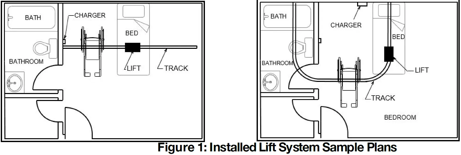
Overview of C-450/C-625 Lift SystemThe C-450/C-625 is a lifting aid used by health care professionals and caregivers in homes, institutions, and long-term care facilities to lift, position and transfer clients or a disabled family member.The C-450/C-625 is one part of a ceiling lift system that lifts an individual directly from above, making it possible to transfer and reposition mobility impaired individuals safely, with dignity, and in comfort while minimizing both strain and risk to the caregiver. The ceiling lift also does not take up valuable floor space as most traditional methods do.
The C-450/C-625 lift is one of the three major parts that make up a ceiling lift system:
Lift – Motorized unit that raises and lowers an individual directly from aboveTrack – Custom tailored and securely mounted to a ceiling structure, wall or floor provides the path for the lift to traverse Sling – Specially designed fabric accessory that attaches to the lift’s carry bar to hold and support an individual for positioning or transfer
Refer to any user guides supplied with the accessories and reference them while reviewing this lift guide.
C-450 and C-625 Ceiling LiftsThe C-450/C-625 is designed to raise and transfer an individual along a track from one surface to another surface. The lift remains on the lift track when in use or charging. With manual configurations, the caregiver can move the patient along the track with minimal push/pull force. Power traverse configurations include a secondary motor that moves the patient along the track system with no push/pull force. Lifting, lowering, and traverse functions are controlled by the hand controller attached to the lift.
Lift SystemThe following parts are included with your new C-450/C-625 lift system:
- Pneumatic hand control
- Charger to be connected to end-point or constant charge contacts
- Owner’s manual
Additional parts may include:
- Slings – If a sling has been supplied with the lift, refer to the instructions included with the sling.
- Accessories – If additional accessories such as a turntable or transition gate system have been supplied with the lift, refer to the instructions included with those items.
Charging the Lift
- Before initial use, the lift unit must be charged for 5 hours.
- Charge the batteries regularly. It is recommended that the lift be left on charge when not in operation to maximize the life cycle of the batteries.
- The lift may remain connected to the charger indefinitely since the charger has a built-in regulator to eliminate the danger of overcharging.
The ceiling lift charges in one of two options, depending on its configuration:
- End-Point Charging – The rail features a charging point at one end, and the lift must be moved to that point in order to charge.
- Constant Charging – Charging strips run along the inside of the rail. The lift charges automatically, at any place on the rail. When the lift is charging, the lift indicator lights solid orange. When charging is complete, the lift indicator turns green. Constant charging can be equipped to all C-450/C-625 lifts except those with Return-To-Charge enabled.
Low BatteryIf the batteries of the lift are low and require charging, the indicator located on the underside of the lift lights orange, an audible alarm sounds every 10 seconds when button is pressed, and the LCD displays Low Batt!. Complete the transfer if one is in progress and immediately set the lift to charge.The lift may be used after one hour of charging from low battery. It is recommended to charge the lift a minimum of 5 hours to achieve maximum battery capacity.
If the batteries are fully discharged, the indicator on the lift control panel lights red an audible alarm will sound every 10 seconds when button is pressed, and the LCD displays Low Batt! on first line and UP: INHIBITED! on the second line.
- When the battery is discharged, the up function is disabled. Down, emergency down, and X-Y Traversing will continue to operate.
- Only use the charger that was supplied with the lift. Use of any other charger will void all warranties and may cause damage to the lift.
- Do not position the lift where it is difficult to disconnect the charger in an emergency.
- The unit can be isolated electrically from mains by unplugging the charger.
Plug TypesPlug types vary by geographical location. Refer to local electrical guidelines on the type of plug or voltage which can be used. Connection to the charger is an IEC 60320-C7 plug.
C-Series lifts are not compatible with any tracks with track lip separation less than 13.5mm.
Attach the Hand Controller to the LiftA sturdy ladder may be required to access the underside of the lift to re-attach the hand controller to the lift. Use caution whenever using a ladder.
Should the hand controller disconnect from the underside of the lift, it must be re-connected for proper operation.The hand controller of the C-450/C-625 is designed with metal ribbed pins to withstand normal usage. However, the connector can become disconnected if:
- The lift is pulled along the track by the hand controller cord.
- The hand controller cord gets wrapped around an object while a lift or transfer is being performed.
- Hand controller cord is accidentally pulled down by the caregiver or the individual being lifted.
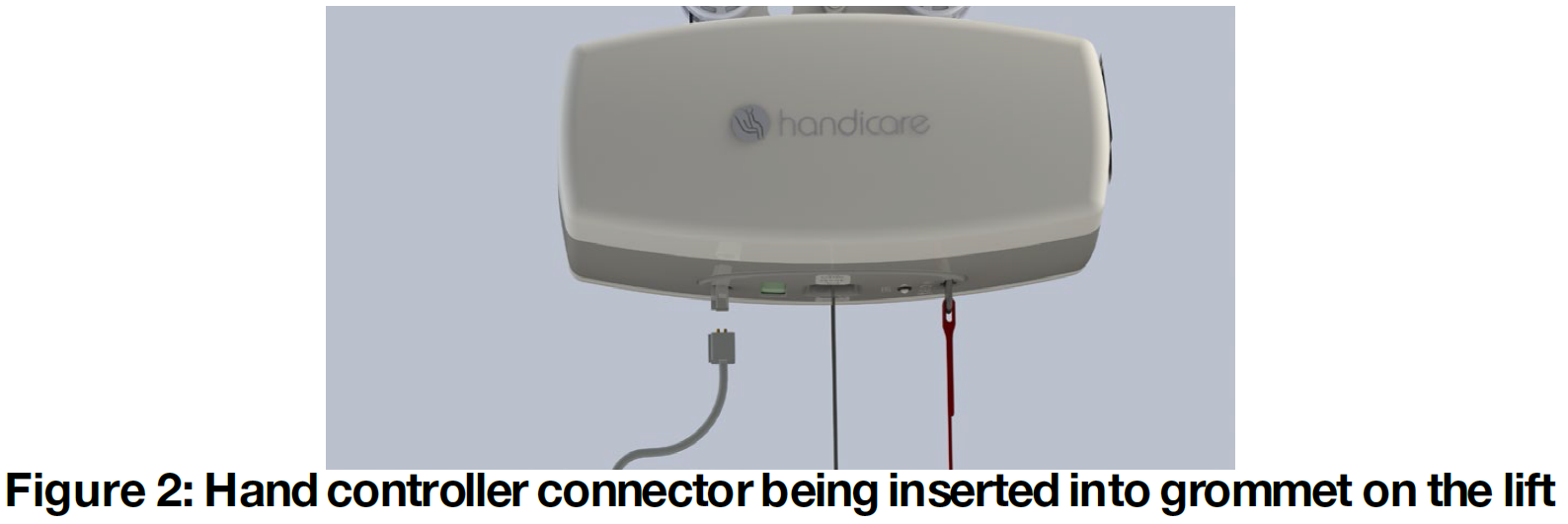
Connect the Hand ControlMake sure that the male connector is inserted into the lift connector in the proper orientation.
- Line up the small metal ribbed pins and the grey rubber groomet located on the underside of the lift as shown in Figure 2.The hand controller and groomet have a grey rib to be aligned to insure proper oreintation.
- Insert the cord connector completely into the connector on underside of the lift sufficiently so that it is secure.
- Pull lightly downwards on the connector to confirm proper connection.
Test the Hand ControlPerform a brief test to ensure proper connectivity:
- Turn on the lift as shown in the section titled “Turn On the Lift”
- Press any button on the hand controller. The LCD screen lights up on the lift.
- Raise and lower the carry bar using the Up button and Down button .
- If the carry bar moves up and down, the hand controller is properly connected, otherwise check:
- That the lift is on
- That the hand controller connector is properly connected
- That the LCD does not display Down Lim_Sw!
Change the Hand Controller HookIf an older style C450/C625 carry bar (360760) is to be equipped, it is recommended to install a C-Series hand controller hook (635603) on the hand controller for a more secure fit.
Turn On the LiftBefore using the C-450/C-625 lift system, check the lift, track, and sling for any unusual wear or damage. Refer to the owner’s manual for each piece of additional equipment to determine what should be checked. If anything looks unusual, contact your local Handicare dealer or your local Handicare business development manager before use. Failure to check the lift could result in damage to the lift or serious injury to the operator or the individual being lifted.
Press any button on the hand controller to turn the lift on. The indicator on the underside of the lift lights green and the LCD display screen on lift will turn on.
- If the batteries require charging, the lift indicator lights orange, an audible alarm will sound every 10 seconds when the button is pressed, and the LCD displays Low Batt!.
- If the batteries are discharged below 25% of capacity, the LCD displays Low Batt! and the lift will not raise, but will lower and the emergency lowering will function.
Turn Off the LiftThe lift automatically shuts off after approximately 5 seconds of non-use.In an emergency, the lift can also be shut off by pulling the emergency down strap. See “Emergency Stop” section for details on emergency stop and restarting the lift after an emergency stop.
Hand Controller OperationThe C-450/C-625 hand control operates the lift motion.
Figure 3 shows the hand controls for Manual Traverse, Power Traverse, and Power Traverse XY lift systems
Raise or Lower the Carry Bar
- Hold the hand controller in one hand.
- Hold the carry bar in the other hand so that it will not accidentally sway knock into an individual or nearby object.
- To raise the carry bar, press the Up button.
- To lower the carry bar, press the Down button.
Move the Lift on the TrackThe lift is moved along the track by either manual push/pull force, or by assist of a power traverse motor, depending on unit configuration.
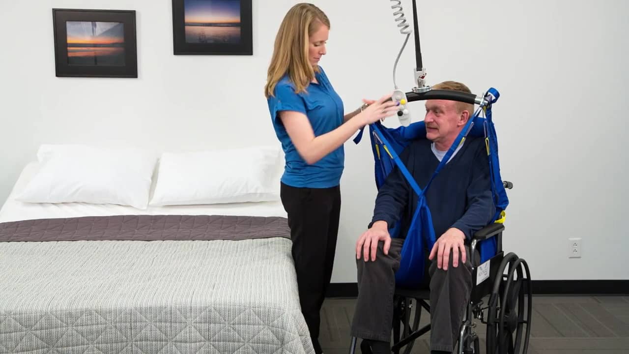
Transfer an Individual
The following steps are intended to generally illustrate the procedure of using the lift to transfer an individual from one location to another.Configurations vary by installation. Prior to attempting these steps, review the instructions for the sling and additional accessories you are using with the lift.
- Complete the “Each Use” inspection found in the “General Inspection and Preventive Maintenance” instructions.
- Move the lift close to the individual to be transferred.
- Follow the procedures for up and down and moving along the track as described in “Raise or Lower the Carry Bar” and “Move the Lift on the Track” sections.Avoid any obstructions that may cause injury to the individual in the sling or damage to the lift.
- Prepare the individual being transferred with the appropriate sling.
- Prior to lifting, make sure that the sling is correctly fitted and adjusted around of the individual for maximum comfort and safety.
- Position the lift directly over the individual.
- Lower the carry bar.
- Always check to ensure that the lift is correctly positioned directly above the person to be lifted. The lift straps may fray over time if repeatedly positioned improperly.
- Ensure that the carry bar has no cuts, dents, or sharp edges that may come in contact with the straps of the sling and cause damage to them. Report any concerns to your Handicare dealer or your local Handicare business development manager.
- Attach the sling loops to the carry bar.
- The straps on each side of the sling are generally attached to the corresponding side of the carry bar.
- Double-check to ensure that:
- The straps are properly attached to the carry bar.
- The individual being lifted is properly positioned in the sling prior to lifting.
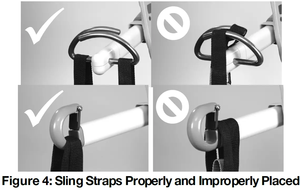
- Prior to lifting an individual, ensure the hand controller cord is free of the carry bar.
- Prior to lifting an individual, make sure that the straps of the sling are securely placed on the hooks of the carry bar and that the straps will not come off. (Figure 4).

- On the hand controller, press the Up button . The lift raises the individual.
- Make sure the individual is lifted to an appropriate height for a safe transfer that avoids any obstructions that may cause injury to the individual in the sling or damage to the lift.
- Move the individual along the track to the desired location.If using a manual traversing lift:
- Lower the carry bar to a comfortable height so that it can be easily handled.
- Grab hold of the carry bar and move the lift along the track by gently pushing the carry bar or the individual in the sling.If using a power traversing lift:
- Use the blue and yellow directional hand controller buttons to move the lift.
- The blue and yellow buttons correspond to the blue and yellow directional arrows on the underside of the lift; simply press the button matching the one on the lift for the direction you want it to move.
- When the individual is at the desired location, press the Down button to lower the individual to the correct height.
- Before you remove the sling loops from the carry bar, check that the transferred individual is securely supported in the appropriate position.
- Press the Down button to lower the carry bar so the sling straps can be easily removed from the carry bar
- Remove the sling straps from the carry bar.
- Press the Up button to raise the carry bar to a safe height.
- Use the blue and yellow directional buttons to move the lift out of the way, if equipped (i.e., away from the immediate area).
- Remove the sling from the individual.
- Store the sling in a safe place.
- Press the Up button to raise the carry bar to height where it is out of the way while not in use.
- Charge the lift as described in “Charging the Lift.”
WARNING: STRANGULATION HAZARD
- Following the completion of the transfer, ensure that the carry bar, strap, and hand control are raised up away from reach of children, toddlers, or anyone not intended to use the product.
- Psychological, mental, and emotional state assessment is key to safe use of a ceiling lift; ensure that use and storage of the ceiling lift and accessories are safe for the patient’s mental condition.
- While raising a ceiling lift system with or without patient, ensure that the patient, caregiver, other individuals, furniture, and other items are not at risk of becoming entangled with the moving lift strap and carry bar.
Traversing Beam TransferIf the ceiling lift is being used in an X-Y system with a traversing beam, be sure to understand the traversing beam and how it works in transferring an individual. As shown in Figure 5, the X-Y system features two parallel support tracks with one traversing beam mounted across.
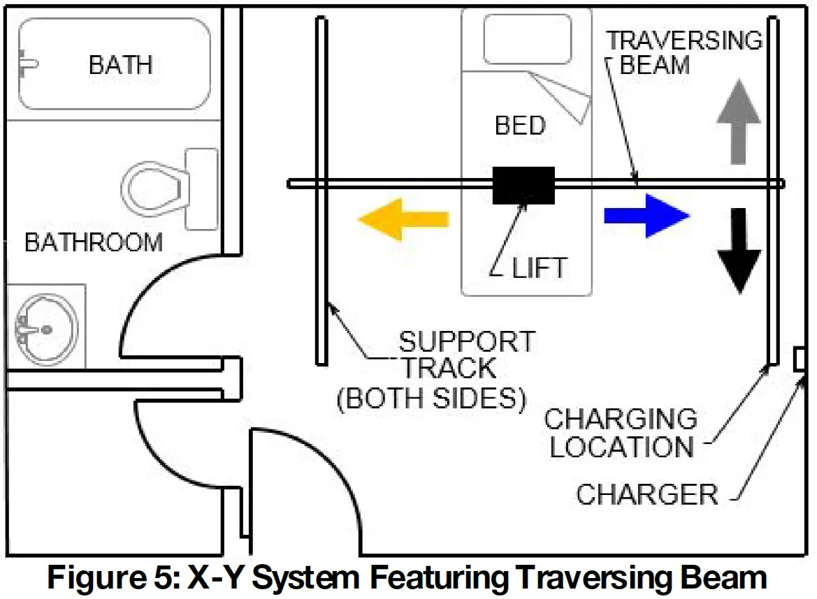
The lift can be moved along the traversing beam, and the traversing beam itself can be moved along the two parallel support tracks. Because of this, an X-Y system provides complete coverage over the area is between the support tracks.
If using a manual traversing beam:
- Move the beam along the support tracks manually to transport the beam, lift, and individual together.
- Lower the carry bar to a comfortable height so that it can be easily handled.
- Grab hold of the carry bar and move the lift and traversing beam along the track by gently pushing the carry bar or the individual in the sling.
If using a power traversing beam:
- Move the beam along the support tracks by pressing either the black button or white button on the hand controller to transport the beam, lift, and individual together.
- Use the black and white directional hand controller buttons ( and ) to move the traversing beam.
- The black and white buttons correspond to the black and white directional arrows on the underside of the power traverse X-Y system lift; simply press the button matching the one on the lift for the direction you want it to move.
- Use the blue and yellow directional hand controller buttons ( and ) to move the lift along the traversing beam.
- The blue and yellow buttons correspond to the blue and yellow directional arrows on the underside of the traversing lift; simply press the button matching the one on the lift for the direction you want it to move.
When moving the traversing beam, avoid any obstructions that may cause injury to the individual in the sling or damage to the lift or track.
LCD Information and Diagnostics
Display ModesThe lift unit can be set to the following display modes:
- Battery Level (default)
- Number of Lifts
To change from one operating mode to another please call your local service technician.
Battery Level
- Displays “Battery” with the percentage charged (in 5% increments) in the top row of the display (e.g., “Battery 65%”).
- Displays a bar graph of the battery level in the second row of the display by displaying the appropriate number of fully blackened rectangles as in the following diagram:
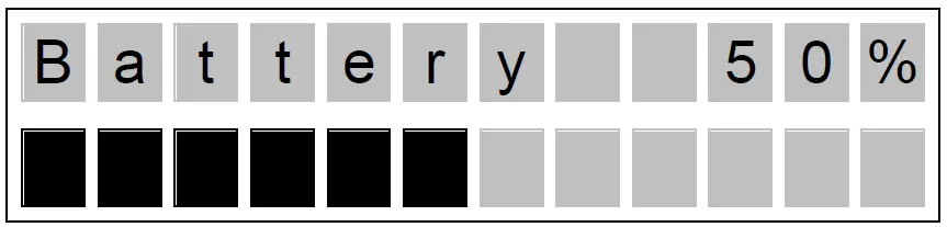
Note: As the lift is initially switched on, the level of battery charge displayed may be incorrect. However, as soon as the lift is operated, the charge level will update to the correct level.
Number of LiftsDisplays “Lifts” with the number of lifts completed in the top row of the display (e.g., “Lifts 500”) and a bar graph to indicate the battery level:

Low Battery ModeIn either display mode, when the battery level falls below 25%, the lift will go into Low Battery Mode. The lift will:
- Change the indicator light on the lift to ORANGE.
- Make an audible beep every ten (10) seconds.
- Display will show the battery % in the first line and the charge level bars in the second line.
If the batteries are fully depleted, the lift will:
- Change the indicator light on the lift to RED.
- Make an audible beep every ten (10) seconds.
- Display will show “Low Batt!”
Charging Display ModeIf the unit is charging, the lift will go into Charging Display Mode, regardless of the default display mode. Charging Display Mode will override Low Battery Mode.The lift will display “Charger” with the percentage charged (in 5% increments) in the top row of the display (e.g., “Charger 65%”).
Preventative Maintenance
The lift will recommend preventative maintenance if it hasn’t had service for 1000 lifts or 5 total working hours of operation, whichever occurs first.When the lift alerts you that PM is recommended, the lift will:
- Beep every 5 seconds
- The display will alternate between “Maintenance” and the default display mode.

If battery is below 25%:
- The indicator light goes to ORANGE
- Beep every 5 seconds
- The display alternates between “Maintenance” and the default display mode
If battery is depleted:
- The display will FLASH “Low Battery” on the first line
- The indicator light will go to RED and the beeping will stop
When the lift alerts you that PM is recommended, complete the “Semi-Annually” PM procedure and reset the lift counter.
Preventative Maintenance Counter Reset
- The lift must be in power off state.
- Press and hold both Up and Down buttons on hand control. The display will indicate “Tech-Prog” and unit will beep.
- Release both buttons and press the UP button until “Done” appears in the LED display with a beep.
- PM Lifts counter will be “zero” (0).
- Use lift as normal.
Emergency Stop and Lowering
Emergency StopThe lift unit has an emergency shut-off feature, such that in an emergency, power to the lift can be completely shut off.To perform an emergency stop, pull down once on the red emergency lowering cord on the underside of the lift unit so that the emergency switch clicks into the OFF position. In this state, the lift will immediately stop, beep once, the indicator and display will shut off, and all unit output will be disabled.If the emergency stop is activated for any reason, it is recommended to perform a complete inspection prior to returning to service. To restore function to the lift, press the white tab at the top of the red emergency lowering cord back into place.
Powered Emergency LoweringIn the event that the down function on the hand control does not function and the patient can not be lowered by normal means, check that the hand control connection is secure and that the emergency stop has not been activated.If the down function continues to not operate, the ceiling lift can be lowered by powered emergency lowering, overriding control functions. To activate, pull and hold down the red emergency lowering cord to the fully extended position. The lift strap will lower and a continuous alarm will sound as long as the cord is being pulled. Emergency lowering will stop, and the switch will return to the emergency stop position when the cord is released. Only lower the strap by emergency lowering to a point where the patient can be safely transferred from the ceiling lift.
Use of the powered emergency lowering after the patient has been lowered to a safe surface may damage the equipment. Misuse of emergency lowering is not covered under warranty.Following an event where emergency lowering is required, the lift must be inspected and repaired by a qualified technician.
Manual Emergency LoweringIn the event that both the hand control and powered emergency lowering does not function, the patient can be lowered by manually turning the motor.
- Manual emergency lowering is to only be used if the lowering procedures described previously do not function.
- A proper safety ladder or stool may be required in order to remove the cover of the device.
- DO NOT attempt to use the lift’s functions while using manual lowering.
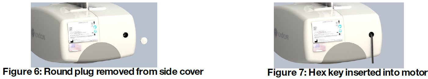
To perform Emergency Manual Lowering:
- Locate a 4 mm hex key
- One is supplied with each unit, packaged with the owner’s manual
- Locate and remove the small round clip on the side of the lift (figure 6).
- Insert the hex key into the end of the motor driveshaft, exposed through the window (figure 7).
- Turn the hex key clockwise to lower the lift strap.
Following an event where emergency lowering is required, the lift must be inspected and repaired by a qualified technician.
Cleaning and Disinfection
Cleaning the Lift and Carry BarThe exterior of the lift should only be cleaned and disinfected with isopropyl alcohol. Dampen a cloth with isopropyl alcohol and wipe down the entire exterior of the lift and carry bar.
Ensure that no liquids get inside the lift unit. Failure to protect the lift from liquids may result in damage to the lift and result in personal injury.
Cleaning the Lift StrapThe lift strap has been tested to be compatible with Virox Accel TB RTU (Ready-to-Use). Consult your local Handicare representative for guidance on other disinfectancts.
Do NOT use products containing chlorine, as this will degrade the strap material.
Optional Features
Quick Release HookAttach the QRS Carry Bar to the Quick Release Hook
- Hold down the red latch and align the Quick Release Hook slot with the carry bar’s clevis pin (figure 8).
- Hook the Quick Release Hook onto the carry bar’s clevis pin (figure 9).
- Make sure the latch is closed completely once the clevis pin is seated in the Quick Release Hook.
If the latch does not close completely, DO NOT USE THE QUICK RELEASE HOOK. Contact your local Handicare dealer or your local Handicare business development manager for service.
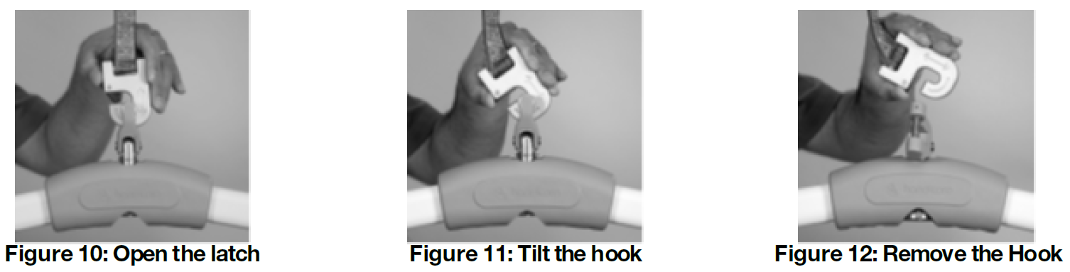
Detach the QRS Carry Bar from the Quick Release Hook
- Hold the hook and carry bar.
- Push the latch down to open it (figure 10).
- Hold the latch down and tilt the hook about 90° (figure 11).
- Remove the carry bar from the quick release hook (figure 12).
Return to Charge
If your power traversing lift has return-to-charge (RTC) equipped, press and hold the blue and yellow colored directional hand controller buttons simultaneously for 3-5 seconds until it beeps to activate. The lift automatically retracts the carry bar and drives along the track until it docks at the charger.
If the operator inadvertently enables return-to-charge while a patient is in the lift, the function stops automatically by sensing excess load on the lift. If the lift’s carry bar gets tangled with obstacles such as furniture or drapery during return-to-charge, the lift automatically detects the change in the load. If the load varies more than 15-30 lb (6.8-13.6 kg), the lift stops automatically. The overload threshold is between 35-50 lb (15.8-22.6 kg).
- The return-to-charge feature can be interrupted manually either by pressing any button on the hand controller or by grasping the carry bar firmly.
- The return-to-charge feature does not work with power traversing lifts equipped with constant charge (Omni).
- Make sure the carry bar is attached to the lift before activating return-to-charge. The added weight of the carry bar is required to ensure correct limit switch operation.
- Avoid any obstructions that may cause injury to the individual in the sling or damage to the lift or track.
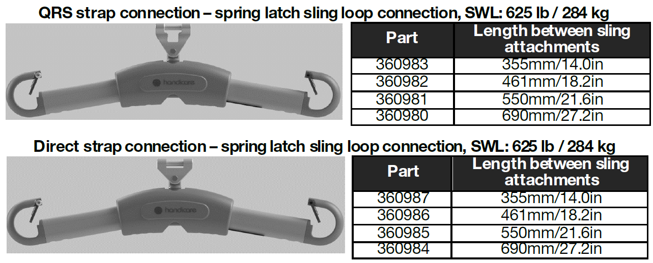
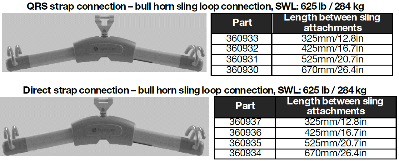
Carry Bars
Troubleshooting
Use the fault column to locate the symptom, then complete the recommended solution in the adjacent column on the row.If you cannot find the fault or the recommended solution does not correct the problem, contact your local Handicare authorized dealer for service.
| Fault | Recommended Solution |
| The airline tubing that connects the hand control to the lift has become disengaged. | Refer to “Attach the Hand Controller to the Lift.”If this does not correct the problem, contact your local authorized dealer immediately to check the lift and ensure proper continued operation. |
| The hand control buttons do not operate according to their designations (e.g. the UP button initiates a traverse movement). | Ensure that airline tubing is properly connected (see “Attach the Hand Controller to the Lift.”) Ensure the white plastic tab located at the end of the red emergency loweringcord is fully pressed into the lift unit.Ensure the lift is charged; refer “Charging the Lift.”If this does not correct the problem, contact your local authorized dealer immediately to check the lift and ensure proper continued operation. |
| The lift strap does not lift up or down even when the airline is properly connected and hand LCD is on. | The indicator light on the control panel located on the underside of the lift should be green. Press the On button or Up/Down arrow buttons or any colored button on the hand controller. This should activate the lift and the indicator light turn green.If the lift still does not function, the batteries may be low and require charging. Refer to “Charging the Lift” and charge the lift for at least one hour, then try to raise or lower the carry bar.If the emergency lowering has been used, the Up and Down functions will not operate. DO NOT use the lift. Contact your local authorized dealer immediately so that the lift can be checked to ensure proper continued operation. |
| The green light on the underside of the lift is On and LCD is On but the lift does not operate in the DOWN direction. | There is a built-in slack tape detector in the lift. This may be sensitive. Apply weight to the carry bar while pressing the Down button. If this corrects the problem temporarily but not permanently, contact your local authorized dealer immediately to check the lift and ensure proper continued operation. |
| The red indicator light on the underside lift turns red or a loud alarm sound is heard when an individual is raised. | The batteries are low and require charging. Refer to “Charging the Lift”. Charge the lift for at least one hour and then try to raise or lower the carry bar.If this does not correct the problem, contact your local authorized dealer immediately to check the lift and ensure proper continued operation. |
| One side of the lift strap is starting to fray after continued use. | Discontinue using immediately and replace strap. Check to be sure that the lift is always directly above the individual being lifted, especially with power traversing lifts. Refer to “Transfer an Individual” for correct lift positioning. If fraying still continues, contact your local authorized dealer immediately to check the lift and ensure proper continued operation. |
| The lift does not pass through a track component such as a turntable or transistion gate. | Refer to the owner’s manual for the specific piece of equipment in question. If the recommended solution does not correct the problem, contact your local authorized dealer immediately tocheck the lift and ensure proper continued operation. |
| No Power | Ensure the Emergency Lowering tab has not come out. If it has, simply press the tab back into the lift and check battery for charge. |
| Lift starts beeping while pulling Emergency Down Strap/Switch with strap not coming down. | The C-Series lift is equipped with dual sensors for strap tension and position. The Emergency Down Strap/Switch system only works with load on the strap and Emergency Down Strap/Switch motion stop immediately after the lift strap is loose. |
| Fault | Recommended Solution |
| Hand Control Button Functionality Reversed/Lift strap spooled in reverse direction/Pulling Emergency Down Strap/Switch moves lift strap “UP” | Press the “UP” on the hand control, strap should start movingout of the lift, continue pressing “UP” button until the strap fully unwinds and will start winding in the correct orientation. Now the “UP” button will move the strap in the up direction.If the lift is equipped with RTC feature, activate the RTC function by pressing and holding “Left and Right” buttons together. The strap will move in the downwards direction unit it reaches the lowest limit. Once it reaches its lowest limit, the strap will start moving up again in the correct orientation. |
| The lift is recommending preventive maintenance. | Complete the “Semi-Annually” maintenance procedure prior to resetting the lift counter. |
C-450/C-625 Lift Specifications
| Lift Motor: | 24 VDC |
| Traverse Motor: | 24 VDC (Optional at time of Purchase) |
| XY Traverse Motor: | 24 VDC (Optional at time of Purchase) |
| Charger: | Model: Soneil, 2403SRM20 |
| Input: 100-240 VAC 1.5 Amps, 50-60 Hz | |
| Output: 24 VDC, 1.0 Amps | |
| Note: Only use the Soneil, 2403SRM30 or Mascot 9940 chargers as alternates with the C-450/C- 625 Lift. Other chargers, including the A450/A625 charger, are not compatible to the C-450/C-625. | |
| Batteries: | 24 VDC (2 x 12 VDC) 5.0 AH, Sealed Lead Acid |
| Lift Case: | Flame Retardant ABS |
| Hand control: | Pneumatic |
| Main Unit IP Rating | IP22
IP22 = Protected against access tohazardous part by finger, protected against vertically falling water drops up to 15 degrees |
| Lifting Range: | Up to 96” (2438mm) |
| Lift Weight: | 21—23.5 lb (9.5-10.65 kg) |
| Maximum Safe Working Load: | 450 lb / 204.5 kg (C-450) or 625 lb / 284 kg (C-625).
Note: The maximum safe working load (SWL) of the installed lift is determined by referring to the product label located on the bottom of the lift. |
| Duty Cycle: | 1 Min On—9 Mins Off |
| Max Sound Level: | Raising Max load 56.1 dB, Lowering Max load 60.3 dB on a lift in good working order. |
| Service Life: | 22,500 cycles or 10 years, whichever comes earlier.
As a precautionary measure, the lifting strap should be replaced every 5000 cycles or 3 years, whichever comes earlier. Higher usage lifts may necessitate more frequent replacement of the lifting strap. See “General Inspection and Preventive Maintenance.” |
| Usage Environmental Conditions: | Temperature: +5º to +40º C (41 to 104 °F) |
| Relative Humidity: 15 to 90% RH | |
| Atmospheric Pressure: 70 to 106 hPa | |
| Storage Environmental Conditions | Temperature: -40º to +70º C (-40 to 158 °F) |
| Relative Humidity: 10 to 100% RH | |
| Atmospheric Pressure: 500 to 1060 hPa | |
| Rated Performance: | 30-40 lifts at 625 lb (284 kg)
50-60 lifts at 450 lb (204.5 kg) 1 min “on”, 9 min “off” Each lift being 24” (610 mm) at the middle of the lifting range (from 54” (1370 mm) strap out to 30” (762 mm) strap out) per full battery) Note: The lift has a break in period; breaking in of the lift will need to be done before these numbers will be achieved. The breaking in period varies from lift to lift and depends on the frequency of use and the types of load being applied. Higher loads and a greater frequency of use break in the lift faster. |
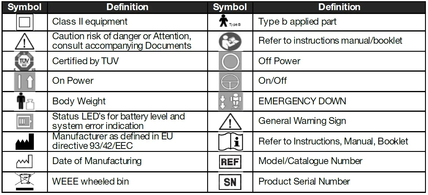
C-450/C-625 Lift Display Symbols
Warranty
This Warranty does not affect or in any way limit your Statutory Rights.Handicare guarantees all equipment, which includes Ceiling Lifts, Floor Lifts, Slings, Service Parts and Track and accessories, supplied as new, against failure within the period of 1 year from date of installation or 18 months from date of manufacturing, whichever is shorter, by virtue of defects in material or workmanship.Handicare guarantees all refurbished equipment supplied against failure within a period of three months from date of installation or six months from date of purchase whichever is shorter.This guarantee does not apply to failure attributable to normal wear and tear, damage by natural forces, user neglect or misuse or to deliberate destruction, or to batteries more than 90 days after original purchase.This guarantee shall be void if the equipment is not serviced by Handicare or its authorized service agents in accordance with the manufacturer’s recommendations or if any unauthorized person carries out works on the equipment.The liability of Handicare under the terms of this guarantee shall be limited to the replacement of defective parts and in no event shall Handicare incur liability for any consequential or unforeseeable losses.
Always make sure you have the correct version of the manual. The most recent version is available on our website, www.handicare.comFor questions about the manufacture or operation of this equipment, contact your local Handicare dealer or your local Handicare business development manager.
About HandicareHandicare offers solutions and support to increase the independence of the physically challenged or elderly people and to enable them to live an active life—on their terms—and to facilitate for their care providers and family. The offering encompasses a comprehensive range of curved and straight stairlifts, transfer, lifting and repositioning aids, vehicle adaptations and medical equipment. Handicare is a global company with sales in more than 20 countries and is a market leader in this field. The head office is in Stockholm, Sweden and manufacturing is located at six sites distributed across North America, Asia and Europe.
![]()
References
[xyz-ips snippet=”download-snippet”]