HH ELECTRONICS Tensor-Go Portable Battery Powered Array User Manual
DESIGNED AND ENGINEERED IN THE UKWWW.HHELECTRONICS.COM
 Intended to alert the user to the presence of uninsulated ‘Dangerous Voltage’ within the products enclosure that may be sufficient to constitute a risk of electrical shock to persons.
![]() Intended to alert the user of the presence of important operating and maintenance (Servicing) instructions in the literature accompanying the product.
Intended to alert the user of the presence of important operating and maintenance (Servicing) instructions in the literature accompanying the product.
CAUTION:
Risk of electrical shock – DO NOT OPEN.
To reduce the risk of electrical shock, do not remove the cover. No user serviceable parts inside. Refer servicing to qualified personnel
WARNING:
To prevent electrical shock or fire hazard, do not expose this appliance to rain or moisture. Before using this appliance please read the operating instructions for further warnings.
EARTH or GROUND GREEN/YELLOW
NEUTRAL – BLUE
After unpacking your amplifier check that it is factory fitted with a three pin ‘grounded’ (or earthed) plug. Before plugging into the power supply ensure you are connecting to a grounded earth outlet.
If you should wish to change the factory fitted plug yourself, ensure that the wiring convention applicable to the country where the amplifier is to be used is strictly conformed to. As an example in the United Kingdom the cable colour code for connections are shown opposite.
GENERAL INSTRUCTIONS
In order to take full advantage of your new product and enjoy long and trouble-free performance, please read this owner’s manual carefully, and keep it in a safe place for future reference.
- Unpacking: On unpacking your product please check carefully for any signs of damage that may have occurred whilst in transit from the HH factory to your dealer. In the unlikelyevent that there has been damage, please re-pack your unit in its original carton and consult your dealer. We strongly advise you to keep your original transit carton, since in the unlikelyevent that your unit should develop a fault, you will be able to return it to you dealer for rectification securely packed.
- Amplifier Connection: In order to avoid damage, it is advisable to establish and follow a pattern for turning on and off your system. With all system parts connected, turn on source equipment, tape decks, cd players, mixers, effects processors etc, BEFORE turning on your amplifier. Many products have large transient surges at turn on and off which can cause damage to your speakers.By turning on your bass amplifier LAST and making sure its level control is set to a minimum, any transients from other equipment should not reach your loud speakers. Wait till all system parts have stabilised, usually a couple of seconds. Similarly when turning off your system always turn down the level controls on your bass amplifier and then turn off its power before turning off other equipment
- Cables: Never use shielded or microphone cable for any speaker connections as this will not be substantial enough to handle the amplifier load and could cause damage to your complete system.
- Servicing: The user should not attempt to service these products. Refer all servicing to qualified service personnel.
![]() FCC COMPLIANCY STATEMENTThis device complies with Part 15 of the FCC rules. Operation is subject to the following two conditions:
FCC COMPLIANCY STATEMENTThis device complies with Part 15 of the FCC rules. Operation is subject to the following two conditions:
- This device may not cause harmful interference
- This device must accept any interference received, that may cause undesired operation.
Warning: Changes or modification to the equipment not approved by HH can void the user’s authority to use the equipment.
Note: This equipment has been tested and found to comply with the limits for Class B digital device, pursuant to Part 15 of the FCC Rules. These limits are designed to provide reasonable protection against harmful interference in a residential installation.
This equipment generates, uses and can radiate radio frequency energy and if not installed and used in accordance with the instructions, may cause harmful interference to radio communications.
However, there is no guarantee that interference will not occur in a particular installation. If this equipment does cause harmful interference to radio or television reception, which can be determined by turning the equipment off and on, the user is encouraged to try and correct the interference by one or more of the following measures.
- Reorient or relocate the receiving antenna.
- Increase the separation between the equipment and receiver.
- Connect the equipment into an outlet on a circuit different from that to which the receiver is connected.
- Consult the dealer or an experienced radio/TV technician for help
CE Mark (93/68/EEC), Low Voltage 2014/35/EU, EMC (2014/30/EU), RoHS (2011/65/EU), RED (2014/30/EU), ErP 2009/125/EU
SIMPLIFIED EU DECLARATION OF CONFORMITY
Hereby, HH Electronics Ltd. declares that the radio equipment is in compliance with Directives 2014/53/EU, 2011/65/EU, 2009/125/EU
Full text of the EU declaration of conformity is available at the following internet address
support.hhelectronics.com/approvals
In order to reduce environmental damage, at the end of its useful life, this product must not be disposed of along with normal household waste to landfill sites. It must be taken to an approved recycling centre according to the recommendations of the WEEE (Waste Electrical and Electronic Equipment) directive applicable in your country.
The Bluetooth® word mark and logos are registered trademarks owned by the Bluetooth SIG, Inc. and any use of such marks by Headstock Distribution Ltd is under license. Other trademarks and trade names are those of their respective owners.HH is a registered trademark of Headstock Distribution Ltd.
INCORPORATED RADIO EQUIPMENT DEVICE TECHNICAL SPECIFICATION:
- Read these instructions.
- Keep these instructions safe.
- Heed all warnings.
- Follow all instructions.
- Do not use this apparatus near water.
- Clean only with a dry cloth.
- Do not block any of the ventilation openings. Install in accordance with manufacturer’s instructions.
- Do not install near any heat sources such as radiators, heat registers, stoves or other apparatus (including amplifiers) that produce heat.
- An apparatus with Class I construction shall be connected to a mains socket outlet with a protective connection. Do not defeat the safety purpose of the polarized or grounding-type plug. A polarized plug has two blades with one wider than the other. A grounding type plug has two blades and a third grounding prong. The wide blade or third prong is provided for your safety. If the provided plug does not fit into your outlet, consult an electrician for replacement of the obsolete outlet.

- Protect the power cord from being walked on or pinched, particularly at plugs, convenience receptacles, and the point they exit from the apparatus.
- Only use attachments/accessories provided by the manufacturer.
- Use only with a cart, stand, tripod, bracket, or table specified by the manufacturer, or sold with the apparatus. When a cart is used, use caution when moving the cart/apparatus combination to avoid injury from tip- over.
- The mains plug or appliance coupler is used as the disconnect device and shall remain readily operable. The user should allow easy access to any mains plug, mains coupler and mains switch used in conjunction with this unit thus making it readily operable. Unplug this apparatus during lightning storms or when unused for long periods of time.
- Refer all servicing to qualified service personnel. Servicing is required when the apparatus has been damaged in any way, such as when power-supply cord or plug is damaged, liquid has been spilled or objects have fallen into the apparatus, the apparatus has been exposed to rain or moisture, does not operate normally, or has been dropped.
- Never break off the ground pin. Connect only to a power supply of the type marked on the unit adjacent to the power supply cord.
- If this product is to be mounted in an equipment rack, rear support should be provided.
- Note for UK only: If the colours of the wires in the mains lead of this unit do not correspond with the terminals in your plug‚ proceed as follows:a) The wire that is coloured green and yellow must be connected to the terminal that is marked by the letter E‚ the earth symbol‚ coloured green or coloured green and yellow.b) The wire that is coloured blue must be connected to the terminal that is marked with the letter N or the colour black.c) The wire that is coloured brown must be connected to the terminal that is marked with the letter L or the colour red.
- This electrical apparatus should not be exposed to dripping or splashing and care should be taken not to place objects containing liquids, such as vases, upon the apparatus.
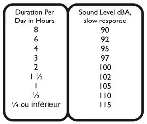
- Exposure to extremely high noise levels may cause a permanent hearing loss. Individuals vary considerably in susceptibility to noise-induced hearing loss, but nearly everyone will lose some hearing if exposed to sufficiently intense noise for a sufficient time.The U.S. Government’s Occupational Safety and Health Administration (OSHA) has specified the following permissible noise level exposures: According to OSHA, any exposure in excess of the above permissible limits could result in some hearing loss. Earplugs or protectors to the ear canals or over the ears must be worn when operating this amplification system in order to prevent a permanent hearing loss, if exposure is in excess of the limits as set forth above. To ensure against potentially dangerous exposure to high sound pressure levels, it is recommended that all persons exposed to equipment capable of producing high sound pressure levels such as this amplification system be protected by hearing protectors while this unit is in operation.
- Symbols & nomenclature used on the product and in the product manuals, intended to alert the operator to areas where extra caution may be necessary, are as follows:Intended to alert the user to the presence of high ‘Dangerous Voltage’ within the products enclosure that may be sufficient to constitute a risk of electrical shock to persons.Intended to alert the user of the presence of important operating and maintenance (Servicing) instructions in the literature accompanying the product.
Risk of electrical shock – DO NOT OPEN. To reduce the risk of electrical shock, do not remove the cover. No user serviceable parts inside. Refer servicing to qualified personnel.
 To prevent electrical shock or fire hazard, do not expose this appliance to rain or moisture. Before using this appliance please read the operating instructions.
![]() If your appliance features a tilting mechanism or a kickback style cabinet, please use this design feature with caution. Due to the ease with which the amplifier can be moved between straight and tilted back positions, only use the amplifier on a level, stable surface. DO NOT operate the amplifier on a desk, table, shelf or otherwise unsuitable non-stable platform.
If your appliance features a tilting mechanism or a kickback style cabinet, please use this design feature with caution. Due to the ease with which the amplifier can be moved between straight and tilted back positions, only use the amplifier on a level, stable surface. DO NOT operate the amplifier on a desk, table, shelf or otherwise unsuitable non-stable platform.

SETUP
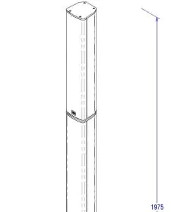
A. Tensor-GO Subwoofer and amplifierB. Two identical spacer pillarsC. Column Loudspeaker
Tensor-Go may be used with either one or two spacer units depending on the unit’s positionand your chosen usage. For floor mounted operation, two spacers are recommended.
Position the subwoofer on a stable surface in the desired location, then proceed to fit the spacer columns by firmly pressing into position. Finally insert the column loudspeaker, ensuringall joints are firmly pushed into position.
Care must be taken to position the unit to avoid causing a hazard, and ensuring it cannot beknocked over. If in doubt the unit should be secured in place.

Channel 1 & 2 are universal Mic/Line input channels that will accept a wide variety of sources.
- INPUT SOCKETS: Combi input sockets allow for the use of both XLR and 1/4″ Jacks, and accepts balanced and unbalanced signals. Note: a stereo signal on TRS lead cannot be connected directly.
- LEVEL: Use to set the channel level. Note, always set the Level to minimum before connecting an input and then slowly turning up to desired level.
- MIC/LINE SWITCH: This switch adjusts the channel gain structure to suit either microphones (or other low level devices) or higher line level devices. Always select this before adjusting the channel level.
- REVERB: This switch routes the channels signal to the internal reverb module.
Channel 3/4 is a stereo input channel for line level devices. All sockets may be used at the same time.
(5) AUX INPUTS: A 3.5mm stereo socket for connecting auxiliary audio from a source such as a mobile device.(6) RCA INPUTS: A pair of RCA phono sockets for connecting a line level source with RCA terminals(7) Bluetooth: Press to enable the integrated Bluetooth functionality. The LED will blink while in pairing mode. Look for ‘HH-Tensor’ on your device. Once connected the LED will stay on.Tensor-Go also supports TWS wireless stereo linking over Bluetooth with two Tensor-GO systems. TWS allows stereo audio to be routed from your mobile device to a pair of Tensor-Go systems providing rich true stereo sound. Connect your device to the first system as above, then press and hold the Bluetooth button for two seconds to enable TWS mode. On the second system, press and hold the Bluetooth button and the system will auto find and pair. Note, only Bluetooth audio is routed over TWS, not any hardwired inputs such as mics.
(8) LEVEL: Use to set the channel level. Note, always set the Level to minimum before connecting an input and then slowly turning up to desired level. For Bluetooth connections, adjust your devices volume to maximum for the best signal.
MASTER SECTION

(9) MASTER VOLUME: Controls the overall listening level of your Tensor-GO system. Note: Set this control to minimum when switching the unit ON or Off.(10) POWER: Illuminated green when the system is powered up.
(10) LIMIT: Tensor-GO is equipped with an onboard limiter to prevent overload to the power amplifiers and loudspeakers. The Limit LED will illuminate red when the Limiter is active. Occasional blinking of the Limit led is ok, but continuous illumination should be avoided by reducing the Master Volume slightly.(11) MODE: Four presets are included to optimise the response of the Tensor-GO to suit your needs. Cycle through them using the Mode button. Tensor-GO is equipped with an onboard limiter to prevent overload to the power amplifiers and loudspeakers. The Limit LED will illuminate red when the Limiter is active. Occasional blinking of the Limit led is ok, but continuous illumination should be avoided by reducing the Master Volume slightly.(11) MODE: Four presets are included to optimise the response of the Tensor-GO to suit your needs. Cycle through them using the Mode button.
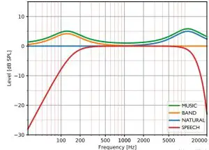
MUSIC: A Bass and Treble lift with flat midsBAND: A Bass lift with flat mids and highsNATURAL: A Treble lift with flat lows and midsSPEECH: A bass roll-off with flat mid and upper frequencies to ensure clarity on vocals.
(12) REVERB: Set the overall level of reverb with this control. Ensure you have routed a channel to the reverb with (4) first.(13) MIX OUT: A pre master volume signal feed which can be used to connect a second Tensor-GO, Stage monitor, house PA or recording console for example. The MIX OUT signal level is not affected by the VOLUME CONTROL.
14. MAINS INLET SOCKET: IEC input for connection of the included mains lead. Tensor-GO contains a universal mains input for worldwide usage without the need to change anything except your power cord.When powered, the internal lithium battery will be charged. The system can be operated normally whilst charging.
15. MAINS SWITCH: Turns the system on and off. It is good practice to turn the Master Volume control to minimum when switching on and off. The internal battery will charge even if the power switch is set to off.16. 12V DC IN: It is possible to charge your Tensor-GO from an external 12V power source such as a lead acid car battery or lithium-ion power pack.17. BATTERY STATUS: The charge LED will illuminate when charging. Battery charge status is indicated by the four LEDs, charge your Tensor-GO when the low level indicator is lit. For a reliable indication always check the status with the master volume turned down or any inputs muted.
SPECIFICATIONS:


For additional data, 2D and 3D drawings files, please check www.hhelectronics.com
- Measured in Full space (4π) conditions
- Calculated maximum SPL based on rated power handling
- AES standard, pink noise with 6 dB crest factor, free air.
report this adReferences
[xyz-ips snippet=”download-snippet”]