
HH TRE-1201 Active PA Speaker User Manual
INTRODUCTION
The HH Tensor engineered in the UK to deliver power, performance and reliability. The Class-D Bi-Amplifier delivers impressive output performance in an ultra-lightweight enclosure. On-board DSP provides audio enhancements depending on audio source and includes overload protection. Four acoustically tuned audio modes are provided for flexibility for use in a multitude of situations. Whether that’s for a DJ, live band, monitoring or announcements, the Tensor has it covered with the press of a button. High-quality integrated two channel mixer gives multiple options for input sources. Each input has HH designed lownoise preamps with combo XLR/TRS connectors for both Line Level and microphone gain levels. All this contained in a multi-angle enclosure that includes three moulded carry handles, pole mount socket and four M8 suspension points. The HH Tensor – delivering performance and reliability.
GETTING STARTED
This manual contains important information regarding correct and safe operation of your Tensor system. Please read it thoroughly in order to get the best performance and reliability from your HH product. Inspect the product during unpacking, If any damage is found notify the dealer you purchased it from immediately. Should you ever need to return the unit back to the dealer or HH Electronics ensure it is well packed and if possible use the original packaging.
POWER CYCLE
Many products have large transient surges at turn on and off which can cause damage to your speakers. Following the sequence below for power-up and the reverse for power down will prevent this from occurring.
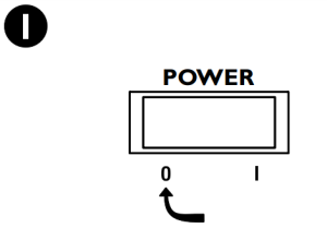
- POWER SWITCH – OFF

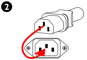
- CONNECT POWER
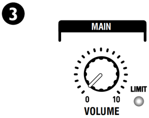
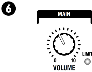
- SET VOLUME TO MINIMUM
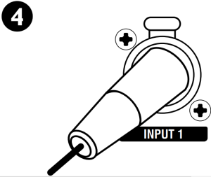
- CONNECT INPUT SIGNAL
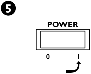
- POWER SWITCH – ON
- SET VOLUME AS REQUIRED
REAR PANEL CONTROL PANEL – THIS IS THE SAME FOR BOTH MODELS
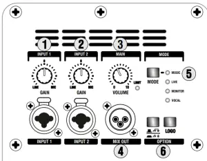
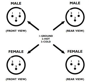
- INPUTS: A Combi Input allows for the use of both XLR and 1/4″ Jacks and accepts balanced and unbalanced signals.
- Note: a stereo signal on TRS lead cannot be connected directly, and must be split to two mono connectors.GAIN: Use to set the channel level.Note: Set the Gain control to minimum before connecting an audio signal.Once the system is powered up, we recommend that the Gain set to midway is a good starting point.
- MASTER VOLUME: Controls the overall level of your Tensor system.Note: Set this control to minimum when switching the unit ON or Off.LIMIT: The Tensor cabinets are equipped with an onboard limiter to prevent overload to the power amplifiers and loudspeakers. The Limit led will illuminate when the Limiter is active. Occasional blinking of the Limit led is ok, but continuous illumination could result in damage to the system and Main Volume should be reduced.
- MIX OUT: A signal feed which can be used to connect a second Tensor cab (daisy chained – see page 5), active wedge monitor, house PA or recording console for example. The MIX OUT signal level is not affected by the OLUME CONTROL.
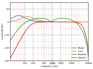
- EQUALISATION: Four presets are included to optimise the response of the cabinet to suit your needs. Cycle through them using the Mode button.MUSIC: A bass lift with a flat mid to high response.LIVE: Similar to the ‘MUSIC’ response with the LF lift frequency shifted.MONITOR: A LF and HF roll-off with a with a slight mid band cut for clarity.VOCAL: A bass roll-off with flat mid and upper frequencies.The EQ setting is stored and recalled following a power cycle. Please note the unit is shipped with the EQ mode set to “MUSIC.”
- OPTION: A Ground lift has been provided to reduce the potential problem of earth loops when connecting to other equipment. This control is to be used in conjunction with the MIX OUT.The Cabinets front logo illumination can be turned ON/Off with the Logo control.
REAR PANEL CONTINUED
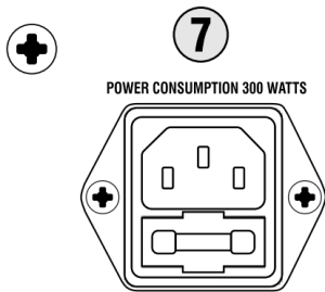
- MAINS INLET SOCKET AND FUSE: IEC input for connection of an appropriate mains lead. Only replace the fuse with the type indicated on the rear panel.
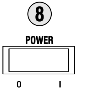
- MAINS SWITCH: Turns the system on and off. Ensure the Volume controls is set to minimum when switching on and off.
- VOLTAGE SELECT SWITCH: Although every effort has been made to select the correct voltage for the region of use. Please check the voltage setting is correct before powering up for the first time. Damage could occur if the voltage is incorrectly set. See below for more information.
- INFORMATION: Area relating to the amplifier: Serial Number, operational information, power rating, etc.CAUTION: TO REDUCE THE RISK OF FIRE REPLACE FUSE WITH SAME TYPE AND RATING.ATTENTION: POUR REDUIRE LE RISQUE DU FEU REMPLACEZ LE FUSIBLE PAR LE MEMES TYPE ET ESTIMATION. MADE IN CHINA. FABRIQUE EN CHINE.WARNING: THIS APPARATUS MUST BE EARTHED AVERTISSEMENT: CET APPAREIL DOIT ETRE MIS A LA TERRE WARNING: TO REDUCE THE RISK OF FIRE OR ELECTRIC SHOCK, DO NOT EXPOSE THIS APPLIANCE TO RAIN OR MOISTURE. DO NOT REMOVE COVER. NO,USER SERVICEABLE PARTS. REFER SERVICING TO QUALIFIED PERSONNEL.AVERTISSEMENT: POUR REDUIRE LE RISQUE DU FEU OU DE DECHARGE ELECTRIQUE. N’EXPOSEZ PAS CET APPAREIL k LA PLUIE OU AU MOISTURE. DO POUR NE PAS ENLEVER LA COUVERTURE. AUCUNES PIECES DE L’UTILISATEUR SERVICEABLE A L’INTERIEUR. REFEREZ-VOUS L’ENTRETIEN AU SERVICE QUALIFIE PERSONEL.
- AIR VENTS: These are critical for the longevity and reliability of the amplifier – DO NOT BLOCK. The same applies to the vents at the top of the control panel.


FUSE REPLACEMENT AND VOLTAGE SELECTION
SWITCH OFF AND DISCONNECT THE POWER CORD BEFORE PROCEEDING.
- POWER
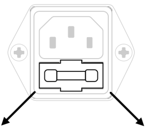
- FUSE REPLACEMENT
- Slide out the fuse holder tray.
- Only replace fuse with the same type and power rating as specified on the rear panel.
- VOLTAGE SELECTIONUsing a suitable tool, slide the voltage selector switch to the required operating voltage.
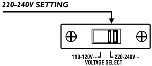
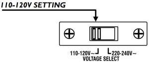 Using a suitable tool, slide the voltage selector switch to the required operating voltage.
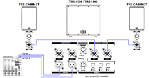
EXAMPLE 1 – Daisy chained
If additional cabinets are required in the signal chain, simply connect the Mix Out of the primary cabinet to the Input of the Secondary cabinet.
- PRIMARY CABINET
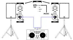
- EXAMPLE 2 – A DJ setup:
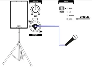
- EXAMPLE 3 – A mono microphone setup:
- EXAMPLE 4 – Stereo setup with mono bass:
- EXAMPLE 5 – Full stereo setup:


CONFIGURATIONS
The intuitive design of the Tensor cabinets provide user flexibility and a product that will serve in many situations:
A: Tripod/pole mounting – via the 35mm pole socket.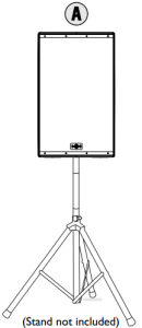
B: Pole on sub.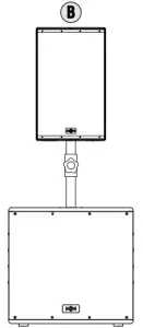
C: Flown vertically.
D: Flown horizontally.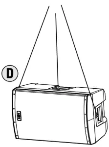
E: Freestanding – on the ground.
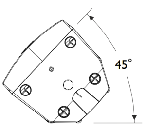
F: Monitor mode – the cabinets shape allows for horizontal/angled position on stage.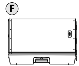
IMPORTANT
POLE MOUNT: Don’t over-extend poles/tripods; ensure at least 4 x the pole diameter is still inside the outer pole. Make sure the legs have a good splay on tripods, but do not obstruct doorways or other access-ways. Make sure that the thumb screw on the cabinet is tight.
SUSPENDED
WARNING: The suspension or ‘flying’ of cabinets should be performed only by properly qualified persons, in compliance with all local laws.
The position of installation is also bound by laws and regulations so must be taken into account in the initial planning stages. Hardware used must be fully approved for its intended use and be rated to support weights greater than that of the cabinet. All installation equipment used is subject to regular safety checks which must be strictly adhered to. If any of the hardware shows any signs of wear or damage, it should be replaced immediately. Failure to do so could result in serious injury or death!
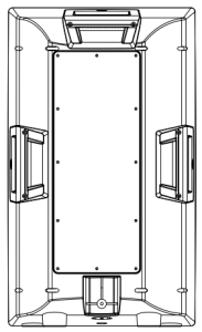
FITTING EYE BOLT
A: To fit the eye bolts, first locate and remove the four rubber protection caps (positions shown below).
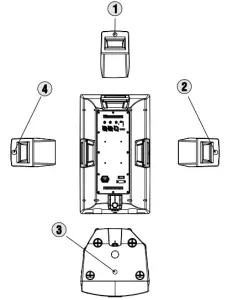
B: Replace with a suitable eye bolt. Ensure thread is fully engaged into the insert.Note that eye bolts for flying systems must be cast, shoulderedfittings rated for the purpose.Forged steel eye bolts of the type typically available from DIY suppliers are NOT suitable and should not be used under any circumstances.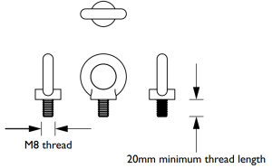
QUICK TIPS
- Use electronic safety devices such as circuit breakers.
- Master volume should be at zero for switch on and off.
- Use input gain to set maximum signal level without distortion.
- Set up microphone levels first, and adjust other equipment to match.
- Avoid very high onstage levels from back-line amps.
- Avoid damp environments and extremes of temperature for storage and use of all audio equipment.
- Look after your cables. Do not stand equipment on, or run cases over them, do not tie knots in them and always use them for the correct application (a signal lead is NOT a speaker lead). Coil and secure with cable ties before storing.
- Ensure your equipment is properly loaded and cannot move around during transit.
- Keep lights away from speakers; heat can cause fires/speaker damage.
- Don’t run cables across access-ways; if you have to, run them above doors or use approved cable covers.
- Be aware of total power usage. Overloading a mains socket is potentially dangerous, and likely to cause a power out during use.
- Keep power and signal cables apart.
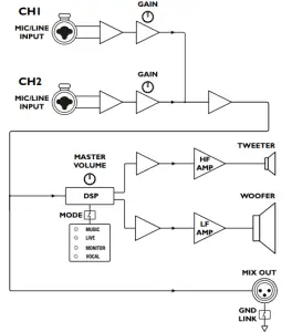
BLOCK DIAGRAM
1/O CONNECTOR WIRING

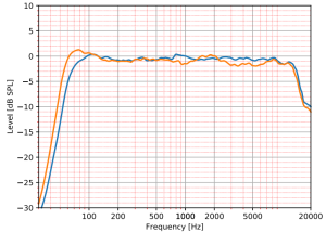
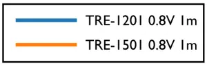
FREQUENCY RESPONSE
SPECIFICATIONS: TRE-1201
|
System type |
2way active 12″ loudspeaker, Bass reflex |
|
Power Rating |
1400WPeak, 700WContinuous |
|
Frequency response |
45Hz-20KHz |
|
Max SPL (1M) (Peak) |
130dB SPL |
| Speaker | |
|
LF Driver 12″ |
HH designed professional low mid driver featuring imported glass reinforced cone |
|
HF Driver |
1″ Compression Driver |
|
Coverage |
90°HX 60°V |
|
Crossover Frequency |
2.5KHz |
| Features | |
|
Input Connectors |
2x Balanced Combi XLR/1/4″ Jack connectors |
|
Output Connectors |
1x Balanced XLRMix Output |
|
Indicators |
Power, Clip Indicator, EQMode, Front illuminated logo |
|
EQ |
User selectable performance preset sfor Music, Live, Monitor, Voca |
|
DSP |
Crossover, EQ, Dual Band Limiters, Phase and Time Optimisation |
|
Protection |
Comprehensive protection and clip free limiting +clip indicator |
|
Controls |
2x channel gain, Master Volume, logo on/off, Ground Lift, EQMode |
|
AC Power |
User Switcheable 100-120or 220 240V~50/60HZ |
|
AC Power Consumption |
300WTypical |
| Enclosure | |
|
Cabinet |
Robust polypropylene cabinet with three handles andmonitor angle |
|
Finish |
Black |
|
Grille |
Heavy Gauge powder-coated steel, Black with acoustic foambacking |
|
Other |
35mmDistance Pole Socket |
|
Flying points |
4x M8Mounting Points |
|
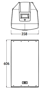
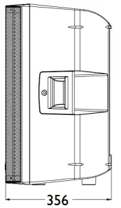
Unit dimensions(HWD) |
610x 357x 356mm24″ x 14.1″ x 14″ |
|
Unit weight |
14.4Kg, 31.7lbs |
|
Carton dimensions(HWD) |
685x 440x 440mm27″ x 17.3″ x 17.3″ |
|
Packed weight |
16.8Kg, 37lbs |
| Accessories | |
| SC-TRE12- Transport coverfor TRE-1201 |
In the interest of continued development, HH Electronics reserves the right to amend product specification without prior notification.
For polar plots, EASE modelling files, 2D and 3D drawings files, please check www.hhelectronics.com
- Measured in Full space (4π) conditions
- Calculated maximum SPL based on rated power handling
- AES standard, pink noise with 6 dB crest factor, free air.
SPECIFICATIONS: TRE-1501
|
System type |
2way active 15″ loudspeaker, Bass reflex |
|
Power Rating |
1400WPeak, 700WContinuous |
|
Frequency response |
41Hz-20kHz |
|
Max SPL (1M) (Peak) |
131dB SPL |
| Speaker | |
|
LF Driver |
15″ HH designed professional low mid driver featuring imported glass reinforced cone |
|
HF Driver |
1″ Compression Driver |
|
Coverage |
90°HX 60°V |
|
Crossover Frequency |
2.5kHz |
| Features | |
|
Input Connectors |
2x Balanced Combi XLR/1/4″ Jack connectors |
|
Output Connectors |
1x Balanced XLRMix Output |
|
Indicators |
Power, Clip Indicator, EQMode, Front illuminated logo |
|
EQ |
User selectable performance presets for Music, Live, Monitor, Vocal |
|
DSP |
Crossover, EQ, Dual Band Limiters, Phase and Time Optimisation |
|
Protection |
Comprehensive protection and clip free limiting +clip indicator |
|
Controls |
2x channel gain, Master Volume, logo on/off, Ground Lift, EQMode |
|
AC Power |
User Switcheable 100-120or 220 240V~50/60HZ |
|
AC Power Consumption |
300WTypical |
| Enclosure | |
|
Cabinet |
Robust polypropylene cabinet with three handles andmonitor angle |
|
Finish |
Black |
|
Grille |
Heavy Gauge powder-coated steel, Black with acoustic foam backing |
|
Other |
35mmDistance Pole Socket |
|
Flying points |
4x M8Mounting Points |
|
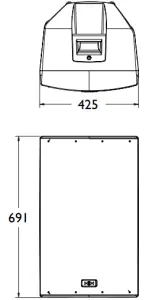
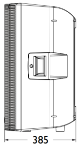
Unit dimensions(HWD) |
694x 420x 385mm27.3″ x 16.5″ x 15.2″ |
|
Unit weight |
18Kg, 39.7lbs |
|
Carton dimensions(HWD) |
775x 500x 465mm30.5″ x 19.7″ x 18.3″ |
|
Packed weight |
21.4Kg, 47.2lbs |
| Accessories | |
| SC-TRE15- Transport cover for TRE-1501 |
In the interest of continued development, HH Electronics reserves the right to amend product specification without prior notification.
For polar plots, EASE modelling files, 2D and 3D drawings files, please check www.hhelectronics.com
- Measured in Full space (4π) conditions
- Calculated maximum SPL based on rated power handling
- AES standard, pink noise with 6 dB crest factor, free air.

References
[xyz-ips snippet=”download-snippet”]