HiBOOST 4K/10K/15K Smart Link User Manual
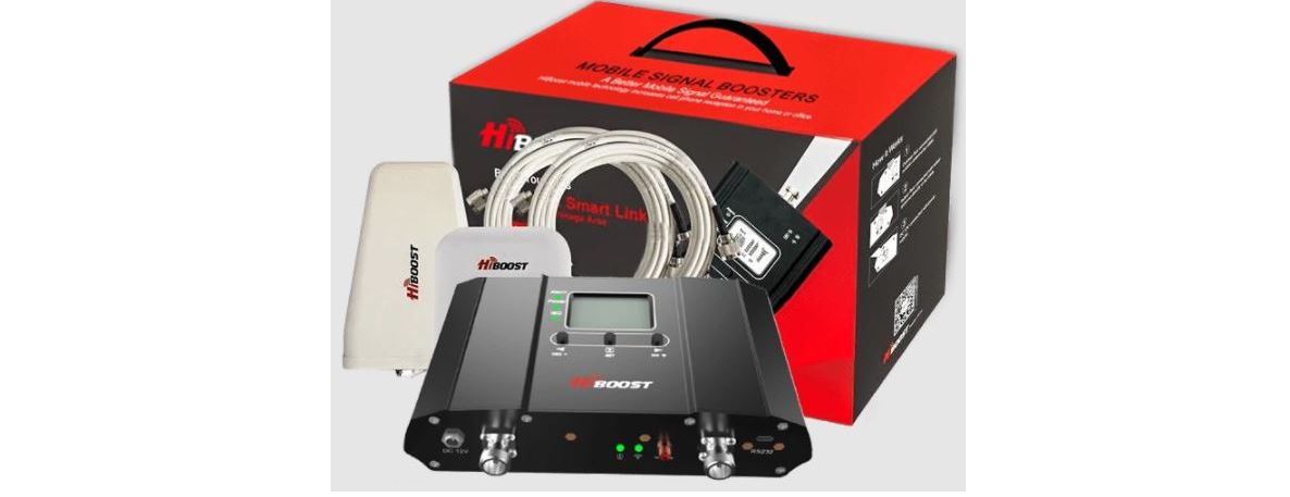
Package Content
NOTE: Available accessories can be purchased through HiBoost.comWarning: Un-authorized antennas, cables, and/or coupling devices are prohibited by new FCC rules. Please contact FCC for details: 1 (888)-CALL-FCC
Introduction
Thanks again for purchasing HiBoost’s Smart Link Signal Booster. The Smart Link Series is a collection of precision-engineered products that improve cellular reception inside of homes and businesses by amplifying incoming and outgoing cell phone signals.
HiBoost’s exclusive cloud-based Signal Supervisor mobile application and LCD display allow users to monitor the live status of HiBoost cell phone signal boosters directly from the LCD display or remotely from a mobile device anywhere at any time.
If there are any issues while installing a HiBoost cell phone signal booster, please contact the HiBoost technical support team through the following options:
24/7 Online Support: Create a ticket or chat via Signal Supervisor AppPhone: (972) 870-5666 (M-F from 9 am – 5 pm)Email: [email protected]Website: www.hiboost.com
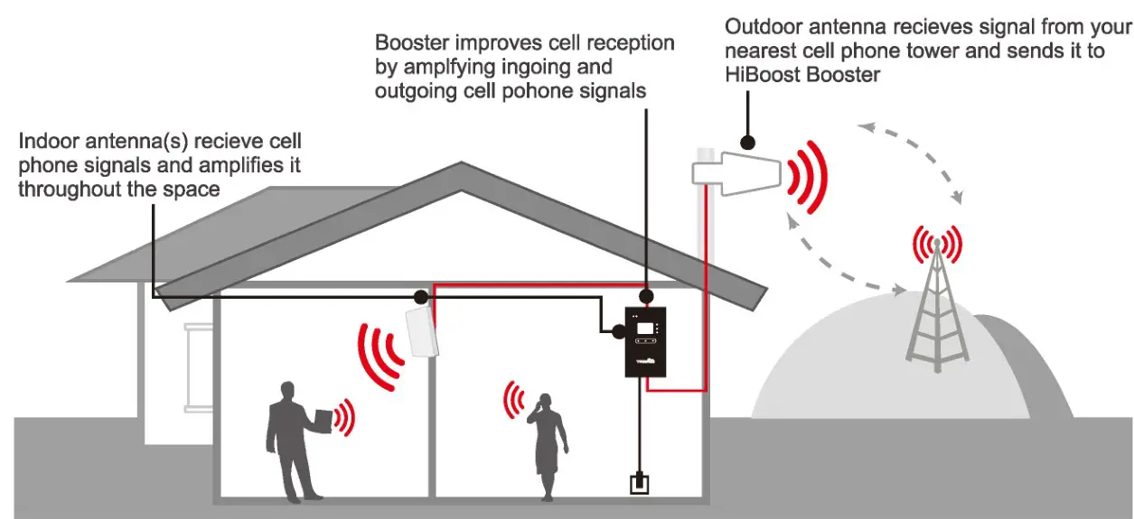
How HiBoost Signal Boosters Work
Pre-Installation Instructions
HiBoost’s Smart Link booster unit and antennas must be strategically placed in order to perform and provide maximum coverage.
The HiBoost Signal Supervisor app will allow users to communicate to the Smart Link signal booster via Wi-Fi. It will also allow users to communicate with your booster locally via Bluetooth connection. Once registered, the user can install, optimize and remotely monitor the Smart Link booster. If there is no Wi-Fi or Bluetooth connection, please reference the LCD installation method.
Note: Signal Supervisor enabled boosters must have access to a strong Wi-Fi network – If Wi-Fi is not available, users can connect to the booster with Bluetooth.
Professional Installation Tips:
- For a fast and optimize installation, it is strongly recommended that users install HiBoost products using the Signal Supervisor mobile application.
- Completely read the user manual and gather all necessary tools, material and accessories before installing the booster
- A “soft installation” is recommended before permanently mounting any equipment – this technique will simplify the installation process by allowing users to identify any potential installation issues beforehand
- The Signal Supervisor App integrates a tool that will help users locate the best location for the outdoor antenna – ensure that there is at least 20 ft of vertical separation between both antennas
Signal Supervisor App Setup
Before installing the Signal Supervisor App, please have the booster unit that is powered on and nearby.
Note: Turn on the Bluetooth feature enabled before attempting to register the booster to the mobile device.
Step 1: Download the Signal Supervisor App• The application is available for download through Apple’s App Store or
Step 2: Create a New Account and Log-in• Launch the app on your mobile device• Select the HiBoost Server• Log-in with an existing account or create a new one Google Play
Step 3: Register the Booster by adding a device on the home menu Go to My Devices > Add a Device > Wi-Fi Network
If you do not have Wi-Fi, continue with the No Wi-Fi Network option to connect via Bluetooth.
Note: Connecting to a Wi-Fi network is recommended for this installation because Bluetooth is limited to a range of only 30 feet
Installation – Signal Supervisor Method
Log into the Signal Supervisor app and power on your booster before beginning the installation process.The “Quick installation Guide” can be found on the app and it will help guide users through a fast and optimize installation.Access the Quick Installation Guide after registering the booster or go to:
My Devices > Select the Booster > Device Details > Quick Install Guide Follow the step-by-step instructions while installing and optimizing the booster system.
Note: Please remember that if the booster is connected via Bluetooth, then users are limited to a connection within a 30 feet radius from the boosterIf there are any issues while installing a HiBoost cell phone signal booster, please contact the HiBoost technical support team through the following options:
24/7 Online Support: Create a ticket or chat via Signal Supervisor AppPhone: (972) 870-5666 (M-F from 9 am – 5 pm)Email: [email protected]Website: www.hiboost.com
Installation – LCD Display Method
These are instructions that will allow users to install a Smart Link cell phone booster using the LCD Display.
Before using this method, please take a moment to become familiar with the LCD display, LED status indicators and control buttons on the booster.
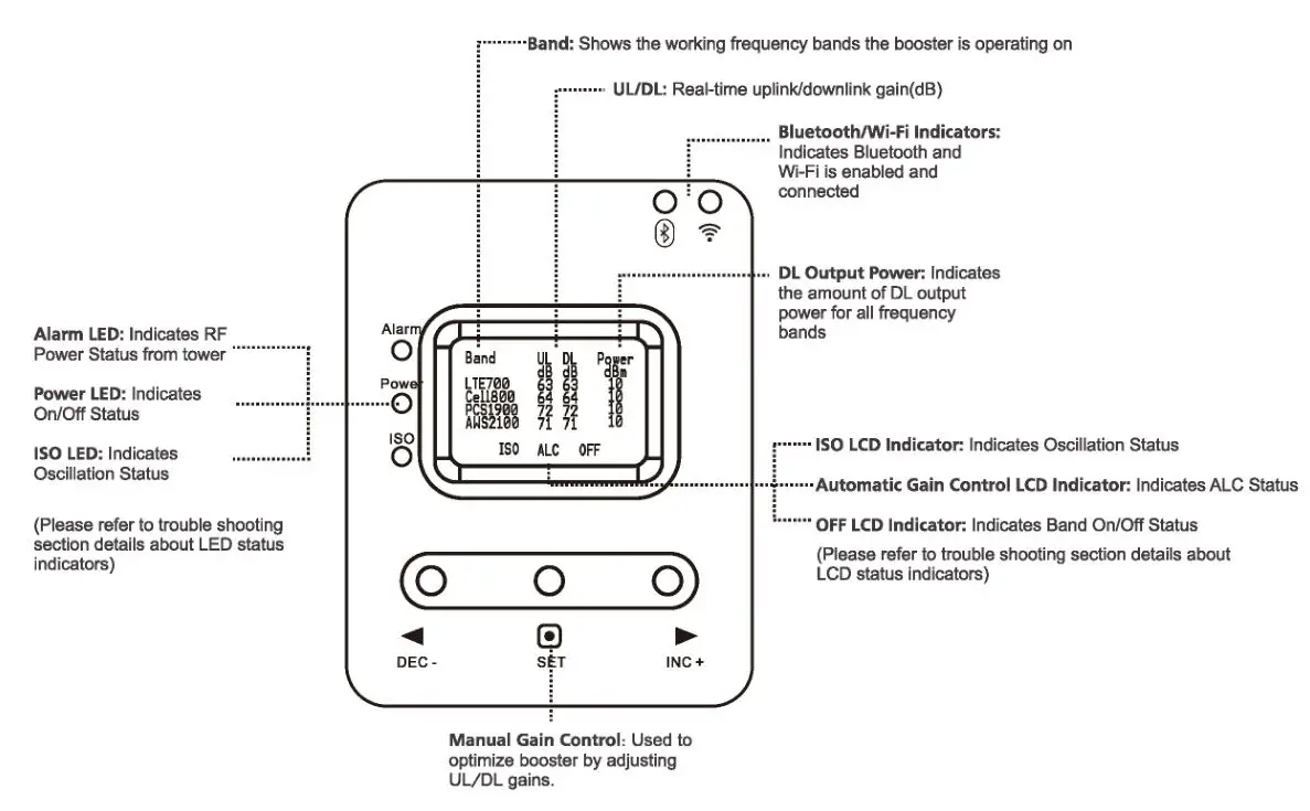
LED/LCD STATUS INDICATORS
Installation Overview
Before beginning the installation, it is important that users survey and plan the layout of the cell phone signal booster system. Please review the following instructions before attempting to install this system.
In this set up, the user will need to use the outdoor antenna to find the strongest source of nearby cellular signal (generally in the direction of the nearest cell phone tower). This will optimize the system by helping user install the booster and antennas in the best position and direction.
A. Finding the Strongest Outdoor SignalB. Install the AntennasC. Finalize the Installation
Part A) Finding the Strongest Outdoor Signal
The outdoor signal strength will affect performance. It is important that users install the outdoor antenna in the right position, pointing at the strongest source of signal or cell phone tower from the roof.It may help to narrow down the location of the nearest cell phone tower by visiting www.cellreception.com or www.antennasearch.com.Gaining height may also help if users are in rural areas where cellular signal is generally weaker. This installation may also require two people.
1. Connect the outdoor antenna to the booster using the coaxial cable included in the kit – push the cable firmly into the jack on both the antenna and the booster, then turn the connector sleeve clockwise until the connectors are tight
2. Place the booster in a location where it will be potentially installed and make sure that the booster is turned on3. Carry the outdoor antenna to the highest point on the roof to begin testingNote: Do not connect the indoor antenna to the booster while trying to find strongest source of outdoor signal
4. While pointing the antenna towards the horizon, slowly rotate around in a 360- degree circle and find the position that shows the highest maximum power output {dBm) and DL gain {dB) on the right-hand column on the LCD display
Note: Maximum power and downlink gain for the 4K SL is 1 OdBm/60dB, 1 OK SL is 12dBm/65dB, 1 SK SL is 12dBm/72dB
Professional Tips:
- Keep in mind that it is normal for the output values may vary dynamically between 1-3 dB
- To optimize the signal for one carrier, point the outdoor antenna towards the closest cell phone tower designated to that carrier
- To optimize the signal for more than one carrier, point the outdoor antenna between multiple towers
- Make sure to slowly turn the antenna while taking the readings so the booster has time to adjust the reading
- Test and install the antenna at the same height where power outputs and gain values reach the boosters maximum capacity
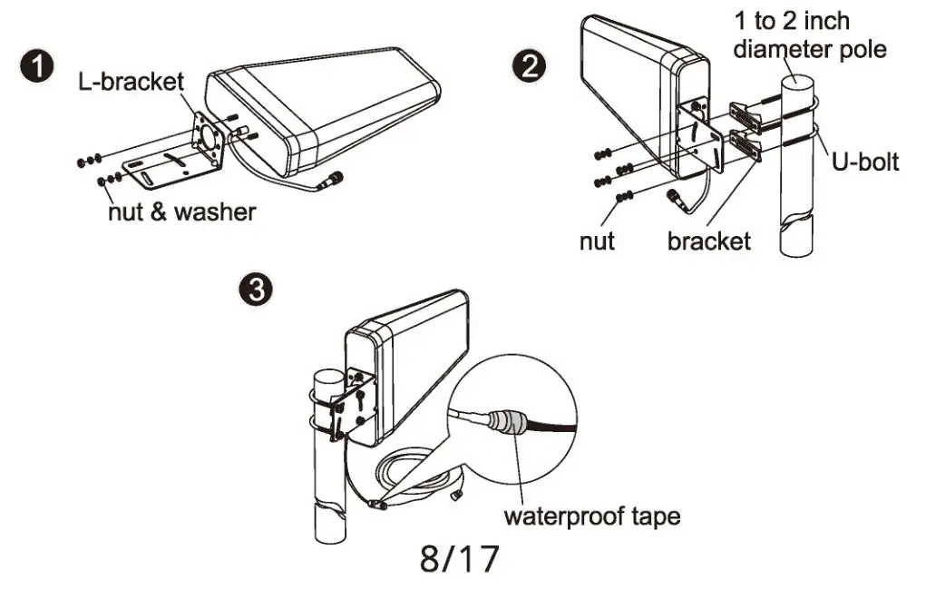
5. After narrowing down the best location for the outdoor antenna, finalize installation by using the hardware included in this kit and permanently mount it onto a mast
Note: Write down the maximum power output and downlink gain values – this will be important when installing the indoor antenna
Part B) Installing the indoor antenna(s)
While choosing a location for the indoor antenna, please keep in mind that there must be at least 20 ft of vertical separation between the outdoor and indoor antenna.
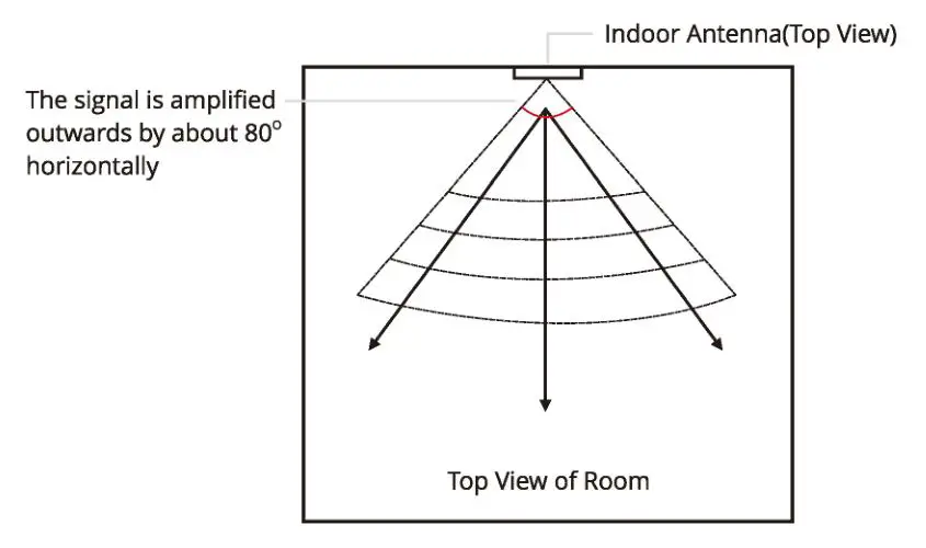
The panel antenna included in this kit will be mounted to the wall. It has a coverage area that is a sector with a tilted angle.
The signal is amplified outwards from the front of the indoor antenna at a horizontal angle of BO-degrees and a vertical angle of 70-degrees.
The height between the floor and the indoor antenna can vary. Follow the steps below to install the indoor antenna.
1. Connect the indoor antenna to the booster using the coaxial cable included in the kit
Note: Push the cable firmly into the jack on both the antenna and the booster, then turn the connector sleeve clockwise until the connectors are tight
2. Move the indoor antenna around to compare the final values from the antenna test results in Part A – the values roughly the same with the indoor antenna connected
Note: If the values decreased, there may be some oscillation issues with the set up – below are some ways to reduce oscillation:
- Increase the distance in-between the outdoor and indoor antennas
- Ensure that the indoor and outdoor antennas are not facing each other
- Use metal barriers between the indoor and outdoor antennas
Optional Indoor Expansion Kit
To expand the indoor coverage area, use the splitter to connect all cables for the signal booster and indoor antennas (only applies to 1 OK/1 SK Smart Link).
Note: Make sure that the gain and power output values did not change significantly before mounting the second antenna
Part C) Finalize the Installation
Finalize the booster, antenna and coaxial installation by using the mounting hardware included in this kit.
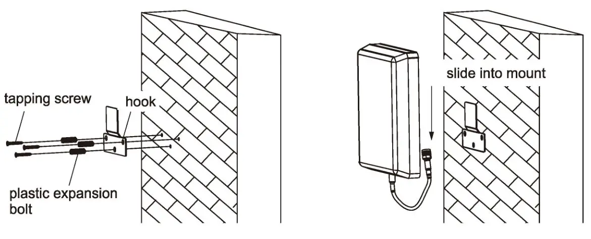
1. Mount the indoor antenna with the screws as shown below:
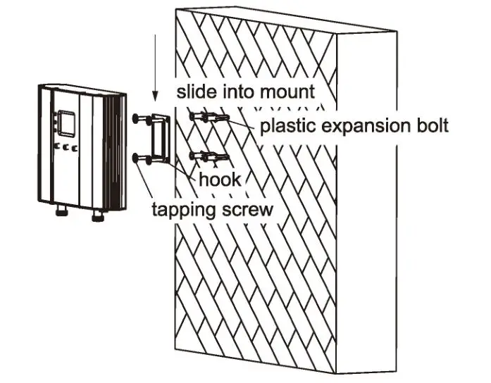
2. Mount the signal booster in a dry and cool area that is easily accessible for maintenance (it should be located near a power outlet)
3. Loosely run the coaxial cable from the indoor and outdoor antenna to the signal booster and secure all connections in the correct port
Professional tips
- Be careful while routing and bending cable – protect the connector by wrapping and securing a towel around the end of the cable
- Keep horizontal cables straight and secure with zip-ties every 3-5 feet
- Keep vertical cables straight and secure with zip-ties every 6-8 feet
- Avoid water damage by using the waterproof tape provided in the kit on the connector attached to the outdoor antenna transmission cable
- Be careful and avoid damaging the pins in the center of the connectors while attaching cables
4. Carefully plug in the power supply to the booster port marked’DC 12V’
Note: For safety purposes, it is recommended to use a 1,000 Joule surge protector between the booster’s power supply and AC power outlet
5. Check to see if all LED indicators are green and that all the following parameters are met:
- There are at least 20 feet worth of vertical separation in between the indoor and outdoor antennas
- The front of the outdoor antenna is NOT facing towards the front of the indoor antenna
- All coaxial cable connections to the antennas and booster are properly connected
Quick Troubleshooting Guide
Eliminate Flashing ISO LCD Display Indicator and Quick Flashing Green, Quick Flashing Red ISO LED Indicator problems:
- Adjust the outdoor antenna direction, keeping it away from the indoor antenna – restart the booster
- Increase the vertical or horizontal distance between the outdoor antenna and the indoor antenna – restart booster.
- Use metal or wall barriers to increase the isolation between the indoor and outdoor antennas – restart booster
- Change the indoor antenna type to an antenna with a more directional antenna pattern – orient the indoor antenna and the outdoor antenna so they are not pointing at each otherThe ISO issues are solved when the ISO LED is “Green” or “Slow Flashing Green” or no flashing ISO legend
Eliminate poor coverage problems when Power “一” legend on LCD and Alarm LED is Green
1. If the signal has not been improved, please check below:
- A weak downlink signal leads to the low output signal level – change the direction or position of the outdoor antenna
- Try replacing the outdoor antenna with a higher gain antenna to increase the amount of signal being received
- Check to see if it is necessary to add more indoor antennas – barriers such as walls can block the signal indoors
- Check the booster to make sure the output power is maximized – the user may need to replace the booster with a more powerful one if the amount of outdoor signal available is limited
2. If the signal in a small section of the building hasn’t been improved, try the following:
- Check to see if the indoor antenna is installed correctly – try moving and adjusting the indoor antenna to improve coverage
- Purchase a HiBoost Expansion kit to extend coverage in specific areas (only applicable to 1 OK SL and 15K SL)
Other Troubleshooting Issues
Reference the chart below to identify the current status of the booster.
LED STATUS INDICATORS
If there are any issues while installing a HiBoost cell phone signal booster, please contact the technical support team through the following channels:
24/7 Online Support: Create a ticket or chat via Signal Supervisor AppPhone: (972) 870-5666 (M-F from 9 am – 5 pm)Email: [email protected]Website: www.hiboost.com

FCC and IC Statements
FCC RF EXPOSURE STATEMENT
This equipment complies with FCC radiation exposure limits set forth for an uncontrolled environment. End users must follow the specific operating instruction for satisfying RF exposure compliance. This transmitter must not be colocated or operating in conjunction with any other antenna or transmitter.
IC RF EXPOSURE STATEMENT
The device 1s compliance with RF exposure limits. The minimum distance from body to use the device is 20 CM.
This equipment has been tested and found to comply with the limits for a Class B digital device, pursuant to part 15 of the FCC Rules. These limits are designed to provide reasonable protection against harmful interference in a residential installation. This equipment generates, uses and can radiate radio frequency energy and, if not installed and used in accordance with the instructions, may cause harmful interference to radio communications. However, there is no guarantee that interference will not occur in a particular installation. If this equipment does cause harmful interference to radio or television reception, which can be determined by turning the equipment off and on, the user is encouraged to try to correct the interference by one or more of the following measures:
- Re-orient or relocate the receiving antenna.
- Increase the separation between the equipment and receiver
- Connect the equipment into an outlet on a circuit different from that to which the receiver is connected
- Consult the dealer or an experienced radio/TV technician for help
Changes or modifications not expressly approved by HiBoost could void the user’s authority to operate the equipment. For a complete list of antennas and cables approved for use with these boosters see Authorized Kitting Options
FCC 27.50(d)(4) Statement: Fixed, mobile, and portable (handheld) stations operating in the 1710-1755 MHz band are limited to 1-watt EIRP. Fixed stations operating in the 1710-1755 MHz band are limited to a maximum antenna height of 10 meters above ground.
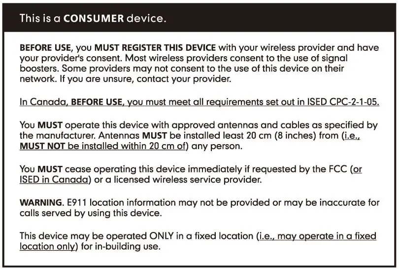
FURTHER INFORMATION ON SIGNAL BOOSTER END-USE REGISTRATION
The following links are the currently active contacts for booster registration with U.S. wireless providers:
https://www.uscellular.com/uscellular/support/fcc-booster-registration.jsphttps://www.sprint.com/legal/fcc_boosters.htmlhttps://www.verizonwireless.com/solutions-and-services/accessories/registersignal-booster/ https://support.t-mobile.com/docs/DOC-9827https://securec45.securewebsession.com/attsignalbooster.com/IC Statement: This device complies with Innovation, Science and Economic Development Canada ICES-003 Compliance Label: CAN ICES-3 (B)/ NMB-3(8).
Please follow the link to access the CPC-2-1-05: http://www.ic.gc.ca/eic/site/smt-gst.nsf/eng/sf08942.html
Technical Specifications

Return and Warranty Policies
30-Day Money-Back Guarantee: If for any reason the performance of any product is not acceptable, the product may be returned to the reseller within 30-days with proof of purchase. Please contact the HiBoost customer support.
3-Year Warranty: HiBoost signal boosters and kits are warranted for 3 years. HiBoost will repair or replace the unit and will cover the cost of delivery for consumers located within the continental U.S and Canada.
Customers can choose to return the signal boosters and kits directly to the manufacturer at the purchaser’s expense with a dated proof of purchase and a Returned Material Authorization (RMA) number supplied by HiBoost. RMA numbers may be obtained by contacting customer support at 972-870- 5666 or [email protected]
This warranty does not apply to any signal boosters or kits determined by HiBoost to have been subjected to tampering, misuse, abuse, neglect, or mishandling that alters or damages physical or electronic properties.
HiBoost is not liable for any Signal Supervisor application network connectivity issues. The cell phone signal booster relies on a strong, continuous and reliable connection to the internet in order to communicate with the cell phone application. For all Signal Supervisor Ap~lication related issues, please check your network strength and call our technical support.
Failure to use a surge-protected AC power strip with at least a 1000 Joule rating will void your warranty. Damage caused by lightning is not covered by this warranty.
 report this ad
All HiBoost products that are packaged with other HiBoost accessory products are intended for resale and used as a single integrated system. Such product kits are required to be sold to the end-users or subsequent reseller as packaged.

![]() HIBOOST6210 N Beltline Rd. #110Irving, TX 75063(972) 870-5666[email protected]www.hiboost.com
HIBOOST6210 N Beltline Rd. #110Irving, TX 75063(972) 870-5666[email protected]www.hiboost.com
References
Register a signal booster | T-Mobile Support
AntennaSearch – Search for Cell Towers & Antennas
Signal Booster, Cell Phone Signal Booster, Cellular Signal Booster-HiBoost Official Store
AT&T Signal Booster
FCC Booster Registration | UScellular
CPC-2-1-05 â Zone Enhancers – Spectrum management and telecommunications
CellReception | Find a better signal.
Signal Booster, Cell Phone Signal Booster, Cellular Signal Booster-HiBoost Official Store
[xyz-ips snippet=”download-snippet”]