
HiBoost Mobile Signal Booster User Manual
WHAT IS INCLUDED
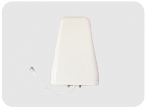
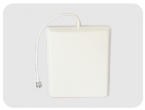
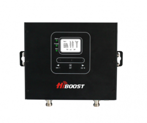
Home10K Outdoor Wide Band Directional Antenna Indoor Wide Band
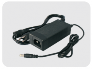
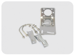
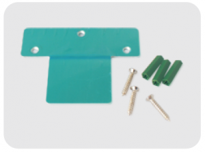
12V/3A Pole and Wall Wall Mount Bracket AC/DC Power Supply Mount Bracket
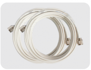
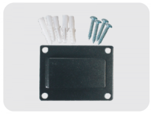
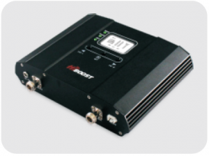
2*30 ft HiBoost200 Booster Mount Hardware Low-loss Cable
We provide all accessories needed for the signal booster. For more information please visit www.hiboostusa.com.Warning: Unauthorized antennas, cables, and/or coupling devices are prohibited by newFCC rules. Please contact FCC for details: 1-888-CALL-FCC.
HOW IT WORKS
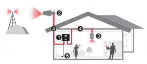
The HiBoost Home 1 OK signal booster is designed to help mobile users improve signal in homes, offices, and other areas where cellular signal is weak or unreliable. The outdoor antenna receives the signal from the nearest cellular tower, amplifies it, and transmits to the signal booster. Then the indoor antenna will receive the signal and retransmit it to your mobile device. The signals produced by your phone are also amplified by the indoor antenna via the booster and outdoor antenna. This manual provides simple installation instructions that will have your signal booster kit running in record time.
HOW TO INSTALL YOUR SIGNAL BOOSTER
1.1 Overview
This manual will help you properly install your signal booster kit. It is important to read through all of the installation steps before installing your equipment. Thoroughly read through the instructions, visualize where all the equipment will need to be installed and do a soft installation by placing the devices where they need to be before mounting any equipment.
- Home 1 OK Signal Booster f)
- Outdoor Wide Band Directional Antenna
- Indoor Wide Band Panel Antenna
- 30ft HiBoost200 Low-loss Cable
- 012V/3A, AC/DC Power Supply
1.2 Installation Preparation
- Before you install Make sure you have sufficient cable length between the proposed outdoor/indoor antenna location and booster connector.
- Make sure the position you install the booster is near to an existing electrical outlet, well ventilated, and away from excessive heat, moisture, and direct sunlight.
Tools Required
Phillips Screwdriver Drill Mobile Phone
Before you get started, you will need to plan the layout of your system. This involves finding the location with the strongest received signal from the cellulartower, as well as antenna, booster, and cable placement.
General installation steps:
- Find the strongest received signal for the location of the outdoor antenna.
- Install the outdoor antenna on the roof to obtain the strongest downlink signal from the local cellular towers. It should also be as far away as possible from where you plan to place the indoor antenna (vertical separation is more important than horizontal separation).
- Install the indoor antennas where you want to improve the signal level.
- Mount the booster, connect the cables from the outdoor antenna and indoor antenna at the designated ports, and connect the booster to the AC supply (make sure all the cables are connected before applying power).
1.3 How to find the location with the strongest received signal
The outdoor signal strength the booster receives directly affects the efficiency of the indoor coverage. That is why it is crucially important to install the antenna at a good location and point it properly towards a tower where signal reception is the strongest. There are many methods that can be used to find the strongest signal from the cellular towers. One is to use the LCD display on the booster that shows the downlink power output of the booster in each band, the other is to use a mobile phone or mobile phone app to test signal strength, and the third is to use a
commercially available signal strength meter. We highly recommend that you use the LCD display on the booster as this method is generally more convenient. However, in situations where the desiredcarrier’s signal is much weaker than the other local signals, using a mobile phone, app, or signal level meter can be a more accurate method of homing in on the best signal for installation
• LCD Display Method
Connect the outdoor antenna to the booster’s outdoor port. Fix the outdoor antenna on the roof of the building and point it to the nearest cell tower. Thenhave a look at the gain and output power value displayed on the booster’s LCD.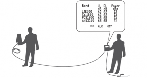
The outdoor antenna receives the strongest signal when the booster’s downlink output power reaches its highest level in each band. If the LCD shows maximum gain and power, and there are not any alarms (no ISO, ALC, OFF legend flashing and no quick flashing green or red in LEDs), it means the present location is the best for ensuring that the booster has maximized performance. The maximum downlink power for Home 1 OK is 12dBm, and the maximum downlink gain is 62-65dB. Note: These showed values may vary dynamically at times between 1-3 dB which is normal due to outdoor signal conditions.
• Mobile Phone Method
You can use a mobile phone to test signal strength on the top of the building. The number of bars on the network indicator will define approximate strength of the received signal. Normally the roof of the building is the best place to receive the strongest signal. As shown on the drawing below, you need to test the signal in the points from A to E, and select the location with the best signal strength for outdoor installation. It is recommended to use a mobile app that can display in a test mode the signal level in dBm units. It is more accurate than checking the
signal bars. For more details refer to http://blog.hiboostusa.com/signal-strengthmeasure- instructions/.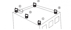
Note: Please try to receive a signal from cell towers that are not overloaded with multiple users. This can be estimated by the population density in the area served by the tower. For example, it is recommended to avoid cell towers near supermarkets, shopping malls, stadiums or any other public places visited by many people regularly. This will help maintain reliable phone call connections and higher speed data services.Mark the strongest received signal as the installation location and direction for the outdoor antenna.
1.4 Install Outdoor Antenna
Install the outdoor antenna at the the location with the strongest received signal.IMPORTANT: Testing the signal 3 times in the desired location before installing the outdoor antenna will help ensure the clearest and most stable signal for phone calls and data transmission.
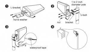
Note: Be sure the cradle is at the desired height and rotated toward the strongest cellular signal before tightening the nuts. Do not over tighten.
1.5 Install Indoor Antenna
Select a place on a wall in the area where you need better reception. Mount the indoor antenna with the included screws as shown in the figure below.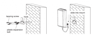
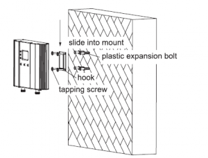
1.6 Install your signal booster
The signal booster should be mounted in an easily accessible area so it’s easy to perform general maintenance. The area is properly ventilated and not exposed to excessive heat, moisture and/or direct sunlight. The optimal area would be on a wall located near a power outlet. Please use a surge protector rated at a minimum of 1000 Joules between the booster’s power adaptor and the AC power outlet on the wall.Mount the booster with the included screws as shown in the figure below.
1.7 Run coaxial cable
Loosely run the supplied coaxial cable from your outdoor antenna to your booster connector marked “Outdoor.” We recommend applying waterproof tape
to fully waterproof the connection. Connect the indoor antenna cables from your indoor antenna to the booster connector marked “Indoor.” Tighten the connection by hand. (After you have tested the system you can permanently secure the coaxial cable). As you route and pull cabling, follow these general guidelines:
- Bend cables and route them smoothly, and protect the outer skin against any damage.
- Keep horizontal cables straight and fasten them with a tie every three to five feet.
- Bind and fasten vertical cables every six to eight feet.
- Waterproof all connectors between outdoor antenna and coaxial cables with waterproof tape to avoid water or other kinds of damage.
- Be careful when plugging the connector in so as not to damage the center pins on the connectors.
1.8 Power up your signal booster
Once all the following precautions have been taken, power on the signal booster.
- Verify that you have left at least 20 feet of vertical separation space between the indoor and outdoor antennas.
- Never point the front of outdoor antenna towards the inside of the indoor antenna.
- Verify that the supplied coaxial cables from both the outdoor antenna and the indoor antenna are properly connected to the signal booster before powering it up.
- Carefully plug in the supplied power adaptor into the signal booster where it is marked ‘DC 12V’ and connect the other end to a power outlet. The LED indicator marked power should light up green.
SIGNAL BOOSTER STATUS
Overview: The booster has a smart startup system. When you have finished the booster system installation and power on the booster, it will start its initialization process to check the received downlink signal from the cell site and the isolation status. This an automatic process designed to ensure its best performance. This will take approximately 3-5 seconds. After the booster starts up, please check if the coverage is good. If it is good, thebooster system installation is complete. If the coverage is not adequate, please fully reread and understand the LCD, LED indications, control buttons, and MGC function on your booster. These will help you identify and solve any potential issues
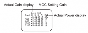
• LCD Features
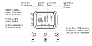
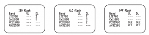
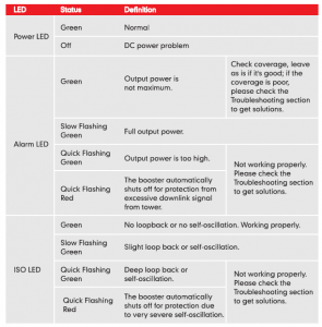
Band: Shows the working frequency bands where the booster is operating. UL/DL: Shows real-time uplink and downlink gain(dB). These values will change slightly as the ALC or ISO makes changes to the gain to optimize coverage.Power: Shows real-time downlink power(dBm) that the booster is delivering to the indoor antenna port. When the booster DL output power is lower than –1 □ dBm, the value will display”—“. ISO: When the system does not have enough isolation between the outdoor and indoor antennas, the “ISO” indicator will be flashing showing that the ISO haslowered the gain in some bands to keep the system from oscillating. Press the “SET” key and the LCD screen will turn on to help with troubleshooting and display “ISO” value showing the current band or bands affected.ALC: When the booster is receiving too much DL power from the tower and the DL booster output is close to saturating, the “ALC” indicators will flash showing that the ALC has lowered the gain to prevent this overload condition. Press the “SET” button and the screen will turn on to help with troubleshooting and show the band or bands affected. OFF: In some rare situations the ALC or ISO will not be able to compensate for an oscillation condition or a downlink overload. When this happens the booster will shut off in the affected band and the LCD “OFF” indicator will flash. Pressing the “SET” button will turn on to help with troubleshooting and display which band or bands are affected.
LED Status
There are 5 operation modes relative to the control keys:
- Press the “SET” key for more than 3 seconds
- Short press on the “SET” key
- Short press on the “DEC-” key
- Short press on “INC+” key
- Simultaneously press on the “DEC-” and “INC+” keys for more than 3 seconds
Since the booster has a self-adaptive smart automatic level control (ALC) and isolation gain processing (ISO), most of the time manual adjustments are not required to achieve good coverage. However, in some cases where the ALC or ISO is working at a very high rate to adjust the gain and the Alarm or ISO LED is flashing more than once a second, a manual adjustment might be desired. When the LCD is in the fixed display mode, press the “SET” key for more than 3 seconds. It will go into the “Gain Setting Mode” and make one of the gain values start to blink.
- Briefly press “SET” key, and the LCD will switch to the next gain value and it will start to blink. (Uplink or downlink gain for a different band).
- Press “INC+” key once shortly and the gain will increase by 1dB, Press “DEC-” once shortly and the gain value will be reduced by 1 dB.
- Press the “SET” key for more than 3 seconds, and the LCD will return to the fixed display mode.
Note: When adjusting the gain manually, please ensure that the uplink gain is equal to or not 5 dB less than the downlink gain setting. This avoids interference with the local cell site tower network. When the LCD is in the fixed display mode, press the “DEC-” and “INC+” key simultaneously for more than 3 seconds, the booster will reset the gain to the default manufacturer settings. When the LCD is in the alarm display mode, press the “SET” key and the LCD screen will turn on to help with troubleshooting and display the alarm indication showing the affected band or bands, press the “INC+” (or “DEC-“) key will switch to different pages.If none of the keys are pushed within 30 seconds, the display will return to the fixed display mode.If none of the control keys are pushed within 5 minutes, the LCD screen will turn off. Pressing any key will return the display to the fixed mode.
TROUBLESHOOTING
Eliminate Flashing ISO legend and Quick Flashing Green, Quick Flashing Red ISOLED problems:
- Adjust the outdoor antenna direction, keeping it away from the indoor antenna. Restart booster.
- Increase the vertical or horizontal distance between the outdoor antenna and indoor antenna. Restart booster.
- Use barriers such as walls to increase the isolation.
- Change the indoor antenna type to an antenna with a more directional antenna pattern. Orient the indoor antenna and outdoor antenna so they point in opposite directions.
- Reduce the booster’s downlink gain using the manual gain controls. Keep the uplink gain value and downlink gain value the same then restart the booster.Note: Uplink gain must be equal to or not less than SdB below the downlink gain to avoid interference with the local carrier’s cell site network. Target: The ISO issues are solved when the ISO LED is “Green” or “Slow Flashing Green” or no flashing ISO legend.
Eliminate Flashing ALC legend and Quick Flashing Green, Quick Flashing Red Alarm LED problems:
- Adjust the antennas’ directions or locations to lower downlink received signal level.
- Slowly reduce the downlink gain using the Manual Gain Controls.
- If the above methods don’t work, reduce the booster’s gain with an external attenuator in line with the outdoor antenna or replace with lower gain antenna.Target: The overload issues are fixed when the Alarm LED is “Green” or “Slow Flashing Green” or no flashing ALC legend. Please note that a “Green” LED indication may result in smaller coverage area. This can be improved by adjusting the outdoor antenna to receive a stronger signal. Eliminate poor coverage problems when Power”—” legend on LCD and Alarm LED is Green: 1. If the signal has not been improved, please check below:
- The weak downlink signal leads to the low output signal level. Change the direction or position of the outdoor antenna. You may also try replacing the outdoor antenna with a higher gain antenna to increase the incoming signal.
- Check to see if it is necessary to add more indoor antennas. Barriers such as walls can block the signal indoors. You should also check the booster to make sure the power is maximized. Try installing more indoor antennas or replace the booster with a higher powered one.2. If the signal in a small section of the building hasn’t been improved, try the
- following:
- Check to see if the indoor antenna is installed correctly. Try moving the antenna to improve coverage.
- Try adjusting the direction the indoor antenna is pointing.
The following accessories are authorized by the FCC to be used with the Home 10K Signal Booster.
| Kit 9-5050Yagi 9dbi Antenna & 50′ 5D CableKit 11-100400Yagi 11dbi Antenna & 100′ 400 CableKit 11-7550Yagi 11dbi Antenna & 75′ 5D CableKit 11-100500Yagi 11dbi Antenna & 100′ 5D CableKit 10-3050Panel 1 0dbi Antenna & 30′ 5D CableKit 10-50400Panel 1 0dbi Antenna & 50′ 400 CableKit 10-5050Panel 1 0dbi Antenna & 50′ 5D CableKit 10-75400Panel 1 0dbi Antenna & 75′ 400 CableKit 10-100400Panel 1 0dbi Antenna & 100′ 400 CableKit 10-7550Panel 1 0dbi Antenna & 75′ 5D CableKit 10-10050Panel 1 0dbi Antenna & 100′ 5D Cable | Kit 9-50400Yagi 9dbi Antenna & 50′ 400 CableKit 9-75400Yagi 9dbi Antenna & 75′ 400 CableKit 9-100400Yagi 9dbi Antenna & 100′ 400 CableKit 9-7550Yagi 9dbi Antenna & 75′ 5D CableKit 9-10050Yagi 9dbi Antenna & 100′ 5D CableKit 7-3050Panel 7dbi Antenna & 30′ 5D CableKit 7-50400Panel 7dbi Antenna & 50′ 400 CableKit 7-5050Panel 7dbi Antenna & 50′ 5D CableKit 7-75400Panel 7dbi Antenna & 75′ 400 CableKit 7-100400Panel 7dbi Antenna & 100′ 400 Cable | Kit 7-7550Panel 7dbi Antenna & 75′ 5D CableKit 7-10050Panel 7dbi Antenna & 100′ 5D CableKit 5-30400Omni 5dbi Antenna & 30′ 400 CableKit 5-3050Omni 5dbi Antenna & 30′ 5D CableKit 5-50400Omni 5dbi Antenna & 50′ 400 CableKit 5-5050Omni 5dbi Antenna & 50′ 5D CableKit 5-75400Omni 5dbi Antenna & 75′ 400 CableKit 5-10400Omni 5dbi Antenna & 100′ 400 CableKit 5-7550Omni 5dbi Antenna & 75′ 5D CableKit 5-10050Omni 5dbi Antenna & 100′ 5D Cable |
Indoor Antenna & Cable Kit Options
| Kit 72-5050-502 Panel 7dbi Antenna with50′ 5D N male& 2-Way SplitterKit 52-5050-502 Whip 5dbi Antenna &50′ 5D Cable& 2-Way SplitterKit 102-5050-502 Panel 1 0dbi Antenna with50′ 5D N male& 2-Way SplitterKit 103-7550-503 Panel 1 0dbi Antenna & 75′ 5D Cable& 3-Way Splitterkit 104-7550-504 Panel 1 0dbi Antenna & 75′ 5D Cable& 3 2-Way Splitter | Kit 73-7550-503 Panel 7dbi Antenna & 75′ 5D Cable& 3-Way Splitterkit 74-7550-504 Panel 7dbi Antenna & 75′ 5D Cable& 3 2-Way SplitterKit 3-30400Omni 3dBi Antenna with 30′ 400 CableKit 3-5050Omni 3dBi Antenna & 50′ 5D CableKit 3-7550Omni 3dBi Antenna & 75′ 5D CableKit 3-10050Omni 3dBi Antenna & 100′ 5D Cable | Kit 3-30400Omni 3dBi Antenna with 30′ 400 CableKit 3-50400Omni 3dBi Antenna & 50′ 400 CableKit 32-50400-502 Omni 3dBi Antenna & 50′ 400 Cable& 2-Way SplitterKit 33-50400-503 Omni 3dBi Antenna & 50′ 400 Cable& 3-Way SplitterKit 34-50400-504 Omni 3dBi Antenna &50′ 400 Cable& 3 2-Way Splitter |
FCC RF EXPOSURE STATEMENT
This equipment complies with FCC radiation exposure limits set forth for an uncontrolled environment. End users must follow the specific operatinginstruction for satisfying RF exposure compliance. This transmitter must not be co-located or operating in conjunction with any other antenna or transmitter.
IC RF EXPOSURE STATEMENT
The device is compliance with RF exposure limits. The minimum distance from body to use the device is 20 CM.
WARNING AND STATEMENT
BEFORE USE, you MUST REGISTER THIS DEVICE with your wireless provider and have your provider’s consent. Most wireless providers consent to the use of signal boosters. Some providers may not consent to the use of this device on their network. If you are unsure, contact your provider. In Canada. BEFORE USE. you must meet all requirements set out in ISED CPC-2-1-05. You MUST operate this device with approved antennas and cables as specified by the manufacturer. Antennas MUST be installed least 20 cm (8 inches) from (i&,,_ MUST NOT be installed within 20 cm of) any person. You MUST cease operating this device immediately if requested by the FCC (Qr ISED in Canada) or a licensed wireless service provider.WARNING. E911 location information may not be provided or may be inaccurate for calls served by using this device. This device may be operated ONLY in a fixed location (i.e .• may operate in a fixed location only) for in-building use.
Note: This equipment has been tested and found to comply with the limits for a Class B digital device, pursuant to Part 15 of the FCC Rules. These limits are designed to provide reasonable protection against harmful interference in a residential installation. This equipment generates, uses and can radiate radio
frequency energy and, if not installed and used in accordance with the instructions, may cause harmful interference to radio communications. However, there is no guarantee that interference will not occur in a particular installation. If this equipment does cause harmful interference to radio or television reception, which can be determined by turning the equipment off and on, the user is encouraged to try to correct the interference by one or more of thefollowing measures:
- Reorient or relocate the receiving antenna.
- Increase the separation between the equipment and receiver.
- Connect the equipment into an outlet on a circuit different from that to which the receiver is connected.
- Consult the dealer or an experienced radionY technician for help.
Changes or modifications not expressly approved by HiBoost could void the user’s authority to operate the equipment.Note: For a complete list of antennas and cables approved for use with these boosters see Authorized Kitting Options page 14.FCC 27.50(d)(4)Statement: Fixed, mobile, and portable (handheld) stations operating in the 1710-1755 MHz band are limited to 1 watt EIRP. Fixed stations operating in the 1710-1755 MHz band are limited to a maximum antenna height of 10 meters above ground.FURTHER INFORMATION ON SIGNAL BOOSTER END-USE REGISTRATIONThe following links are the currently active contacts for booster registration with U.S. wireless providers.https://www.uscellular.com/uscellular/support/fcc-booster-registration.jsphttps://www.sprint.com/legal/fcc_boosters.htmlhttps://www.verizonwireless.com/solutions-and-services/accessories/registersignal- booster/https://support.t-mobile.com/docs/DOC-9827 https://securec45.securewebsession.com/attsignalbooster.com/
IC Statement
This device complies with Innovation, Science and Economic Development Canada ICES-003 Compliance Label: CAN ICES-3 (B)/ NMB-3(8).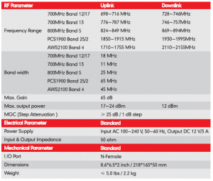
PRODUCT WARRANTY
30-Day Money-Back: All HiBoost products are protected by a 30-day moneyback guarantee. If for any reason the performance of any product is not acceptable, the product may be returned to the reseller with a dated proof of purchase.3-Year Warranty HiBoost signal boosters and kits are warranted for 3 years. Customers can choose to return the signal boosters and kits directly to the manufacturer at the purchaser’s expense with a dated proof of purchase and a Returned Material Authorization (RMA) number supplied by HiBoost. HiBoost will supply two options: repair or replace. Hi Boost will cover the cost of delivery for the consumers located within the continental U.S. This warranty does not apply to any signal boosters or kits determined by HiBoost to have been subjected to misuse, abuse, neglect, or mishandling that alters or damages physical or electronic properties. Failure to use a surge protected AC power strip with at least a 1000 Joule rating will void your warranty. Damage caused by lightning is not covered by this warranty.All HiBoost products that are packaged with other HiBoost accessory products are intended for resale and used as a single integrated system. Such product kits are required to be sold to the end users or subsequent reseller as packaged. RMA numbers may be obtained by contacting Technical Support at 972-870- 5666.
Read More About This Manual & Download PDF:
[xyz-ips snippet=”download-snippet”]