
HOBBYWING X-Rotor F7 Flight Controller User Manual
![]() Thank you for purchasing this HOBBYWING product! We strongly recommend reading through this user manual before use. Because we have no control over the use, installation, or maintenance of this product, no liability may be assumed for any damage or losses resulting from the use of the product.
Thank you for purchasing this HOBBYWING product! We strongly recommend reading through this user manual before use. Because we have no control over the use, installation, or maintenance of this product, no liability may be assumed for any damage or losses resulting from the use of the product.![]() We do not assume responsibility for any losses caused by unauthorized modifications to our product. Besides, we have the right to modify our product design, appearance, features and usage requirements without notification. We, HOBBYWING, are only responsible for our product cost and nothing else as result of using our product.
We do not assume responsibility for any losses caused by unauthorized modifications to our product. Besides, we have the right to modify our product design, appearance, features and usage requirements without notification. We, HOBBYWING, are only responsible for our product cost and nothing else as result of using our product.
WARNINGS
- Read through this user manual before use.
- Ensure all wires and connections are well insulated before connecting the unit to related devices, as short circuit will damage it.
- Please ensure to solder all the wires & connectors well and not get soldering tin on any electronic components if necessary. We won’t be responsible for any damage resulting from soldering and installation.
- Never use the joint pins beyond the ones included in the product box to fix or connect the FC (Flight Controller), ESC and image-transferring board because the heights from pins to sockets between image-transferring board and FC, FC and ESC board is regulated/fixed. If the joint pins are too short, then they will cause the PCBs to deform; if they are too long, then they will affect the connection between pins and sockets and cause damage to relevant devices. We won’t be responsible for the damage or losses resulting from users’ carelessness.
- Never fly the aircraft near crowd; we won’t assume any losses resulting from the crash of the aircraft.
- Never use this unit near heat, moisture, strong acid or alkali and under other environmental conditions that bad for electronic components.
- The unit is ready-to-use (it’s flashed with firmware before leaving the factory), we won’t be liable for any damage resulting from firmware flashing which is carried out by users.
- The FC firmware is an open-source program, users can search relevant technical information on the internet and we won’t provide any technical support beyond the FC hardware.
- This user manual is based on the operation manual for Betaflight and only for reference. For more detailed information, please refer to the original Betaflight manual. Due to firmware update or other reasons, the descriptions for functions may differ, so please always take the official Betaflight manual as standard.
FEATURES
- STM32 F722 MCU allows the FC to run the PID looptime and gyro with higher frequency.
- Onboard OSD microchip which supports the DMA mode allows users to adjust its parameters via the Betaflight software. (Note: the OSD is controlled by the F4 MCU.)
- The FC which supports Betaflight firmware & allows parameter adjustment via Betaflight software is more applicable to FPV racing.
- Onboard Flash chip can record and save flight/black box data allows users to adjust the setup of their aircraft easily.
- Compatible with various receivers like SBUS, SUMH, SUMD, SPEKTRUM1024/2048, XBUS and etc.
- LED strip signal output port allows users to adjust the color & flash mode of the LED strip via the FC.
- Volt/Amp monitoring port allows users to check the battery voltage (BAT port) and current (CRT port, extra current meter is needed).
- Buzzer output port allows users to connect external buzzer(s) to the FC for warning or informing the flight status of the aircraft.
- Micro USB port allows users to connect the FC to a PC to flash firmware and adjust parameters.
- Board load 5V & 10V BEC, both can output 2A. It can supply power for receiver, VTX, LED lamp and others devices.
- Switch module of board load graphic transmission (VTX) can use remote control to controlswitch of graphic transmission.
- Double M3 mounting holes with damping aprons.
- Fit for DJI VTX system plug and play port. (Need fit line).
- Fit for XRotor Micro 40A (20×20) BLHeli_32 4in1 DShot1200 ESC plug and play port
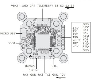
Layout & Different Ports of the FC
- Name: F7 Flight Controller
- Size: 32x30mm
- Mounting Holes: 30.5×30.5mm & 20x20mm
- Firmware Version: HOBBYWING_XROTORF7CONV
- VBAT+: voltage monitoring / FC on board BEC powered port. In general, it’s directly connected to the battery’s “Positive” pole (at this point, the scale value for voltage monitoring on the FC software is set to 110.);
- CRT: Current Sensor in port. It’s connected to the current signal output port of the external voltammeter (at this point, please set the scale value for current monitoring on the FC software as per the voltammeter’s instructions.).
- GND: Ground wire of the FC.
- S1/S2/S3/S4: throttle signal output ports. S1 for ESC#1, S2 for ESC#2, S3 for ESC#3 and S4 for ESC#4.
- TELEMETRY: Use UART6-Rx, receive 4in1 ESC telemetry data.
- RSSI: RSSI signal input.
- 5V: 5V BEC output.
- 3.3V: 3.3V output (it will be available only if the FC inputs the voltage of 5V first).
- TX1, RX1 / TX2, RX2 / TX3, RX3 / TX4, RX4: UART serial port.
- SCL, SDA: IIC clock and data port, it can connect GPS/Magnetic compass with TX4, RX4.
- VOUT: Video-output port of the on-board OSD video signals.
- 10V: 10V BEC output.
- TX5: UART5-TX, can be used for VTX Control (IRC/SA)
- CA1, CA2: Connect Camera 1 and Camera 2 input video signal for on-board OSD. (Default CA1)
- CTL: FC-Camera Control.
- Buzzer+ & Buzzer-: for connecting the buzzer’s “Positive/Negative” poles.
- LED-Strip: for outputting control signals to control the WS2812B LED strip.
- Micro-USB: Micro-USB port.
- Boot: Bootloader button.
- RX5-VTX-SW-3.3V Connection pad: 3.3V and VTX-SW or VTX-SW and RX5 are affiliated welding spot.
Short connection is connected, otherwise disconnected. When neither 3.3V nor RX5 is connected, it is completely disconnected.
Front View:
Back View
Note:
- RX5-VTX-SW-3.3V Connection pad can only choose short connect 3.3V and VTX-SW or VTX-SW and RX5.It cannot short connect all together, otherwise it will damage flight control.
- Under default status, VTX-SW connect 3.3V, VTX switch module is open . When RX5-VTX-SW-3.3V Connection pad completely disconnected , picture transfer switch module is closed.
How to Adjust Parameters

The Betaflight software (as shown below) is needed whether you’re planning to adjust parameters (of the FC) or flash firmware, you can download it from this website: https://github.com/Betaflight.
You need to run this software in Google Chrome, because it’s an extended software of Google. In regard to the software, you can download it from the Google App Store or this website: https://github.com/betaflight/betaflight-configurator.After connecting the FC to a computer, you can click to enter relevant web pages (as shown below) and download the software if you need.
- Latest CP210x Drivers can be downloaded from here.
- Latest STM USB VCP Drivers can be downloaded from here.
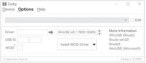
- Latest Zadig for Windows DFU flashing can be downloaded from here
You can start to adjust relevant parameters after you successfully connect the FC to the Betaflight software.Please visit the following websites to download the latest version of Betaflight software:https://github.com/betaflight/betaflight-configuratorhttps://github.com/betaflight/betaflight-configurator/releases
How to this FC to Connect Different Receivers
- How to Set a SBUS receiverIf you’re planning to use a SBUS receiver, please solder the GND/Power/Signal Wire of the receiver to the GND/5V/RX1points on the FC first, then push the “Serial Rx” option button under “UART1” from Gray to Yellow on the “Ports Interface” of the Betaflight software, and set the “Receiver Mode”, “Serial Receiver Provider” on the receiver to “Serial-based Receiver”, “SBUS” respectively on the “Configuration Interface” at last.
- How to Set a Spektrum 1024/2048 ReceiverIf you’re planning to use a Spektrum DSM2/DSMX receiver, then please solder the GND/Power/Signal Wire of the receiver to the GND/3.3V/RX1 points (on the FC) first, and then push the “Serial Rx” option button under “UART1” from Gray to Yellow on the “Ports Interface” of the Betaflight software. And set the “Receiver Mode”, “Serial Receiver Provider” on the receiver to “Serial-based Receiver”, “SPEKTRUM1024/2048 (1024 for DSM2, 2048 for DSMX)” respectively on the “Configuration Interface” at last.How to bind the Spektrum receiver and transmitter:Please key in the following codes on the CLI (Command Line Interface) of the Betaflight software.
- Key in “set spektrum_sat_bind= 9, and then press the “Enter” button on the keyboard.
- Key in “set spektrum_sat_bind_autorst= 0, and then press the “Enter” button on the keyboard.
- Key in “save”, and then press the “Enter” button on the keyboard.Please wait for the FC to restart, disconnect the FC from all the power supplies (including the USB port), and re-connect the FC to the power supply, then you can see the LED on the Spektrum satellite receiver flashes rapidly, turn on the transmitter to bind the transmitter and receiver. If the LED dies out and then comes on solid, then it means that the binding is succeeded. Otherwise, change the number in the code “set spektrum_sat_bind = 9” to any other number (from 1 to 9) and try again.Please connect the FC to the Betaflight software, and key in the following codes on the CLI (Command Line Interface) of the Betaflight software after successfully binding the transmitter and receiver.
- Key in “set spektrum_sat_bind = 0”, and then press the “Enter” button on the keyboard.,
- Key in “save”, and then press the “Enter” button on the keyboard.After that, you can use your spektrum satellite receiver to receive signals.
How to use VTX Switch module
In CLI: Type: resourceLocate UART TX/RX pad resource ID you are using. We wired to RX5 in this demo. RX5 is D02 Note the name of resource and ID.“ resource SERIAL_RX 5 D02 ”Next we will clear that pad from its assigned resource.Type: resource SERIAL_RX 5 NONENext we need to assign the Resource ID to the Custom Mode switch. Using the Resource ID from above. “D02”Type: resource PINIO 1 D02Type: save in CLI and then press enter. Your FC will reboot after applying changes.Now go to Modes and Assign an AUX channel to the USER1 mode. Just like an arm or turtle mode switch. Click SAVE. Now you can control VTX power (10V) turn on or turn off with your transmitter
How to use Camera Switch module
Camera signal default Camera 1 ;through Betaflight Modes setting USER2 Select Switch Camera 1 or Camera 2 .

How to Flash the Firmware
ou need to enter the so-called “DFU” mode when flashing the FC firmware. A software tool called Zadig (you can download it from this website: http://zadig.akeo.ie/) will be needed to switch the driver (of the FC) to the “DFU” mode. In order to switch the driver, you need to take the following steps.
- Press and hold the “BOOT” button on the FC board to connect the FC to a PC.
- Start the “Zadig” software tool on the computer.
- Click “Options”, and then check “List All Devices”

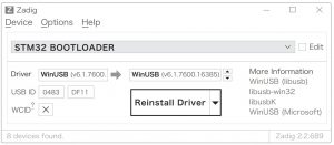
- Select “STM32 BOOTLOADER” on the list.
- Select “WinUSB” under “Driver”, and then click “Reinstall Driver”.
- Close the “Zadig” software tool, and then disconnect the FC from the computer.
- Press and hold the “BOOT” button on the FC board, and then connect the FC to a PC
- Start the “Betaflight” software on the computer and check if the FC is connected to the computer in the “DFU” mode.If yes, then you can flash the firmware.
- For avoiding any damage to the FC, please do not flash the unit with any firmware besides “FLYWOOF7DUAL”.
- The firmware flashing can be carried out in the “online” mode or the “offline mode”, click this link:https://github.com/betaflight/betaflight/releases to download the offline firmware if necessary.

More Info
Please refer to the following websites:http://www.betaflight.ch/ https://github.com/betaflight/betaflight-configuratorhttps://github.com/betaflight/betaflight-configurator/releases https://github.com/betaflighthttps://github.com/betaflight/betaflight https://github.com/betaflight/betaflight/releases
References
The Betaflight Open Source Flight Controller Firmware Project · GitHub
GitHub – betaflight/betaflight-configurator: Cross platform configuration tool for the Betaflight firmware
Betaflight Slack Invite
Releases · betaflight/betaflight-configurator · GitHub
Zadig – USB driver installation made easy
Releases · betaflight/betaflight · GitHub
GitHub – betaflight/betaflight: Open Source Flight Controller Firmware
[xyz-ips snippet=”download-snippet”]