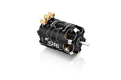
HOBBYWING XERUN D10 Brushless Drift Motor User Manual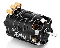
Thanks for purchasing Hobbywing XERUN D10 motor. This sensored brushless power system is very powerful, any improper usage can be dangerous and may damage the product and related devices. Please take your time and read through the following instructions before you start using the motor. We have the right to modify the product design, appearance, features and usage requirements without notification. We, Hobbywing, are only responsible for our product cost and nothing else are result of using our product.
CAUTIONS
- To avoid short circuits, ensure that all wires and joints must be well insulated before connecting the motor to related devices.
- Never allow this product or other electronic components to come in contact with water, oil, fuel or other electro-conductive liquids. If it happens, stop the use of the product immediately and let it dry carefully.
- Read through the manuals of all power devices and chassis and ensure the power configuration is rational before using this unit.
- Never apply full throttle if the pinion gear is not mounted on, because (under the no-load circumstances) high RPMs may get the motor damaged.
- Please connect all the devices carefully, you may not control the vehicle properly or encounter some unpredictable issues like damaged components if any poor connection exists.
- To avoid possible damage (result from overheat) to the product, please control the soldering time within 5 seconds when soldering the motor wires (a soldering iron with the power of at least 60W is needed).
- Stop immediate usage once the casing of the motor exceeds 100℃/212℉ as high temperature may damage the motor and cause the rotor to demagnetize. Hobbywing recommends activating the “Motor Thermal Protection” (of the ESC).
SPECIFICATIONS
| PN | Model (Turns) | KV (No-load) | LiPos | Diameter / Length | Shaft Diameter / Length | Stock Rotor | Poles | Weight(g) |
| 30401134 (Black) | 10.5T | 4600KV | 2-3S | Φ=35.7mm(1.41″) L=52.6mm(2.07″) | Φ=3.175mm(0.125″) L=15.0mm(0.591″) | Φ7-12.2*24.1-BUT*-L1 | 2 | 157g |
| 30401135 (Red) | ||||||||
| 30401136 (Purple) | ||||||||
| 30401137 (Black) | 13.5T | 2900KV
|
Φ5-12.1*24.1-BES*-L3 | 2 | 165g | |||
| 30401138 (Red) | ||||||||
| 30401139 (Purple) |
INSTALLATION & CONNECTION
Please note the following points when mounting or connecting the motor.
- The M3 screws with the length (not longer than 7mm) are needed when mounting the motor onto your vehicle.
- Please pay attention to the relevant marks (on the ESC) when soldering/connecting those output wires to the motor and make sure that you will strictly follow the wiring order (between the ESC & the motor) of “A-A, B-B, and C-C”.
- Please ensure the sensor cable is clean and undamaged when you’re using a sensored ESC. You need to pay attention to the two connectors on the cable when connecting the ESC to the motor.
- Re-check all the connections between the ESC & the motor and ensure that they are all correct before turning on the ESC.
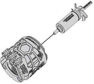
TIMING ADJUSTMENT
The D10 motors provide a wide range of adjustable mechanical timings, the following are the methods & principles you can follow when adjusting the timing.
- You can adjust the motor timing after unfastening the screw on the rear end plate. Please adjust the timing as needed according to the mark (/white lines) at the rear end of the motor and fasten the screw after the adjustment. For obtaining the optimal performance, you can change the output range and characteristic of your power system through adjusting the motor timing.
- Increasing the timing can increase the motor speed (/RPM), while that also increases the motor temperature and reduces the efficiency. A high(er) timing usually requires a high(er) ratio.
- Please ensure your ESC is properly programmed before setting the motor timing. For detailed information about ESC programming, please refer to the user manual of the ESC.
- After the timing adjustment, please ensure that your motor will not get overheat after running a whole pack (i.e. LiPo). You can get the information about the motor temperature via a infra-red temperature gun. If the temperature is too high, please let the motor cool down first and then test again. If the temperature is still too high, then please reduce the timing or increase the FDR (that is to replace the pinion gear with fewer teeth or spur gear with more teeth.).
ASSEMBLY & DIS-ASSEMBLY
The XERUN D10 Motor is very strong in construction but also easy to disassemble for maintenance. We recommend checking the bearings and cleaning the motor periodically.. Please follow the steps (as shown below) to assemble the motor. When disassembling the motor, the sequences are reversed
The XERUN D10 Motor is very strong in construction but also easy to disassemble for maintenance. We recommend checking the bearings and cleaning the motor periodically.. Please follow the steps (as shown below) to assemble the motor. When disassembling the motor, the sequences are reversed.
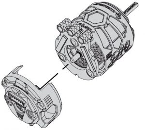
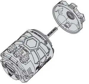
- Install the rear end plate

- Install the rotor
- Install the sensor module
- Install the front end plate
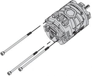
- Fasten the rear end plate with those long screws
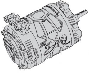
- Finished product
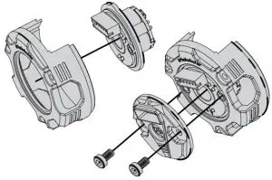
PARTS LIST
The D10 motor contains the following parts:
- Front End Plate x 1Pcs
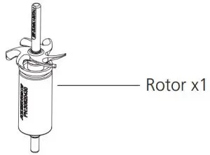
- Rotor x 1Pcs
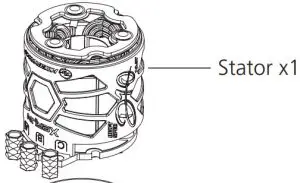
- Stator x 1Pcs
- Sensor Module x 1Pcs
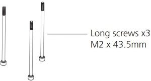
- Long Screws (M2 x 43.5mm) x 3Pcs


OPTIONS
| Optional Parts | PN | Part Name | Applications (/Motors) | Description |
| Rotors | 30820430 | XERUN-D10-Rotor-L1-7-12.2*24.1-BUT | 10.5T, 13.5T | Weak magnetism,Stock rotor for 10.T |
| 30820429 | XERUN-D10-Rotor-L2-7-12.5*24.1-BUS | 10.5T, 13.5T | Feeblish magnetism | |
| 30820431 | XERUN-D10-Rotor-L3-5-12.1*24.1-BES | 10.5T, 13.5T | Moderate magnetism,Stock rotor for 13.T | |
| 30820428 | XERUN-D10-Rotor-L4-5-12.3*24.1-CET | 10.5T, 13.5T | Strong magnetism |
[xyz-ips snippet=”download-snippet”]