
HOBO 12-Bit 4–20 mA Input Adapter User Manual
Test Equipment Depot – 800.517.8431 – 99 Washington Street Melrose, MA 02176 – TestEquipmentDepot.com
 The 12-Bit 420 mA Input Adapter is used for sensors with 420 mA current loop outputs and is designed to work with the HOBO® stations. The input adapter features both a battery-saving switched input and a non-switched input. It also provides a trigger source voltage for controlling power to external sensors. The input adapter has a plug-in modular connector that allows it to be added easily to a HOBO station.
12-Bit 420 mAInput Adapter
S-CIA-CM14Items Included:
- Hook and loop tape
- Cable ties
| Measurement Range* | 4-20 mA |
| Accuracy | ± 0.1 mA (± 0.5% full scale) over full temperature range of -40°C to 75°C (-40°F to 167°F) |
| Resolution | ±4.93 |
| Input Impedance | 124 0 |
| Switched Input | Maximum switch voltage above ground (Pin 2 to Pin 1): 20 VMaximum switch current: 50 mAOn time: 316.6 ms ±3% |
| Sensor Trigger: Source | Voltage: 2.5 V ±2.4%;maximum current: 1 mAOn time: 12.7 ms ±3% |
| Operating Temperature Range | -40°C to 75°C (-40°F to 167°F) |
| Housing | Plastic case; must be placed inside logger enclosure to protect from direct exposure to the weather |
| User Connection | Six-position screw terminal strip (16-30AWG); shielded cable recommended with outside diameter of 3.2 to 3.8 mm (0.125 to 0.150 in.) |
| Dimensions | 4.5 x 4.8 x 1.6 cm (1.8 x 1.9 x 0.6 in.) |
| Weight | 25 g (0.88 oz) |
| Number of Data Channels** | 1 |
| Measurement Averaging Option | Yes |
| Digital Filtering | Automatic digital filtering with 32 readings/sample in 16.6 ms |
| Bits per Sample | 12 |
| Length of Smart Sensor Network Cable** | 14cm (5.5 in.) |
| The CE Marking identifies this product as complying with all relevant directives in the European Union (EU). |
** The input adapter can provide readings as low as 0 mA. This can be helpful when diagnosing sensor issues such as open inputs.** A single station can accommodate 15 data channels and up to 100 m (328 ft) of smart sensor cable (the digital communications portion of the sensor cables), although available space in the enclosure may limit the number of sensors you can attach.
Use the self-adhesive hook-and-loop tape included in the package to mount the input adapter inside the logger enclosure. To mount more than one adapter, use the back of the logger enclosure door. For the HOBO Micro Station, you can place the input adapter inside the logger enclosure and allow it to float freely. It is not necessary to use the hook-and-loop tape.
Mounting Considerations
- If sensor cables are left on the ground, use a conduit to protect against animals, lawn mowers, exposure to chemicals, etc.
- Refer to the logger manual for additional details on mounting.
Insert the cable through the opening at the bottom of the logger enclosure as described in the logger manual. Be sure to provide “drip loops” underneath the logger to prevent water from trickling up the cable and into the logger.
Use the included cable tie to provide strain relief to the cable (or individual wires), as shown below.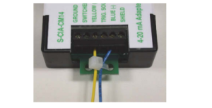
Cable Strain Relief
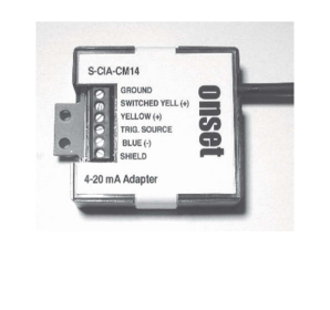
The 12-Bit 420 mA Input Adapter utilizes a 6-position screw terminal block for sensor connections with wire sizes ranging from 16 to 30AWG. Pin numbers, names and descriptions are as follows:
| Pin # | Pin Name | Definition |
| 1 | GROUND | Ground. Used as a common connection. |
| 2 | SWITCHED YELL | Yellow switched. Makes connection to (+) Pin 3 (+ Yellow) once per sample. This helps to conserve external sensor battery life. Maximum 20 V, 50 mA. See Operation for timing diagrams. |
| 3 | YELLOW (+) | Positive current input for sampling. |
| 4 | TRIG. SOURCE | Triggered source. Provides voltage from the logger’s battery to power, or trigger, the external circuitry. Maximum 2.5 V, 1 mA. See Operation below for timing diagrams. |
| 5 | BLUE (-) | Negative current input for sampling. |
| 6 | SHIELD | Connects cable shield for noise suppression and circuit protection. |
A typical remote data logging setup consists of a 12-Bit 4-20 mA Input Adapter, a two-wire 4-20 mA transducer (i.e. flow, pressure, pH, etc.), and an external battery to provide transducer power.
 Switched Connection
If battery conservation is not an issue, or if longer transducer warmup time is required, the following non-switched connection can be made.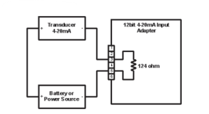
Non-switched Connection
To use the 12-Bit 420 Volt Input Adapter, stop the logger and insert the adapter’s modular jack into an available sensor connection port on the logger.The logger automatically detects the new input adapter the next time you launch it. Launch the logger and verify that the input adapter is functioning correctly. Measurements are recorded in milliamps (mA). See the logger manual for details.
The 12-Bit 420 mA Input Adapter uses digital filtering and optional measurement averaging to reduce the effect of noise and improve accuracy.Regardless of whether measurement averaging is used or not, each sample is comprised of a 300 ms (±3%) warmup period and a 16.6 ms (±3%) sample period. During the sample period, digital filtering is accomplished by taking 32 readings. These readings are then averaged to produce a single measurement, as shown in the following diagram:
Measurement Averaging (Not to Scale)
Optional measurement averaging can be selected at launch. Use measurement averaging if measurements may fluctuate significantly within the logging interval. Measurement averaging helps to prevent the sampling error known as aliasing.To use measurement averaging, set the Sampling Interval to a rate that is faster than the logging interval. When measurement averaging is selected in this way, the adapter takes several measurements during the logging interval and averages them to produce a single logged data point. For example, if the logging interval is 10 minutes and the sampling interval is 1 minute, each recorded data point is the average of 10 measurements.
Note that fast sampling intervals (less than one minute) significantly reduce battery life.For more information about sampling intervals, refer to the logger manual.
The 12-Bit 420 mA Input Adapter can be used with continuously powered 420 mA transducers as well as remote applications with external battery-powered 420 mA transducers. (See figures in Typical Setup.)To take advantage of the switched input, the 420 mA transducer must meet the following criteria:
- The sensor must be able to be powered from the 420 mA loop.
- The sensor must have a warmup time of less than 300 ms.
Using the switched input can significantly reduce external battery consumption because the transducer is powered only during warmup and sampling, as shown in the following diagram, instead of being powered continuously.
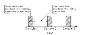 Logging with Switched Input Note
Note
- Using an external battery to drive the 420 mA transducer does not increase the battery life of the logger.
Compared with continuously powering the 420 mA transducer, the average current drain is significantly reduced. For an example of the power savings with and without using the switched input:
- If the logger’s sampling interval is 60 seconds and the worst case current drain for the transducer is 20 mA, then the average current drain will be:transducer current × sample duration ÷ sampling interval20 mA × 0.327 s ÷ 60 s = 0.109 mA
- If we assume that the transducer battery used has a useful capacity of 2000 mAh, the battery life is:battery capacity ÷ average current 2000 mAh ÷ 0.109 mA ÷ 24 hr/day = 764 days
- Without switched input, the battery life would be:2000 mAh ÷ 20 mA ÷ 24 hr/day = 4.1 daysTherefore, using the switched input allows the device to run approximately 186 times longer!
With normal usage, if the adapter is installed correctly, the adapter’s circuitry is protected against excessive moisture and does not require any maintenance or cleaning. However, in an unusually wet environment, excessive moisture can collect in the logger enclosure and adversely affect measurement accuracy and communications in the adapter module.The circuit board is conformal coated to provide limited protection against moisture, but if you observe heavy condensation, consider the following options:
- Verify that the logger is installed properly and sealed according to the instructions given in the logger user manual.
- Consider moving the logger to a location that is better protected from moisture, is better ventilated, or receives some sunlight to help keep the logger dry.
- Apply WD-40, LPS 1, or 711 to the six-position terminal block and the modular connectors to displace moisture and help prevent corrosion. (Other spray lubricants may be appropriate; check product labeling to ensure that it is safe to use on plastics and electronics.)
 report this ad
You should check the accuracy of the 12-Bit 420 mA Input Adapter annually. Verify the accuracy of the input adapter against a known standard, such as a calibrated voltage source. If it is not providing accurate data, it may have been damaged.
 © 20032017 Onset Computer Corporation. All rights reserved. Onset and HOBO are trademarks or registered trademarks of Onset Computer Corporation. All other trademarks are the property of their respective companies.7583-C MAN-S-CIA
[xyz-ips snippet=”download-snippet”]