HOBO MX pH and Temperature Logger MX2501 User Manual
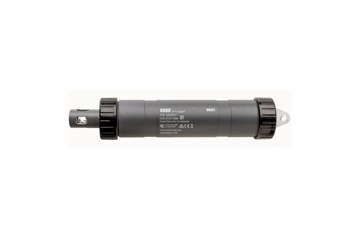
HOBO MX pH and Temperature Logger MX2501
Included Items:
- pH electrode installed and submerged in storage solution
- Extra electrode storage solution
- Anti-biofouling copper guard
- Silicone-based O-ring grease and foam swabRequired Items:
- HOBO connect app
- Mobile device with Bluetooth and iOS, iPad OS®, or Android™ · Deionized or distilled water and squirt bottle
- Calibration solutionsAccessories:
- Replacement pH electrode (MX2500-ELECTRODE)
- Calibration kit with three bottles: pH 4.01, 7.00, and 10.00 calibration solution (MX2500-CAL-KIT) and calibration beakers (MX2500-CAL-BKR)
- Maintenance kit with calibration kit plus storage solution (MX2500-MAINTKIT)
- pH 4.01 calibration solution (MX2500-CAL-4)
- pH 7.00 calibration solution (MX2500-CAL-7)
- pH 10.00 calibration solution (MX2500-CAL-10)
- Electrode storage solution (MX2500-STORE-SOLN)
- Replacement sensor end cap (MX2500-END-CAP)
- Replacement antibiofouling copper guard (MX2500-GUARD)
- Replacement clear storage cap (MX2500-STORAGECAP)
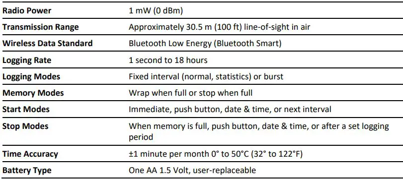
Specifications
Logger Components and Operation

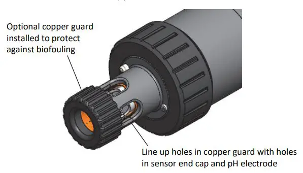
Anti-Biofouling Copper Guard: Use this guard to protect the pH electrode when deploying the logger in water prone to biofouling (see Deploying and Mounting the Logger).
Closure Caps: These caps are screwed onto the sensor end and the mounting end (or top end) of the logger.
Sensor End Cap: This is the bottom end of the logger where the pH electrode is installed, and the temperature sensor and water detection screws are located.
Temperature Sensor: The temperature sensor is located at the base of the sensor end cap.
Water Detection Screws: These two screws on the sensor end cap can detect the presence of water. This allows you to configure the logger in a power-saving mode in which Bluetooth advertising is active only when the logger is removed from water. See Configuring the Logger for details. Note: The logger will check for the presence of water every 15 seconds when the Bluetooth Off Water Detect power-saving mode is selected.
pH Electrode: This is the electrode that is plugged into the logger. The clear plastic end houses a glass pH sensor bulb that must always be placed in storage solution when not deployed in water. See Installing the pH Electrode for details.
Logger Housing: This is the main body of the logger.
Battery Holder: This is where one AA battery is installed under a battery strap (see Battery Information).
Reed Switch: This is used in conjunction with the magnetic switch on the mounting end cap.
LEDs: The blue LED blinks every 4 seconds when the logger is logging (unless Show LED is disabled as described in Configuring the Logger). The blue LED blinks every 8 seconds if the logger is waiting to start logging because it was configured to start “On Button Push” or with a delayed start. The blue LED blinks every 4 seconds when an alarm is tripped (unless the Show LED option is disabled). The blue and red LEDs will blink once when you press the magnetic switch to wake up the logger or will blink four times when you press the switch to start or stoplogging. If you select ![]() in the app, the red LED will be illuminated for 5 seconds.
in the app, the red LED will be illuminated for 5 seconds.
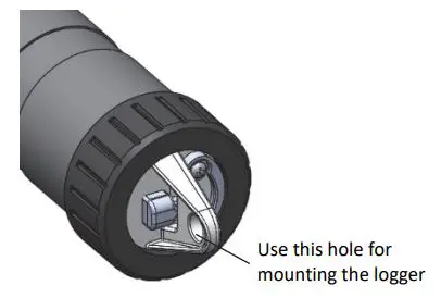
Mounting Hole: Use the hole on the mounting end of the logger to attach it to a cable or cord for deployment (see Deploying and Mounting the Logger).
Switch: This magnetic switch on the mounting end of the logger works in conjunction with the reed switch. Press this switch into the gap beneath the mounting lanyard for 3 seconds to start or stop the logger when it is configured to start or stop “On Button Push” (see Configuring the Logger). Press this switch for 1 second to wake up the logger (if configured with Bluetooth Always Off as described in Configuring the Logger).
Downloading the App and Connecting to a Logger
Install the app to connect to and work with the logger.
- Download HOBO connect from the App Store® or Google Play™.
- Open the app and enable Bluetooth in the device settings if prompted.
- Wake up the logger by pushing the switch on the mounting end of the logger into the gap beneath the mounting lanyard.
- Tap Devices and then tap the logger in the app to connect to it.
If the logger does not appear in the list or if it is having trouble connecting, follow these tips:
- If the logger was configured with Bluetooth Always Off (see Configuring the Logger), make sure the logger is “awake” by pressing the switch for 1 second. This will also bring the logger to the top of the list if you are working with multiple loggers.
- Make sure the logger is within range of your mobile device. The range for successful wireless communication is approximately 30.5 m (100 ft.) in air with full line-of sight.
- Change the orientation of your phone or tablet to ensure the antenna in your device is pointed toward the logger. Obstacles between the antenna in the device and the logger may result in intermittent connections.
- If the logger is in water and configured with Bluetooth Off Water Detect, you must remove the logger from the water to connect to it.
- If your device can connect to the logger intermittently or loses its connection, move closer to the logger, within sight if possible. If the logger is in water, the connection can be unreliable. Remove it from water for a consistent connection.
- If the logger appears in the app, but you cannot connect to it, close the app and power cycle the mobile device. This forces the previous Bluetooth connection to close.
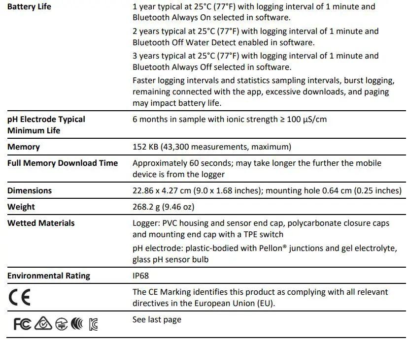
Once the logger is connected, you can:
Important: Before updating the firmware on the logger, check the remaining battery level and make sure it is no less than 30%. Make sure you have the time to complete the entire update process, which requires that the logger remains connected to the device during the upgrade.
Calibrating the LoggerIf the logger is new or a new pH electrode has been installed, you must calibrate the logger with the app before configuring and deploying it. The app will also prompt you to calibrate the
logger if the pH electrode has never been calibrated, the last calibration is more than seven days old, or the logger firmware was updated.
Important: The pH sensor must be kept in storage solution when not being calibrated or deployed in water. The hydration layer surrounding the sensor starts to break down after 10 minutes if the pH sensor is not submerged in storage solution or calibration solution, or deployed in water.
You will need:
- Deionized or distilled water and a squirt bottle to rinse the pH sensor.
- The logger with the pH electrode installed and the copper guard removed.
- Calibration solution (also called buffer solution) poured into beakers. All three buffers are available in a kit (MX2500-CAL-KIT) or individually (MX2500-CAL-4, MX2500-CAL-7, or MX2500-CAL-10).
Important: The logger should be calibrated based on the conditions at the location where it will be deployed. Specifically, if the water temperature is expected to be different than 25°C (77°F), it is important for the calibration buffers to be close to the expected temperature of the analyte (see the chart at the end of this section for the effect of temperature on buffers). Similarly, if the logger will be deployed at an altitude other than sea level, perform the calibration at or near the deployment altitude.
To calibrate the logger:
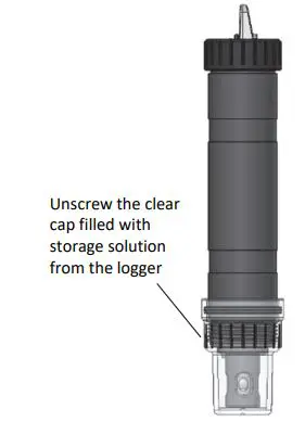
- If the sensor is in the storage solution, unscrew the clear storage cap and remove it from the logger.

- If you removed the clear storage cap, screw the closure cap onto the logger.
- Tap Devices.
- If the logger was previously configured with Bluetooth Always Off, press the switch on the logger to wake it up. If the logger was previously configured with Bluetooth Off Water Detect and it is deployed in water, remove it from water.
- Tap the logger in the app to connect to it.
- Tap if you are not automatically prompted to calibrate the logger.
- Use a squirt bottle to rinse the pH sensor with deionized or distilled water.
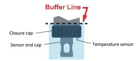
- Place the sensor end of the logger in the pH 7 solution and tap Start. Make sure the sensor end cap, temperature sensor, and closure cap are submerged in the solution as shown in the illustration. Once the pH reading is stable, tap Confirm.
- Rinse the pH sensor with deionized or distilled water.
- If you are using the pH 4 buffer, place the sensor end in the pH 4 solution and tap Start. If you are not using the pH 4 buffer, tap Skip and go to step 12.
- Once the pH reading is stable, tap Confirm. Rinse the pH sensor with deionized or distilled water.
- If you are using the 10 buffer, place the sensor end in the pH 10 solution and then tap Start. Once the pH reading is stable, tap Confirm. If you are not using the pH 10 buffer, tap Skip.
- Verify that the slope and offset is acceptable and tap Save. If the slope and offset are not acceptable, then tap the back arrow and repeat the calibration steps in this section as needed.
- Rinse the pH sensor with deionized or distilled water again.
If you will not be deploying the logger immediately, place the pH electrode in storage solution. Unscrew the sensor end cap installed on the sensor end of the logger. If the clear storage cap is empty, pour in storage solution to the marked fill line. Carefully screw the clear cap with storage solution onto the logger. Only use storage solution in the clear cap; do not use water. Do not use the copper guard when the pH electrode is in storage solution.Notes:
- The date of the last calibration, the slope and offset values, and the buffers used for the calibration listed under the Deployment Information in the Configuration screen for reference.
- Once a logger is connected to the app, a notice appears if the last calibration is more than seven days old prompting you to recalibrate the logger. Although you can postpone the calibration, it is recommended that you recalibrate the logger before configuring it.
- If the status message during calibration indicates the reading is invalid or it never stabilizes, try the following:
- Make sure the sensor is in the correct buffer solution or try rinsing the sensor and restarting the calibration. If the problem persists, clean the sensor (see Maintaining the Logger) and inspect it to make sure it is not damaged.Note: There could be microcracks on the glass bulb of the electrode that may not be visible to the human eye
- Remove the sensor from the calibration solution and clean it (see Maintaining the Logger). Restart the entire calibration process.
- Wait longer to see if it stabilizes, keeping in mind that a pH electrode has a 6-month typical minimum life and may produce unstable readings if it is older than 6 months. The slope and offset values that are provided are the best indication for the condition of the electrode. A healthy electrode has a slope between 85% and 100% and an offset between ±30 mv.
- If the reading reported in app is acceptable for your deployment even though it is reported as unstable, you can tap Stop and then Confirm and proceed with the calibration.
- You can calibrate the logger while it is logging. After the calibration is saved, any new data logged will use the new calibration. Data logged before the new calibration was saved will use the old calibration data. If you do not want data in a single file to be based on more than one calibration, then stop the logger and read it out. You can then calibrate it and reconfigure it.
- pH values of calibration buffers and samples will vary depending on their temperature. It is important that the logger is calibrated in buffers that have the same temperature as that of the sample. To do this, it is necessary to use buffers that have known values at different temperatures. The app will automatically compensate for temperature variances from 25°C (77°F) based on the actual temperature-dependent pH value (from the chart below) of buffers and samples.

Configuring the Logger
Use the app to set up the logger, including selecting the logging options, configuring alarms, and other settings. These steps provide an overview of setting up the logger. For complete details, see the app user’s guide.
- If the logger was previously configured with Bluetooth Always Off, press the switch on the logger to wake it up. If the logger was previously configured with Bluetooth Off Water Detect and it is deployed in water, remove it from water. If you are working with multiple loggers, pressing the button also brings the logger to the top of the list in the app.
- Tap Devices and then tap the logger in the app to connect to it.
- Tap to configure the logger.
- Tap Name and type a name for the logger up to 20 characters (optional). If no name is selected, the logger serial number is used as the name.
- Tap Group to add the logger to a group (optional). Tap Save.
- Tap Logging Interval and choose how frequently the logger will record data unless operating in burst logging mode (see Burst Logging). Note: If you configure an alarm, the logger will use the logging interval you selected as the rate to check for alarm conditions (alarms are not available if burst logging is configured). See Setting up Alarms for more details.
- Tap Start Logging and select when logging will begin:• Now. Logging will begin immediately after tapping Start in the Configure screen.• On Next Logging Interval. Logging will begin at the next even interval as determined by the selected logging interval.• On Button Push. Logging will begin once you press the switch on the logger for 3 seconds.• On Date/Time. Logging will begin on a date and time you specify. Select the date and time. Tap Save.
- Tap Stop Logging and select the options for when logging will end.a. Choose one of two memory options:• When Memory Fills. The logger will continue recording data until the memory is full.• Never (Wrap When Full). The logger will continue recording data indefinitely, with newest data overwriting the oldest. This option is not available if the Logging Mode is set to Burst (see Burst Logging).b. Select On Button Push if you want to be able to stop logging by pushing the switch on the logger for 3 seconds.c. Select one of the following time options for when to stop logging:• Never. Select this if you do not want the logger to stop at any predetermined time frame.• On Date/Time. Select this if you want the logger to stop logging on a specific date and time. Select the date and time.• After. Select this if you want to control how long the logger should continue logging once it starts. Choose the amount of time you want the logger to log data. For example, select 30 days if you want the logger to log data for 30 days after logging begins.d. Tap Save.
- Tap Logging Mode. Select either fixed interval logging or burst logging. With fixed interval logging, the logger records data for all sensors and/or selected statistics at the logging interval selected (see Statistics Logging for details on choosing statistics options). In burst mode, logging occurs at a different interval when a specified condition is met. See Burst Logging for more information. Tap Save.
- Enable or disable Show LED. If Show LED is disabled, the alarm and status LEDs on the logger will not be illuminated while logging (the alarm LED will not blink if an alarm trips). You can temporarily turn on LEDs when Show LED is disabled by pressing the button on the logger for 1 second.
- Select the power saving mode, which determines when the logger will “advertise” or regularly send out a Bluetooth signal for the phone or table to find via the app.• Bluetooth Always Off. The logger will only advertise during logging when you push the switch on the logger. This will wake up the logger when you need to connect to it. This option uses the least battery power.• Bluetooth Off Water Detect. The logger will not advertise when the presence of water is detected. Once the logger is removed from the water, advertising will automatically turn on, thereby not requiring you to push the switch to wake up the logger when you need to connect to it. This option preserves some battery power. Note: The logger will check for the presence of water every 15 seconds when this is option is selected.• Bluetooth Always On. The logger will always advertise. You will never need to push a switch to wake up the logger. This option uses the most battery power.
- Set up an optional alarm to trip when the pH and/or temperature sensor reading rises above or falls below a specified value. See Setting up Alarms for details on enabling sensor alarms.
- Tap to save the configuration settings.
Logging will begin based on the settings you selected. See Deploying and Mounting the Logger for details on mounting and see Reading Out the Logger for details on downloading.
Setting up Alarms
You can set up alarms for the logger so that if a sensor reading rises above or falls below a specified value, the red logger LED will blink and an alarm icon will appear in the app. This can alert you to problems so you can take corrective action.To set an alarm:
- Tap Devices. If the logger was configured with Bluetooth Always Off enabled, push the switch on the logger to wake it up. If the logger was configured with Bluetooth Off Water Detect and is currently underwater, remove it from the water.
- Tap the logger to connect to it and tap .
- Tap a sensor (tap the Enable Logging toggle if necessary).
- Select High if you want an alarm to trip when the sensor reading rises above the high alarm value. Drag the slider or type a value to set the high alarm value.
- Select Low if you want an alarm to trip when the sensor reading falls below the low alarm value. Drag the slider or type a value to set the low alarm value.
- For the Duration, select how much time should elapse before the alarm trips and select one of the following:• Cumulative. The alarm will trip once the sensor reading is out of the acceptable range for the selected duration any time during logging. For example, if the high alarm is set to 85°F and the duration is set to 30 minutes, then the alarm will trip once the sensor readings have been above 85°F for a total of 30 minutes since the logger was configured.• Consecutive. The alarm will trip once the sensor reading is out of the acceptable range continuously for the selected duration. For example, the high alarm is set to 85°F and the duration is set to 30 minutes, then the alarm will only trip if all sensor readings are 85°F or above for a continuous 30-minute period.
- Tap Save.
- In the configuration settings, select one of the following options to determine how the alarm indications are cleared:• Logger Reconfigured. The alarm indication will display until the next time the logger is reconfigured.• Sensor in Limits. The alarm indication will display until the sensor reading returns to the normal range between any configured high and low alarm limits.
- Tap .
When an alarm trips, the red logger LED blinks every 4 seconds (unless Show LED is disabled), an alarm icon appears in the app, and an Alarm Tripped event is logged. The alarm state will clear when the readings return to normal if you selected Sensor in Limits in step 8. Otherwise, the alarm state will remain in place until the logger is reconfigured.
Notes:
- Alarm limits are checked at every logging interval unless burst logging is configured. For example, if the logging interval is set to 5 minutes, then the logger will check the sensor readings against your configured high and low alarm setting every 5 minutes.
- The actual values for the high and low alarm limits are set to the closest value supported by the logger. For example, the closest value to 85°F that the logger can record is 84.990°F. In addition, alarms can trip or clear when the sensor reading is within the specified resolution specifications.
- When you read out the logger, alarm events can be displayed on the plot or in the data file. See Logger Events.
Burst Logging
Burst logging is a logging mode that allows you to set up more frequent logging when a specified condition is met. For example, a logger is recording data at a 5-minute logging interval and burst logging is configured to log every 30 seconds when the temperature rises above 85°F (the high limit) or falls below 32°F (the low limit). This means the logger will record data every 5 minutes as long as the temperature remains between 85°F and 32°F. Once the temperature rises above 85°F, the logger will switch to the faster logging rate and record data every 30 seconds until the temperature falls back to 85°F. At that time, logging then resumes every 5 minutes at the normal logging interval. Similarly, if the temperature falls below 32°F, then the logger would switch to burst logging mode again and record data every 30 seconds. Once the temperature rises back to 32°F, the logger will then return to normal mode, logging every 5 minutes. Note: Sensor alarms, statistics, and the Stop Logging option “Wrap When Full” are not available in burst logging mode.
To set up burst logging:
- Tap Devices. If the logger was configured with Bluetooth Always Off enabled, press the button on the logger to wake it up. If the logger was configured with Bluetooth Off Water Detect and is currently underwater, remove it from the water.
- Tap the logger to connect to it and tap .
- Tap Logging Mode and then tap Burst Logging.
- Select Low and/or High and either type or drag the slider to set the low and/or high values.
- Set the burst logging interval, which must be faster than the logging interval. Keep in mind that the faster the burst logging rate, the greater the impact on battery life and the shorter the logging duration. Because measurements are being taken at the burst logging interval throughout the deployment, the battery usage is similar to what it would be if you had selected this rate for the normal logging interval.
- Tap Save.
- Tap .
Notes:
- The high and low burst limits are checked at the burst logging interval rate whether the logger is in normal or burst condition. For example, if the logging interval is set to 1 hour and the burst logging interval is set to 10 minutes, the logger will always check for burst limits every 10 minutes.
- If high and/or low limits have been configured for more than one sensor, then burst logging will begin when any high or low condition goes out of range. Burst logging will not end until all conditions on all sensors are back within normal range.
- The actual values for the burst logging limits are set to the closest value supported by the logger. In addition, burst logging can begin or end when the sensor reading is within the specified resolution. This means the value that triggers burst logging may differ slightly than the value entered.
- Once the high or low condition clears, the logging interval time will be calculated using the last recorded data point in burst logging mode, not the last data point recorded at the normal logging rate. For example, the logger has a 10-minute logging interval and logged a data point at 9:05. Then, the high limit was surpassed and burst logging began at 9:06. Burst logging then continued until 9:12 when the sensor reading fell back below the high limit. Now back in normal mode, the next logging interval will be 10 minutes from the last burst logging point, or 9:22 in this case. If burst logging had not occurred, the next data point would have been at 9:15.
- A New Interval event is created each time the logger enters or exits burst logging mode. See Logger Events for details on plotting and viewing the event. In addition, if the logger is stopped with a button push while in burst logging mode, then a New Interval event is automatically logged and the burst condition is cleared, even if the actual high or low condition has not cleared.
Statistics Logging
During fixed interval logging, the logger records data for enabled sensors and/or selected statistics at the logging interval selected. Statistics are calculated at a sampling rate you specify with the results for the sampling period recorded at each logging interval. The following statistics can be logged for each sensor:
- The maximum, or highest, sampled value,
- The minimum, or lowest, sampled value,
- An average of all sampled values, and
- The standard deviation from the average for all sampled values.
For example, a logger is configured with the logging interval set to 5 minutes and Fixed Interval Logging and Normal selected for the logging mode. In addition, all four statistics are enabled with a statistics sampling interval of 30 seconds. Once logging begins, the logger will measure and record the actual temperature and pH sensor values every 5 minutes. In addition, the logger will take a temperature and pH sample every 30 seconds and temporarily store them in memory. The logger will then calculate the maximum, minimum, average, and standard deviation using the samples gathered over the previous 5minute period and log the resulting values. When reading out the logger, this would result in 10 data series (not including the mV series): two sensor series (with temperature and pH data logged every 5 minutes) plus eight maximum, minimum, average, and standard deviation series (four for temperature and four for pH with values calculated and logged every 5 minutes based on the 30-second sampling).
To log statistics:
- Tap Devices. If the logger was configured with Bluetooth Always Off enabled, press the button on the logger to wake it up. If the logger was configured with Bluetooth Off Water Detect and is currently underwater, remove it from the water.
- Tap the logger in the app to connect to it and tap .
- Tap Logging Mode and then select Fixed Logging.
- Select Normal to record the current reading for the temperature sensor at the logging interval shown at the top of the screen. Do not select this if you only want to log statistics.
- Select the statistics you want the logger to record at each logging interval: Maximum, Minimum, Average, and Standard Deviation (average is automatically enabled when selecting Standard Deviation). Statistics will be logged for all enabled sensors. In addition, the more statistics you record, the shorter the logger duration and the more memory is required.
- Tap Statistics Sampling Interval and select the rate to use for calculating statistics. The rate must be less than, and a factor of, the logging interval. For example, if the logging interval is 1 minute and you select 5 seconds for the sampling rate, then the logger will take 12 sample readings between each logging interval (one sample every 5 seconds for a minute) and use the 12 samples to record the resulting statistics at each 1-minute logging interval. Note that the faster the sampling rate, the greater the impact on battery life. Because measurements are being taken at the statistics sampling interval throughout the deployment, the battery usage is similar to what it would be if you had selected this rate for the normal logging interval.
- Tap Save.
- Tap .
Setting a Password
You can create an encrypted password for the logger that will be required if another phone or tablet attempts to connect to it. This is recommended to ensure that a deployed logger is not mistakenly stopped or purposely altered by others. This password uses a proprietary encryption algorithm that changes with every connection.
To set a password:
- Tap Devices. If the logger was configured with Bluetooth Always Off enabled, press the button on the logger to wake it up. If the logger was configured with Bluetooth Off Water Detect and is currently underwater, remove it from the water.
- Tap the logger in the app to connect to it. Tap and then .
- Type a password and then tap Set. Only the phone or tablet used to set the password can then connect to the logger without entering a password; all other mobile devices will be required to enter the password. For example, if you set the password for the logger with your tablet and then try to connect to the device later with your phone, you will be required to enter the password on the phone but not with your tablet. Similarly, if others attempt to connect to the logger with different devices, then they would also be required to enter the password. To reset a password, press the button on the logger for 10 seconds or connect to the loggerand tap , then , and tap Reset.
Reading Out the Logger
To download data from the logger:
- Tap Devices.
- If the logger was configured with Bluetooth Always On, continue to step 3. If the logger was configured with Bluetooth Always Off, press the button on the logger for 1 second to wake it up. If the logger was configured with Bluetooth Water Detect and it is deployed in water, remove it from the water.
- Tap the logger in the app to connect to it and tap . The logger will read out the data to the phone or tablet.
- Once the readout is complete, tap HOBO Files and select the file to view it. Tap and then to export and share the data.
Data can also be uploaded automatically to HOBO link, Onset’s web-based software. For details, see the app user’s guide and see the HOBO link help for details on working with data in HOBO link.
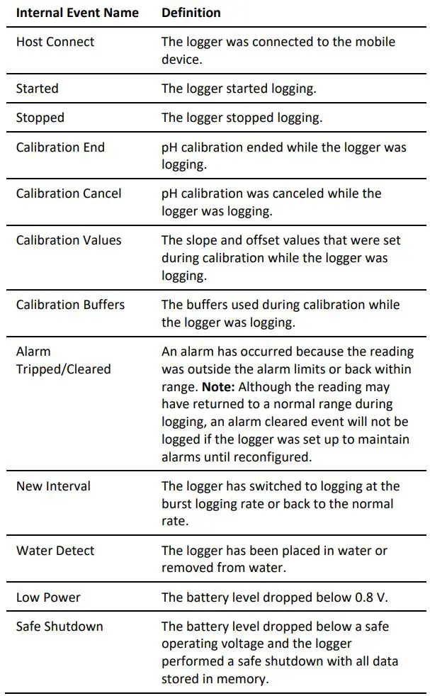
Logger Events
The logger records the following events to track logger operation and status. You can view events in exported files or plot events in the app.To plot events, tap HOBO Files and select a file to open.
Tap![]() and then tap
and then tap![]() . Select the events you want to plot and tap OK.
. Select the events you want to plot and tap OK.
Deploying and Mounting the Logger
Important: The pH sensor must be kept in storage solution when not being calibrated or deployed in water.
Follow these guidelines when deploying the logger:
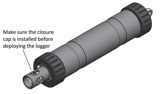
- If the logger is in storage solution, remove the clear storage cap from the logger and replace it with a closure cap as shown in the next diagram before deploying it.
- If your water sample is prone to biofouling, insert the optional copper anti-biofouling guard over the pH sensor as shown. Gently twist the copper guard so that the holes line up with the holes in the sensor end cap and pH electrode. Do not use the copper guard when the pH sensor is being calibrated or in storage solution, or if the sensor is placed in a very small container with still water or in water where copper can affect the environment.
- There are two mounting options:
- Attach a nylon cord or other strong cable to the mounting hole to deploy the logger.
- Alternatively, secure the logger to a pipe or similar surface using cable ties wrapped around the two large grooves in the logger housing.
- The logger should be appropriately secured and protected depending on water conditions and desired measurement location.
Maintaining the Logger
- The pH sensor must be kept in storage solution when not being calibrated or deployed in water. Additional storage solution (MX2500-STORE-SOLN), clear storage caps (MX2500-STORAGE-CAP), and a maintenance kit containing pH 4.01, 7.00, and 10.00 calibration solution and storage solution (MX2500-MAINT-KIT) are available. See www.onsetcomp.com.
- Periodically inspect the logger for biofouling. To clean the logger housing, rinse the logger in warm water. Use mild dishwashing soap if necessary on the logger housing only, taking care not to touch the glass bulb in the pH electrode. Do not use harsh chemicals, solvents, or abrasives. Replacement sensor end caps (MX2500-ENDCAP) and copper guards (MX2500-GUARD) are available if they cannot be cleaned effectively. See www.onsetcomp.com for replacement parts.
- Periodically uninstall the pH electrode from the logger to inspect it for deposits. Clean and recondition it as follows depending on the type of deposits found. To remove a build-up of scale or other dissolve salts, briefly soak the pH sensor in 5% hydrochloric acid. To remove oil deposits, soak the pH sensor in a solution with mild dishwashing soap. Never touch the glass bulb inside the clear plastic end of the probe. Always calibrate the logger after cleaning the pH electrode with anything other than distilled or deionized water.
- The hydration layer surrounding the glass pH sensor bulb in the electrode naturally breaks down over time. Cleaning and reconditioning the electrode as described in in the previous bullet can help to extend its life. It is recommended that you replace the pH electrode after 6 months of continuous use or when the slope and offset readings reported during calibration are consistently not within an acceptable range, even after cleaning. The ideal range for slope is 85% to 100% and for offset is ±30 mv. See Installing the pH Electrode for steps on replacing the electrode (MX2500-ELECTRODE).
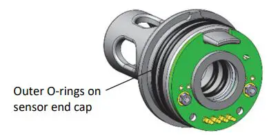
- Periodically add silicone-based grease to the outer O-rings on the sensor end cap shown below. Using your finger, spread a small dot of grease along both outer O-rings.
Installing the pH Electrode
Important: New pH electrodes are uncalibrated. Once a pH electrode is installed in the logger for the first time, it must be calibrated before configuring and deploying the logger (see Calibrating the Logger).To install the pH electrode in the logger:
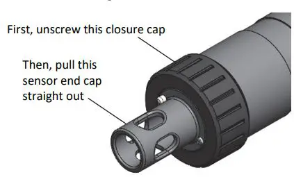
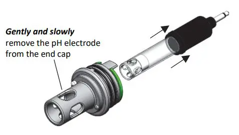
- Unscrew the closure cap over the sensor end cap of thelogger. Pull the sensor end cap straight out from the logger without twisting it.
- Gently and slowly remove the pH electrode from the sensor end cap. (Note: Removing the electrode too quickly could result in unseating the internal O-rings.)
- Use a foam swab dipped in water to clean the internal O-rings. Use the foam swab to spread a small dot of silicone based grease along both the O-rings inside the sensor end cap. Do not use a cotton swab as the fibers on the swab can interfere with the operation of the electrode.
- Remove the replacement pH electrode from the shipping bottle and wipe the outer plastic body dry with a soft paper or cloth towel. Never touch the glass bulb inside the clear plastic end of the probe.
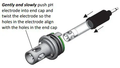
- Remembering not to touch the glass bulb, push the pH electrode gently and slowly into the sensor end cap. You will feel the pH electrode pause as it passes through two internal O-rings inside the sensor end cap (shown with step 3). Make sure the internal O-rings are still in place as the probe is pushed into the sensor end cap. Note: If done too quickly, this process can unseat the internal O-rings. Gently twist the electrode so that the holes in the clear electrode body line up with the holes in the end cap.
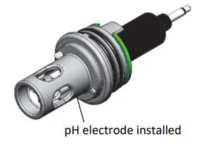
- Continue to gently push the electrode into place until the clear plastic is fully seated in the end cap as shown.
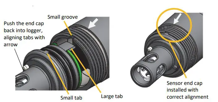
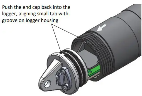
- Push the sensor end cap back into the logger, making sure the small tab in the end cap fits in the small groove in the logger housing. Use the large tab on the end cap and the arrow on the logger housing to help with proper alignment. Do not twist or turn the end cap as you push it straight into position.
- If you will be calibrating the logger immediately: screw the closure cap back on the logger and follow the instructions in Calibrating the Logger.
If you will not be calibrating or deploying the logger immediately:
a. Pour storage solution into the clear storage cap to the marked fill line.
![]()
b. Carefully screw the cap with storage solution onto the logger.Screw on the filled cap
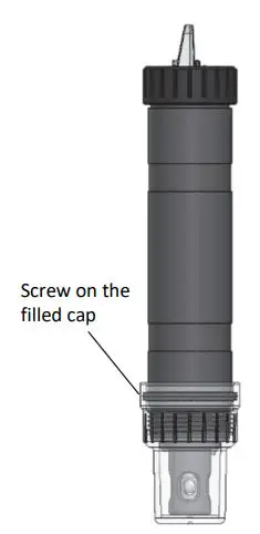
Important: Keep the sensor in storage solution unless you are calibrating the logger or deploying it in water. Only use storage solution in the cap; do not use water. Do not use the copper guard while the sensor is in the cap.
Battery Information
The logger requires one user-replaceable AA 1.5 V alkaline or lithium battery. With a logging interval of 1 minute and at 25°C (77°F), battery life is 1 year with Bluetooth Always On selected, 2 years with Bluetooth Off Water Detect selected, and 3 years with Bluetooth Always Off selected. Expected battery life varies based on the ambient temperature where the logger is deployed, the logging interval, the frequency of connections, downloads, and paging, and the use of burst mode or statistics logging. Deployments in extremely cold or hot temperatures or a logging interval faster than 1 minute can impact battery life. Estimates are not guaranteed due to uncertainties in initial battery conditions and operating environment. To install or replace the battery:
- Wipe the logger clean and dry it completely.
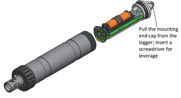
- Unscrew the closure cap on the mounting end of the logger.
- Pull the mounting end cap and attached battery holder straight out from the logger body without twisting. Insert a screwdriver through the mounting hole if you need additional leverage for removing the mounting end cap from the logger.
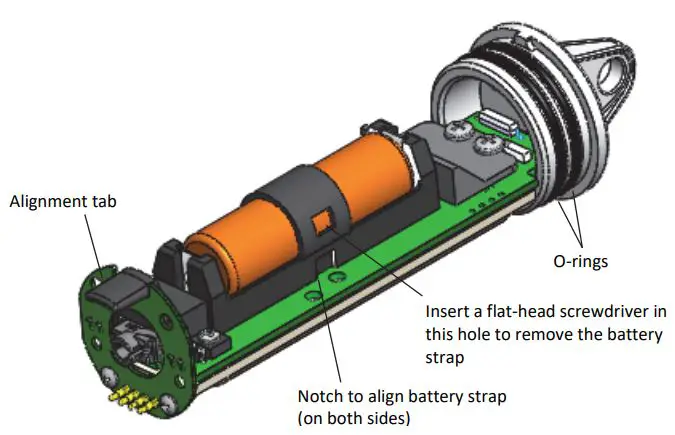
- Remove the battery strap. Insert a flat-head screwdriver into the hole on the strap to lift it off the battery.
- Remove the battery and install a new one, observing polarity.
- Using your finger, spread a small dot of silicone-based grease along both O-rings (shown in step 4) on the mounting end cap.
- Place the battery strap back in place, using the notches on both sides of the holder (shown in step 4) to align it and guide it into place until you hear a click.
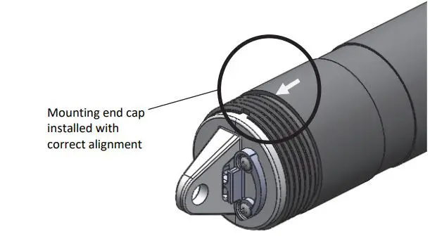
- Reinstall the battery holder and attached mounting end cap. Use the alignment tab on the battery holder (shown in step 4) and the arrow on the logger housing as a guide as you fit the small tab in the mounting end cap into the small groove on the logger housing. Do not twist or turn the mounting end cap as you push it straight into position.
- Screw the closure cap back on the logger.

![]() WARNING: Do not cut open, incinerate, heat above 85°C (185°F), or recharge the lithium battery. The battery may explode if the logger is exposed to extreme heat or conditions that could damage or destroy the battery case. Do not dispose of the logger or battery in fire. Do not expose the contents of the battery to water. Dispose of the battery according to local regulations for lithium batteries.
WARNING: Do not cut open, incinerate, heat above 85°C (185°F), or recharge the lithium battery. The battery may explode if the logger is exposed to extreme heat or conditions that could damage or destroy the battery case. Do not dispose of the logger or battery in fire. Do not expose the contents of the battery to water. Dispose of the battery according to local regulations for lithium batteries.
Federal Communication Commission Interference StatementThis equipment has been tested and found to comply with the limits for a Class B digital device, pursuant to Part 15 of the FCC Rules. These limits are designed to provide reasonable protection against harmful interference in a residential installation. This equipment generates uses and can radiate radio frequency energy and, if not installed and used in accordance with the instructions, may cause harmful interference to radio communications. However, there is no guarantee that interference will not occur in a particular installation. If this equipment does cause harmful interference to radio or television reception, which can be determined by turning the equipment off and on, the user is encouraged to try to correct the interference by one of the following measures:
- Reorient or relocate the receiving antenna
- Increase the separation between the equipment and receiver
- Connect the equipment into an outlet on a circuit different from that to which the receiver is connected
- Consult the dealer or an experienced radio/TV technician for help
This device complies with Part 15 of the FCC Rules. Operation is subject to the following two conditions: (1) This device may not cause harmful interference, and (2) this device must accept any interference received, including interference that may cause undesired operation.
FCC Caution: Any changes or modifications not expressly approved by the party responsible for compliance could void the user’s authority to operate this equipment.
Industry Canada StatementsThis device complies with Industry Canada license-exempt RSS standard(s). Operation is subject to the following two conditions: (1) this device may not cause interference, and (2) this device must accept any interference, including interference that may cause undesired operation of the device.To comply with FCC and Industry Canada RF radiation exposure limits for general population, the logger must be installed to provide a separation distance of at least 20cm from all persons and must not be co-located or operating in conjunction with any other antenna or transmitter
Translation:Article 12Without permission granted by the NCC, any company, enterprise, or user is not allowed to change frequency, enhance transmitting power or alter original characteristic as well as performance to an approved low power radio-frequency device.
Article 14The low power radio-frequency devices shall not influence aircraft security and interfere with legal communications. If found, the user shall cease operating immediately until no interference is achieved. The said legal communications means radio communications is operated in compliance with the Telecommunications Act. The low power radiofrequency devices must be susceptible with the interference from legal communications or ISM radio wave radiated devices.
Translation: The service related to human safety is not allowed because this device may have the possibility of the radio interference.
![]()
1-800-LOGGERS (564-4377) · 508-759-9500 www.onsetcomp.com/support/contact
© 20182020 Onset Computer Corporation. All rights reserved. Onset, HOBO, HOBO link, and HOBO connect are trademarks or registered trademarks of Onset Computer Corporation. App Store and iPad OS are service marks or registered trademarks of Apple Inc. Android and Google Play are trademarks of Google Inc. Bluetooth and Bluetooth Smart are registered trademarks of Bluetooth SIG, Inc. All other trademarks are the property of their respective companies.
 report this ad
Patent #: 8,860,56922511-O
References
[xyz-ips snippet=”download-snippet”]