![]() Photosynthetically Active Radiation (PAR) Smart Sensor (S-LIA-M003)Manual
Photosynthetically Active Radiation (PAR) Smart Sensor (S-LIA-M003)Manual
Test Equipment Depot – 800.517.8431 – 99 Washington Street Melrose, MA 02176 – TestEquipmentDepot.com
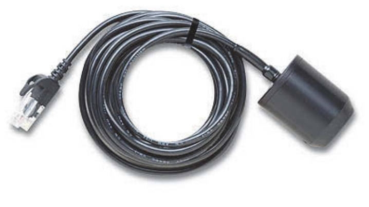
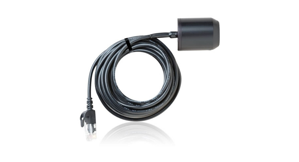
PAR Smart Sensor
S-LIA-M003Accessories:
- Light sensor mounting bracket (M-LBB)
- Light sensor level (M-LLA)
The photosynthetically active radiation (PAR) smart sensor is designed to work with HOBO® stations. The smart sensor has a plug-in modular connector that allows it to be added easily to a station. All calibration parameters are stored inside the smart sensor, which automatically communicates configuration information to the logger without any programming, calibration, or extensive user setup.
Specifications
| Measurement Range | 0 to 2500 µmol/m2/sec, wavelengths 400 to 700 nm (see Plot A) |
| Accuracy | ±5 µmol/m2/sec or ± 5%, whichever is greater in sunlight; Additional temperature induced error ±0.75 µmol/m2/sec/°C from 25°C (0.42 µmol/m2/sec/°F from 77°F) |
| Angular Accuracy | Cosine corrected 0 to 80 degrees from vertical; Azimuth Error <2% error at 45 degrees from vertical, 360 degree rotation |
| Resolution | 2.5 µmol/m2/sec |
| Drift | < ±2% per year |
| Operating Temperature Range | 40° to 75°C (-40° to 167°F) |
| Environmental Rating | Weatherproof |
| Housing | Anodized aluminum housing with acrylic diffuser and O-ring seal |
| Dimensions | 4.1 cm height x 3.2 cm diameter (1 5/8 x 1 1/4 in) |
| Weight | 120 g (4 oz) |
| Bits per Sample | 10 |
| Number of Data Channels* | 1 |
| Measurement Averaging Option | Yes |
| Cable Length Available | 3.0 m (9.8 ft) |
| Length of Smart Sensor Network Cable* | 3.0 m (9.8 ft) |
| The CE Marking identifies this product as complying with all relevant directives in the European Union (EU). |
A single HOBO station can accommodate 15 data channels and up to 100 m (328 ft) of smart sensor cable (the digital communications portion of the sensor cables).
Typical Quantum Response
The PAR smart sensor is designed to detect photons between 400-700 nm in wavelength. Ideally, the sensor would count photons with equal efficiency between 400-700 nm and no photons would be counted outside this range. However, in reality, this sensor undercounts photons between 400-550 nm and between 670-700 nm, and it overcounts photons between 550-670 nm. In most applications (where the sensor is used in natural sunlight) the error is not significant.
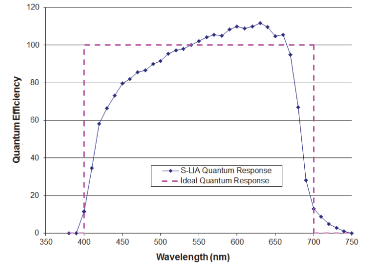 Plot A: PAR Smart Sensor Typical Quantum Response
Mounting
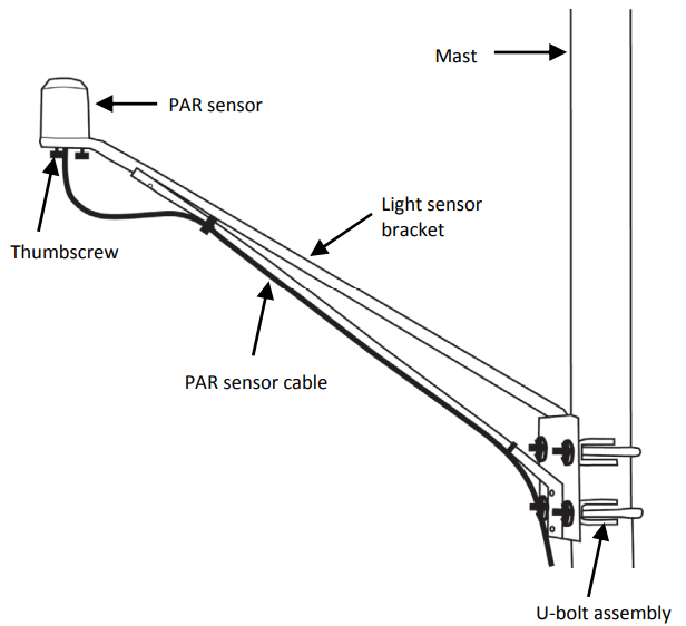
Bracket MountingIt is recommended that you mount the PAR smart sensor with the light sensor mounting bracket (M-LBB) on a pole or tripod. To mount the PAR smart sensor using the bracket:
- Attach the light sensor bracket to a 1¼ inch – 15/8 inch pole with the provided U-bolts.Note: The light sensor bracket can also be mounted on a flat, vertical surface using four screws.
- Position the light sensor on top of the light sensor bracket with its cable running through the slot in the bracket.
- Using the two screws supplied, attach the sensor to the bracket through the two holes on either side of the slot.Note: Do not completely tighten the screws until you level the light sensor.
- Position the bracket so it faces toward the equator, minimizing the chance of shading.
- Mount the light sensor bracket on the mast with the two Ubolt assemblies, mounting it high enough on the mast to avoid the possibility of shading the light sensor.Note: If you mount the light sensor above eye level, it is recommended that you use a step ladder or other secure platform when leveling the sensor so that you can clearly view the light sensor level (M-LLA).

PAR Smart Sensor (S-LIA-M003) Manual
- Make sure the screws holding the sensor to the mounting bracket are loose.
- Place the light sensor level on the light sensor.
- Adjust the height of the thumbscrews to level the sensor (start with the thumbscrews protruding about 1/16 inch from the bracket).
- Once the sensor is near level, tighten the Phillips head screws.
- Check the light sensor level and repeat above steps if necessary.
- When the light sensor is level, remove the light sensor level from the light sensor.
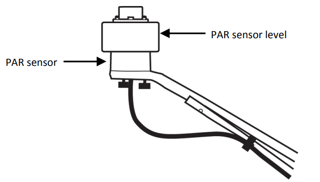
Leveling the PAR Smart Sensor on the Light Sensor Bracket
Specialized Application Mounting
To mount the light sensor using a mounting plate of your own design:
- Drill a 0.56 (9/16) inch hole in the middle of the plate, then drill two #25 holes 1.063 (1-1/16) inches apart on either side of the center hole. Cut a 0.31 (5/16) inch-wide slot in the mounting plate as shown below. The plate should be a thickness of 1/8 inch or less.
- Slide the sensor through the 0.31 (5/16) inch-wide slot.
- Attach the sensor using two 6-32 x 3/8 inch screws and lock washers (not included).
- Shim the sensor as necessary to level it
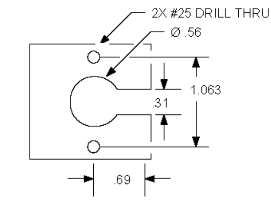 Recommended Mounting Plate Dimensions
Mounting Considerations
- Small errors in alignment can produce significant errors. Be certain that the sensor is mounted level.
- Mount the light sensor where it will not be in a shadow.
- If possible, avoid locating the sensors in dusty locations.Dust, pollen, and salt residue that collect on the top of the sensor can significantly degrade accuracy.
- Refer to the station manual and Tripod Setup Guide for more information regarding setting up stations.
Connecting the Sensor to a Station
To connect the sensor to a station, stop the station from logging and insert the smart sensor’s modular jack into an available smart sensor port on the station. See the station manual for details on operating stations with smart sensors.
Operation
The PAR smart sensor supports measurement averaging. When measurement averaging is enabled, data is sampled more frequently than it is logged. The multiple samples are then averaged together and the average value is stored as the data for the interval. For example, if the logging interval is set at 10 minutes and the sampling interval is set at 1 minute, each recorded data point will be the average of 10 measurements.Measurement averaging is useful for reducing noise in the data. It is recommended that you use measurement averaging whenever the PAR smart sensor is used in an area where the light level can vary quickly with respect to the logging interval (for example, under a partial plant canopy or during partly cloudy conditions). Note that fast sampling intervals less than 1 minute may significantly reduce battery life. See the station manual for more details about battery life.
Maintenance
Dust on the sensor will degrade sensor accuracy. Periodically inspect the sensor, and if necessary, gently clean the diffuser with a damp sponge. Do not open the PAR smart sensor as there are no user-serviceable parts inside.
![]() Warning: DO NOT use alcohol, organic solvents, abrasives, or strong detergents to clean the diffuser element on the light sensor. The acrylic material used in the light sensors can be crazed by exposure to alcohol or organic solvents. Clean the sensor only with water and/or a mild detergent such as dishwashing soap if necessary. It is recommended that you use vinegar to remove hard water deposits from the diffuser element. Under no circumstances should the smart sensor be immersed in any liquid.
Warning: DO NOT use alcohol, organic solvents, abrasives, or strong detergents to clean the diffuser element on the light sensor. The acrylic material used in the light sensors can be crazed by exposure to alcohol or organic solvents. Clean the sensor only with water and/or a mild detergent such as dishwashing soap if necessary. It is recommended that you use vinegar to remove hard water deposits from the diffuser element. Under no circumstances should the smart sensor be immersed in any liquid.
Verifying Sensor Accuracy
It is recommended that you check the accuracy of the PAR smart sensor annually. The PAR smart sensor cannot be user-calibrated. Onset uses precision components to obtain accurate measurements. If the smart sensor is not providing accurate data, then it may be damaged or out of calibration.
 report this ad
![]()
© 20012016 Onset Computer Corporation. All rights reserved. Onset and HOBO are trademarks or registered trademarks of Onset Computer Corporation. All other trademarks are the property of their respective companies.
PAR Smart Sensor (S-LIA-M003) Manual5942-G MAN-S-LIA
[xyz-ips snippet=”download-snippet”]