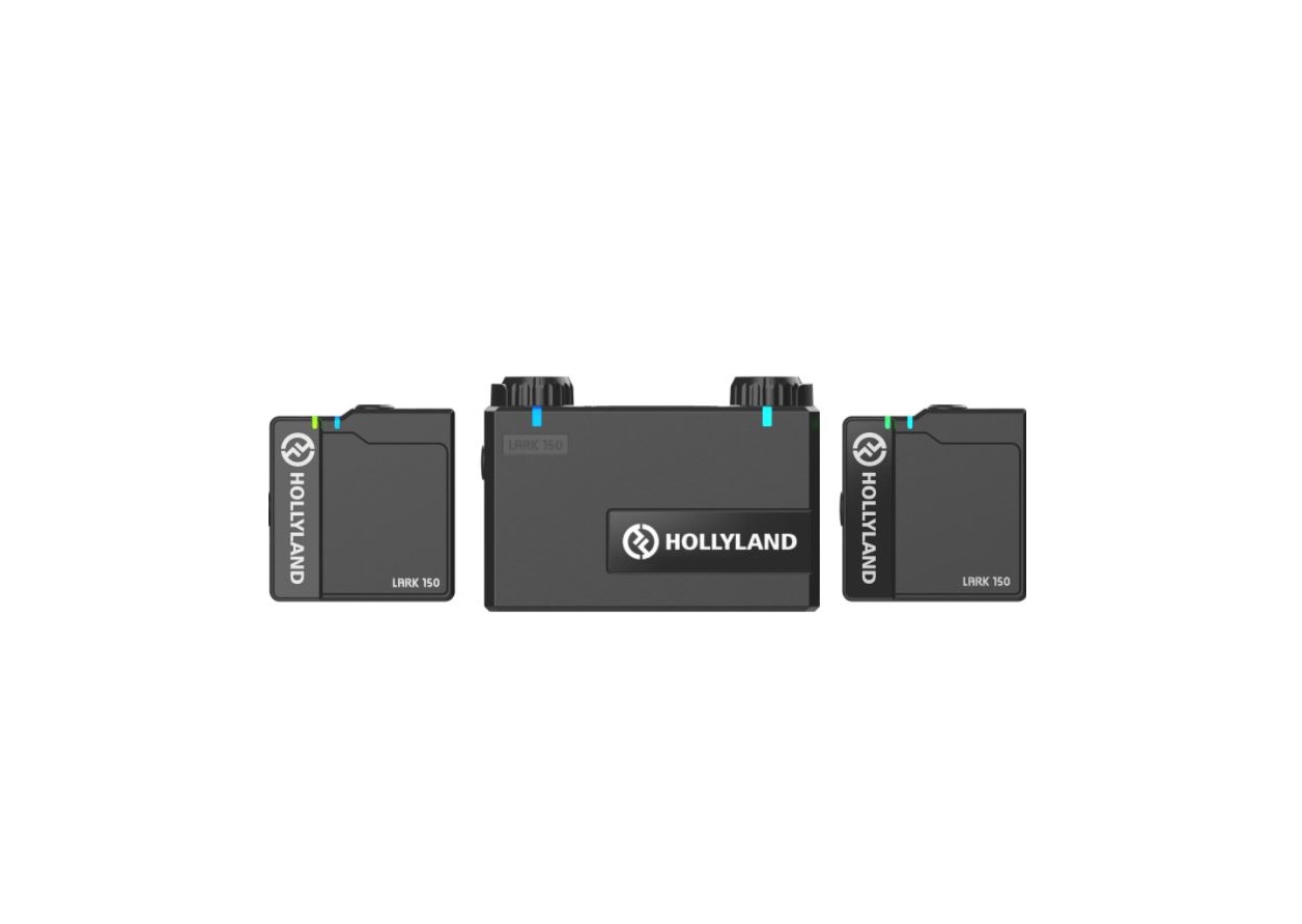
HOLLYLAND LARK 150 2-Person Compact
Digital Wireless Microphone
System User Manual

Specific
FOREWORDThank you for purchasing Hollyland LARK 150 wireless microphone. Please read this instruction carefully before using the product. Wish you have a pleasant experience.
KEY FEATURES
- 5ms Latency with up to 320ft Range
- 2 TX & 1 RX Combo
- 2.4GHz Digital Wireless Transmission with Clear Sound Under Any Conditions
- Mini Size with Lightweight
- Professional-Grade Sound Quality
- Built-In Lithium Batteries, with an Ultra Long Run Time
- 21-Stage Digital Gain Adjustment
- Contact Charging Case
- In-Built Mic and LavMic Switching Automatically
- Multiple Systems Using in One Location
PACKING LIST
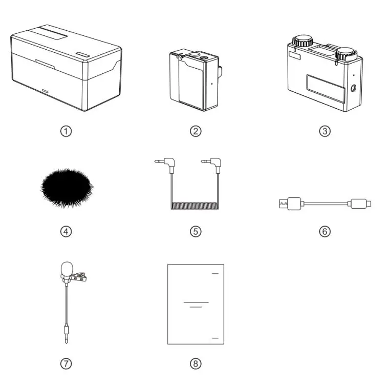
PACKING LIST OF TWO TRANSMITTERS AND ONE RECEIVER
- Charging Case X1
- Transmitter X2
- Receiver X1
- Furry Windshield X2
- 3.5mm TRS Cable X1
- USB Type-A to Type-C Cable X1
- Lavalier Microphone X2
- User Guide X1
The exact quantity may vary on products configuration. Please take the actual quantity as standard.
PRODUCT INTERFACES
![]()
A: TRANSMITTER
- Power Indicator Red: Low Battery, Green: Safe Battery Status, Orange: Charging
- Link Indicator Blue/Cyan Flashing: Disconnected, Blue/Cyan: Connected, Orange: MIC Mute
- In-built Microphone
- 3.5mm Audio Input Port
- Power Button (Press for 3s to Switch On/Off, Click to Mute)
- Reset Button
- Installed Belt Clip
- Charging/Upgrade Contact
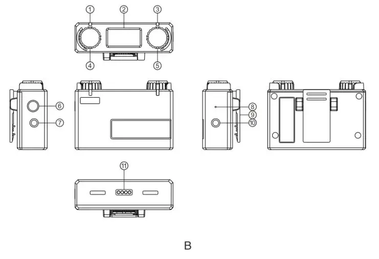
B: RECEIVER
- Link Indicator (Left Channel)
- Display Screen
- Link Indicator(Right Channel)
- Volume Knob Left Channel: Adjust the Volume of the Left TX /Recording Mode Switch Button: Press to Switch the Recording Mode /Left TX Mute Button: Click to Mute the Left TX
- Volume Knob (Right Channel): Adjust the Volume of the Right TX /Channel Switch Mode: Press to Switch the Channel when Stereo Mode /Right TX Mute Button: Click to Mute the Right TX
- Power Button (Press for 3s to Switch On/Off)
- 3.5mm Headphone Monitoring Port
- Reset Button
- Belt Clip
- 3.5mm Audio Output Port
- Charging/Upgrade Contact

C: CHARGING CASE
- Power Indicator Red: Low Battery, Green: Safe Battery Status, Orange: Charging
- USB Type-C Port for Charging
- Reset Button
- TX Charging Slot
- RX Charging Slot
- TX Charging Slot
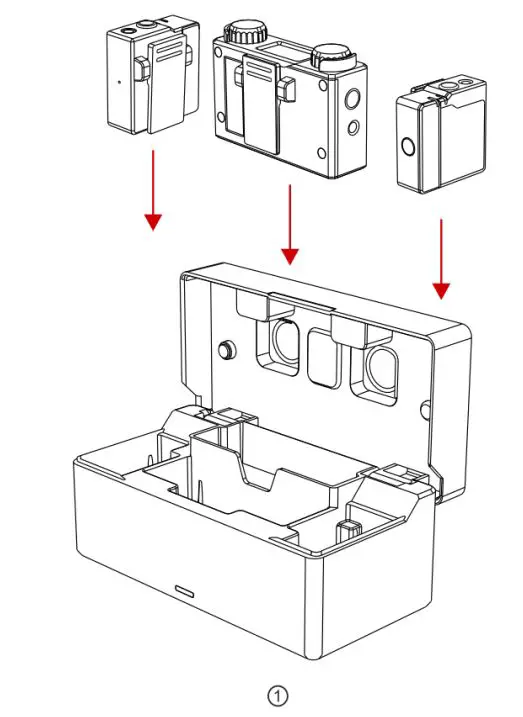
PRODUCT INSTALLATION
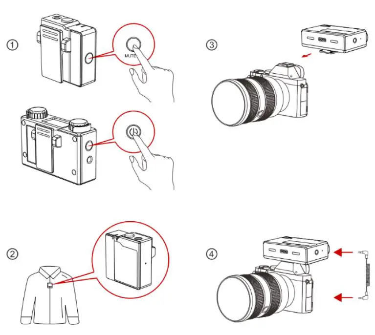
- Press Power Button of TX/RX for 3s to switch on.
- Install TX as Figure2.
- Install RX on the Camera.
- Connect the 3.5mm Audio output port of RX with 3.5mm Audio input port of the camera by 3.5mm TRS cable.
DISPLAY INTRODUCTION

A: Display of RX
- Current Recording Mode of RX
- RX Battery Status
- Cyan TX Signal Strength Status
- Cyan TX Battery Status
- Cyan TX Input Volume Status
- Blue TX Battery Status
- Blue TX Signal Strength Status
- Blue TX Input Volume Status The TX color displayed on main display screen of RX relates to the channel switch and recording mode, the indicators of RX represents the corresponding TX
B: DISPLAY OF RX CHARGING CASE
- Identification of Charging Case
- Charging Case Battery Status (Orange: Charging, Green: Full-Charged)
- Left TX Battery Status (Orange: Charging, Green: Full-Charged)
- RX Battery Status (Orange: Charging, Green: Full-Charged)
- Right TX Battery Status (Orange: Charging, Green: Full-Charged)
OPERATING GUIDENCE
(1) PAIRING
- Put TX and RX into the charging case at the same time, the unpaired devices will be paired automatically.
- Display “√” when pair successfully.
- Display “X” when pair failed.

(2) CHARGING
- It means low battery when the power indicator or the battery icon of RX display screen is red.
- TX and RX will be charged when placed into charging case.
- The indicator of TX will display orange when charging. After placed into the charging case, TX, RX and charging case’s current battery status will be displayed on the screen of RX.
- When TX and RX are fully charged, the devices will automatically enter sleep mode.
- When taking out or putting in TX or TX, the device will automatically wake up and start up.
- The indicator of charging case will display red and stop charging TX or RX when the battery energy is less than 10%.
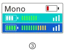
 (3) Mono Mode
 (3) Mono Mode
- After taking out, start up and successfully paired TX and RX.
- Long press left button for 3s to recording mode. Switch successful when the screen displayed “Mono”.
- At this time RX switched to mono mode, both left and right channel outputs two audios of TX.
- Volume of TX corresponds the indicator could be adjustable at this time by knob.

(4) Safety Track Mode
- After taking out, start up and successfully paired TX and RX.
- Long press left button for 3s to recording mode. Switch successful when the screen displayed “ST”.
- At this time RX switched to ST mode, both left and right channels output two audios of TX, but the sound of right channel is 6dB less than left channel, in order to make sure one of the channels is in the safe output volume.
- Volume of TX corresponds the indicator could be adjustable at this time by the knob.

(5) Stereo Mode
- After taking out, start up and successfully paired TX and RX.
- Long press left button for 3s to recording mode. Switch successful when the screen displayed “Stereo”.
- At this time RX switched to Stereo mode. Left side of display screen corresponds to left channel output, right side of display screen corresponds to right channel output.
- Left knob controls output volume of left TX which corresponds left channel, right knob controls output volume of right TX which corresponds right channel.
- Long press right button for 3s can exchange left and right channels’ output and the TX info displayed on the main screen. The original TX on the left will be displayed on the right, the volume knob control will also be exchanged.
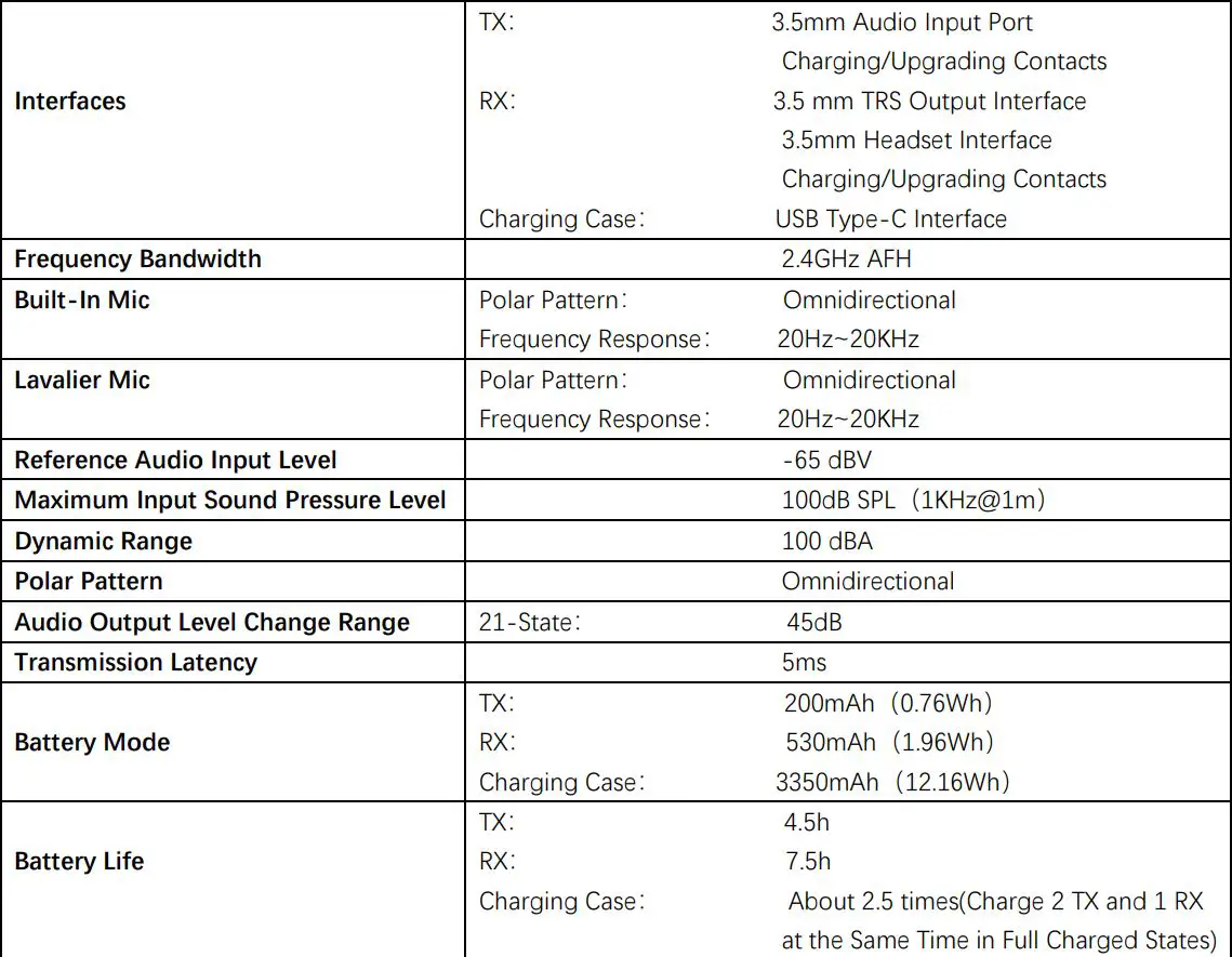
PARAMETERS
Warningschanges or modifications not expressly approved by the party responsible for compliance could void the user’s authority to operate the equipment. This device complies with Part 15 of the FCC Rules. Operation is subject to the following two conditions:
(1) this device may not cause harmful interference, and(2) this device must accept any interference received, including interference that may cause undesired operation.
 report this ad
Note: This equipment has been tested and found to comply with the limits for a Class B digital device, pursuant to Part 15 of the FCC Rules. These limits are designed to provide reasonable protection against harmful interference in a residential installation. This equipment generates, uses, and can radiate radio frequency energy, and if not installed and used in accordance with the instructions, may cause harmful interference to radio communications. However, there is no guarantee that interference will not occur in a particular installation. If this equipment does cause harmful interference to radio or television reception, which can be determined by turning the equipment off and on, the user is encouraged to try to correct the interference by one or more of the following measures:– Reorient or relocate the receiving antenna.– Increase the separation between the equipment and receiver.– Connect the equipment into an outlet on a circuit different from that to which the receiver is connected. – Consult the dealer or an experienced radio/TV technician for help.
[xyz-ips snippet=”download-snippet”]