Holyrood Power Management Board User Manual
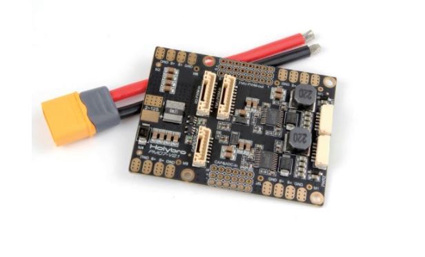
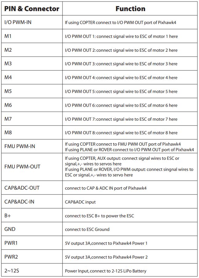
Connect the output of a Power Management Board (PM board) that comes with the kit to one of the POWER bricks of Pixhawk 4 using a 6-wire cable as shown. The PM input 2~12S will be connected to your LiPo battery. The connections of Power Management Board, including power supply and signal connections to the ESCs and servos, are explained in the table below. Note that the PM board don’t supply power to the servos via + and – pins of FMU PWM-OUT. The image below shows the power management board provided with Pixhawk 4.
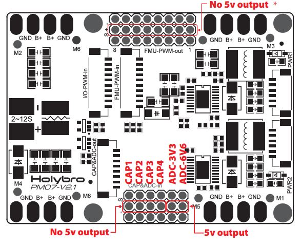 * Note: If using a plane or rover, the 8 pins power rails of FMU PWM-OUT along with a BEC equipped ESC or a standalone 5V BEC or a 2S LiPo battery must be used to supply power to servos. Be careful with the voltage of servo you are going to use here.
Package Include:
PM07 board*180mm XT60 connector wire*1
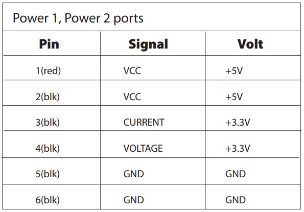
The pinout of Pixhawk4’s power ports is shown below. The CURRENT signal should carry an analog voltage from 0-3.3V for 0-120A as default. The VOLTAGE signal should carry an analog voltage from 0-3.3V for 0-60A as default.
The VCC lines have to offer at least 3A continuous and should default to 5.1V. A lower voltage of 5V is still acceptable, but discouraged.
Specifications
PCB Current: total 120A outputs (MAX)UBEC 5v output current :3AUBEC input voltage : 7~51v (2~12s LiPo)Dimensions:68*50*8 mm Mounting Holes:45*45mmWeight: 36g
[xyz-ips snippet=”download-snippet”]