Home Controls O2TML Installation Guide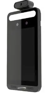
Quick Installation Guide

This device is not intended for use in the diagnosis of any disease or other conditions or in the cure, mitigation, treatment, or prevention of any disease.
WarningThis camera should be installed by qualified personnel only. All the examination and repair work should be done by qualified personnel. Any unauthorized changes or modifications could void the warranty.
StatementThis guide is for reference only. Product, manuals and specifications may be modified without prior notice. Speco Technologies reserves the right to modify these without notice and without incurring any obligation. Speco Technologies is not liable for any loss caused by improper operation.
Regulatory InformationFCC conditions: This device complies with part 15 of the FCC Rules. Operation is subject to the following two conditions: This device may not cause harmful interference. This device must accept any interference received, including interference that may cause undesired operation. FCC compliance: This equipment has been tested and found to comply with the limits for a digital device, pursuant to part 15 of the FCC Rules. These limits are designed to provide reasonable protection against harmful interference. This equipment generates uses and can radiate radio frequency energy and, if not installed and used in accordance with the instruction manual, may cause harmful interference to radio communication. However, there is no guarantee that interference will not occur in a particular installation. If this equipment does cause harmful interference to radio or television reception, which can be determined by turning the equipment off and on, the user is encouraged to try to correct the interference by one or more of the following measures:
- Reorient or relocate the receiving antenna.
- Increase the separation between the equipment and receiver.
- Connect the equipment into an outlet on a circuit different from that to which the receiver is connected.
Note:Before installation, check the package and make sure that all components are included. Contact your rep or Speco customer service department immediately if something is broken or missing in the package.
Do not drop the camera or subject it to physical shock.Keep away from liquid while in use.Do not touch the screen with sharp objects.If cleaning is necessary, please use clean cloth to wipe it gently, avoiding water or alcohol.
Package
- Device

- Quick Start Guide
- QR code for manual
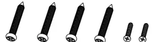
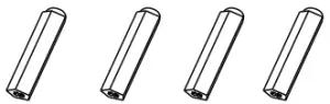
- Tapping Screw×4Screw (KM3*7)×2
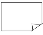
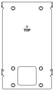
- Drill Template
- Plastic Plug ×4
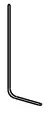
- Screwdriver
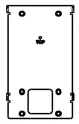
- Bracket

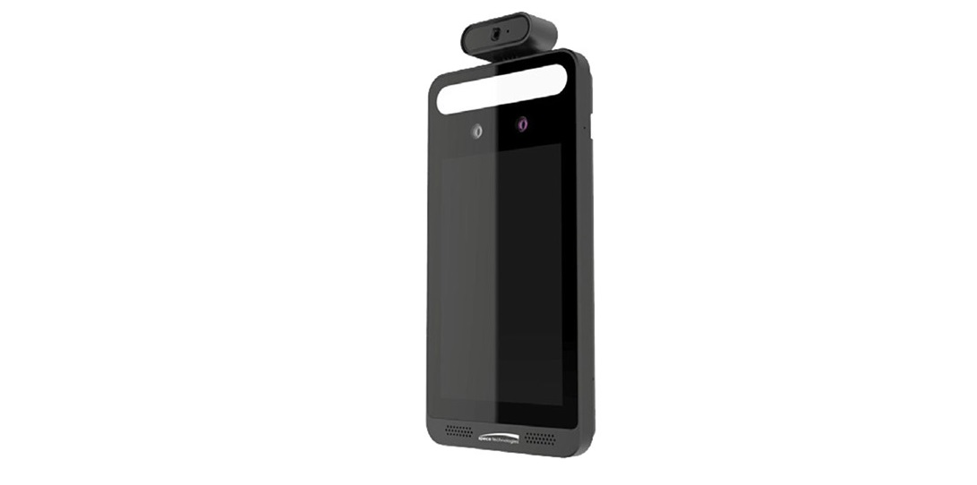
Overview
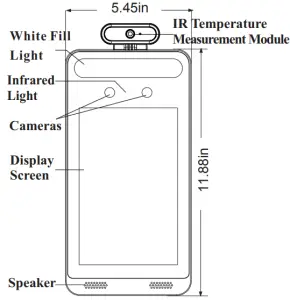
Front
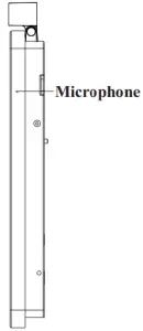
Left
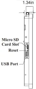
Right
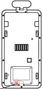
Back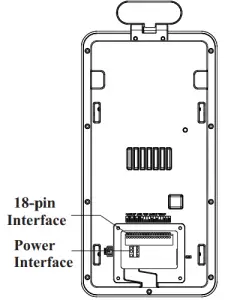
Cable Connection
18-pin Interface
| 1 | 2 | 3 | 4 | 5 | 6 | 7 | 8 | 9 | 10 | 11 | 12 | 13 | 14 | 15 | 16 | 17 |
18 |
| NO2 | COM2 | NO1 | COM1 | NO3 | COM3 | NC3 | D+ | D- | IN1 | GND | IN2 | GND | D0 | D1 | GND | BUT | GND |
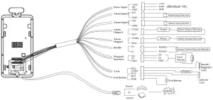
Note:
- The wiegand terminal here is a wiegand input terminal. If you want to connect to an access controller, you shall set the Wiegand direction to “Output”.
- The RS 485 interface of this device supports security module access. Once the security module is enabled, the exit button and lock control will be invalid.
Installation
Ambient Illumination RequirementMake sure faces can be captured clearly. Avoid direct sunlight and backlight . The device should be at least 6.5ft away from the light, and at least 10ft away from the window or door.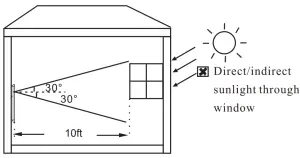
Installation
- Paste the drill template onto the wall and then drill the holes according to it.
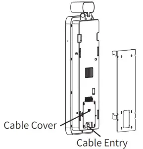
- Install the gang box on the wall. Then use two screws to secure the bracket on the gang box. Secure the bracket onto the wall with 4 screws.
- Route and connect the cables and then install the cable cover (if applicable).
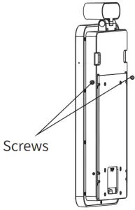
- Hang the device onto the bracket hook and then tighten the screws.
Pole Mounting
Note: Pole mounting bracket is not supplied with the device by default.
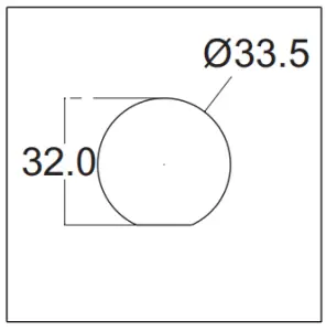
- Cut the hole on the installation surface according to the drill template.
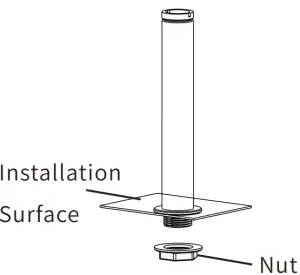
- Install the pole and then tighten the nut.
- Install the pole and then tighten the nut.
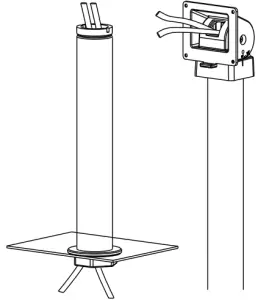
- Tighten the screw with a L-shaped screwdriver.
- Connect the cables.
- Install the rubber plug.
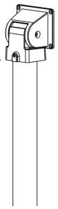
- Fix the device and the bracket with four screws.
- Loosen the screws to adjust the angle of the device.
Height Requirement
- The recommended installation height (H) is from 4.25ft to 4.75ft which can cover human height of 4.6ft ~ 6.3ft in the detection area. It can be adjusted according to the actual scene.
- The best temperature measuring distance ranges from 1ft to 1.3ft.
- The best face recognition distance ranges from 1.6ft to 3.2ft.
Network Connection
- Make sure that the device and the PC are well connected via LAN
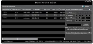
- Find the Speco Blue Scanner from the website URL and then install it in the computer. After that, run the s canner as shown below.
- The device is defaulted to obtain its IP address automatically from the DHCP server. Click the information of the camera listed in the above table to show the network information on the right hand.If desired, you can modify the IP address and gateway of the camera and make sure its network address is in the same local network segment as that of the computer.After modification, please enter the password of the administrator and click “Modify” button to modify the settings. The default password of the administrator is “1234”
- Double-click the camera listed in the s canner or manually enter the IP address in the address bar of the web browser to connect to the device. Then follow directions to download and install the plugin.
- Enter the username and password in the login interface. The default username is admin; the default password is 1234.
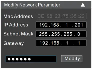 After modification, please enter the password of the administrator and click “Modify” button to modify the settings.
[xyz-ips snippet=”download-snippet”]