
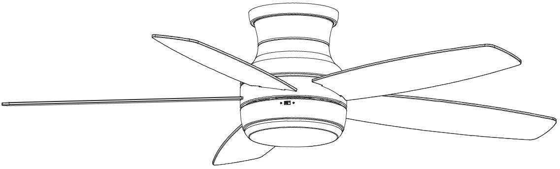
 USE AND CARE GUIDEASHBY PARK 52-INCH CEILING FAN
 Item #1004 065 046Model #59252UL Model #52-PORT
Questions, problems, missing parts? Before returning to the store, call Home Decorators Collection Customer Service8 a.m. – 7 p.m., EST, Monday-Friday, 9 a.m. – 6 p.m., EST, Saturday.1-800-986-3460HOMEDEPOT.COM/HOMEDECORATORS

THANK YOUWe appreciate the trust and confidence you have placed in the Home Decorators Collection through the purchase of this ceiling fan. We strive to continually create quality products designed to enhance your home. Visit us online to see our full line of products available for your home improvement needs. Thank you for choosing Home Decorators Collection!
Safety Information
READ AND SAVE THESE INSTRUCTIONS.
- To reduce the risk of electric shock, ensure the electricity has been turned off at the circuit breaker or fuse box before you begin.
- All wiring must be in accordance with the National Electrical Code ANSI/NFPA 70-1999 and local electrical codes. Electrical installation should be performed by a qualified licensed electrician.
- The outlet box and support structure must be securely mounted and capable of reliably supporting 35 lbs. (15.9 kg). Use only UL Listed outlet boxes marked “Acceptable for Fan Support of 35 lbs. (15.9 kg) or less.”
- The fan must be mounted with a minimum of 7 ft (2.1 m) clearance from the trailing edge of the blades to the floor.
- Do not operate the reversing switch while the fan blades are in motion. You must turn the fan off and stop the blades before you reverse the blade direction.
- Do not place objects in the path of the blades.
- To avoid personal injury or damage to the fan and other items, use caution when working around or cleaning the fan.
- Electrical diagrams are for reference only. Light kits that are not packed with the fan must be UL listed and marked suitable for use with the model fan you are installing. Switches must be UL General Use Switches. Refer to the instructions packaged with the light kits and switches for proper assembly.
- After making electrical connections, spliced conductors should be turned upward and pushed carefully up into the outlet box. The wires should be spread apart with the grounded conductor and the equipment-grounding conductor on one side of the outlet box.
- All setscrews must be checked and retightened where necessary before installation.
 WARNING: To reduce the risk of personal injury, do not bend the blade brackets (also referred to as flanges) during assembly or after installation. Do not insert objects in the path of the blades.WARNING: To reduce the risk of fire, electric shock, or personal injury, mount to outlet box marked “Acceptable for fan support of 35 lbs. (15.9 kg) or less”, and use screws provided with the outlet box.WARNING: To avoid possible electrical shock, turn the electricity off at the main fuse box before wiring. If you feel you do not have enough electrical wiring knowledge or experience, contact a licensed electrician.WARNING: Electrical diagrams are for reference only. Optional use of any light kit shall be UL-listed and marked suitable for use with this fan.WARNING: To reduce the risk of fire or electric shock, this fan should only be used with fan speed control part no. AP-8RDL, manufactured by Dawnsun Electronic Co., LTD.
 CAUTION: To reduce the risk of personal injury, use only the screws provided with the outlet box.CAUTION: To avoid personal injury or damage to the fan and other items, se caution when working around or cleaning the fan.
Warranty
The supplier warrants the fan motor to be free from defects in workmanship and material present at the time of shipment from the factory for a lifetime after the date of purchase by the original purchaser. The supplier also warrants that all other fan parts, excluding any glass or acrylic blades, be free from defects in workmanship and material at the time of shipment from the factory for a period of two years after the date of purchase by the original purchaser. We agree to correct such defects without charge or at our option replace them with a comparable or superior model if the product is returned. To obtain warranty service, you must present a copy of the receipt as proof of purchase. All costs of removing and reinstalling the product are your responsibility. Damage to any part, such as by accident, misuse, improper installation, or by affixing any accessories, is not covered by this warranty. Because of varying climatic conditions, this warranty does not cover any changes in brass finish, including rusting, pitting, corroding, tarnishing, or peeling. Brass finishes of this type give their longest useful life when protected from varying weather conditions. A certain amount of “wobble” is normal and should not be considered a defect. Servicing performed by unauthorized persons shall render the warranty invalid. There is no other express warranty. Home Decorators Collection hereby disclaims any and all warranties, including but not limited to those of merchantability and fitness for a particular purpose to the extent permitted by law. The duration of any implied warranty, which cannot be disclaimed, is limited to the time period as specified in the express warranty. Some states do not allow a limitation on how long an implied warranty lasts, so the above limitation may not apply to you. The retailer shall not be liable for incidental, consequential, or special damages arising out of or in connection with product use or performance except as may otherwise be accorded by law. Some states do not allow the exclusion of incidental or consequential damages, so the above exclusion or limitation may not apply to you. This warranty gives specific legal rights, and you may also have other rights that vary from state to state. This warranty supersedes all prior warranties. Shipping costs for any return of the product as part of a claim on the warranty must be paid by the customer.Contact the Customer Service Team at 1-800-986-3460 or visit www.HomeDepot.com/homedecorators.
Pre-Installation
SPECIFICATIONS
| Size | Speed | Volts | Amps | Watts | RPM | CFM | NetWeight | GrossWeight | Cu. Ft. |
| 52 In. | Low | 120 | 0.26 | 15 | 85 | 2185 | 19.40 Ihs 19.(8.8 kg( | 22.05 Ihs(10 kg) | 2.134 cu.ft. |
| Medium | 0.38 | 31 | 130 | 3324 | |||||
| High | 0.53 | 63 | 185 | 4881 |

 NOTE: These are approximate measures. They do not include the amps and wattage used by the light kit.
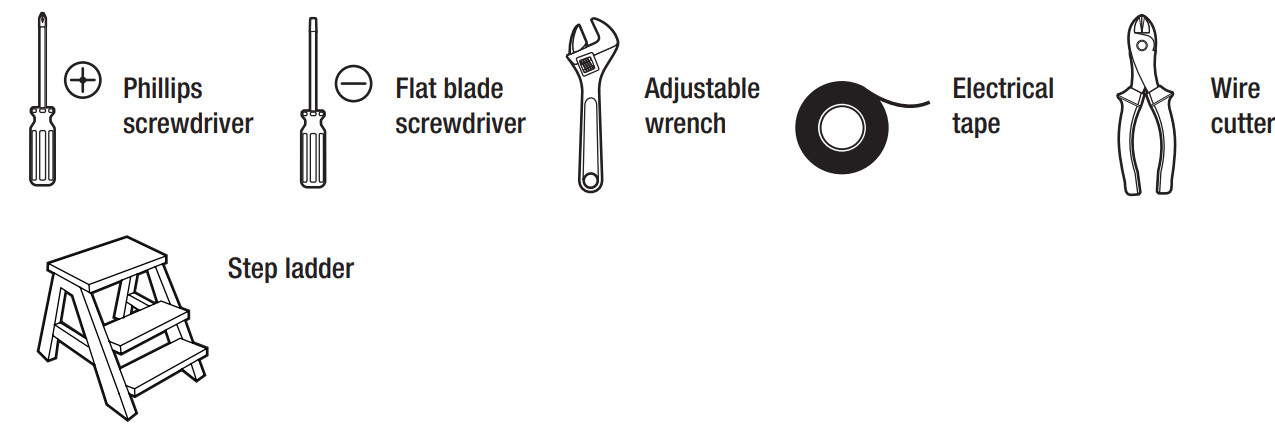
TOOLS REQUIRED
HARDWARE INCLUDEDNOTE: Hardware not shown to actual size.
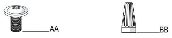
| Part | Description | Quantity |
| AA | Blade attachment screws | 16 |
| BB | Plastic wire connector | 3 |
PACKAGE CONTENTS

| Part | Description | Quantity |
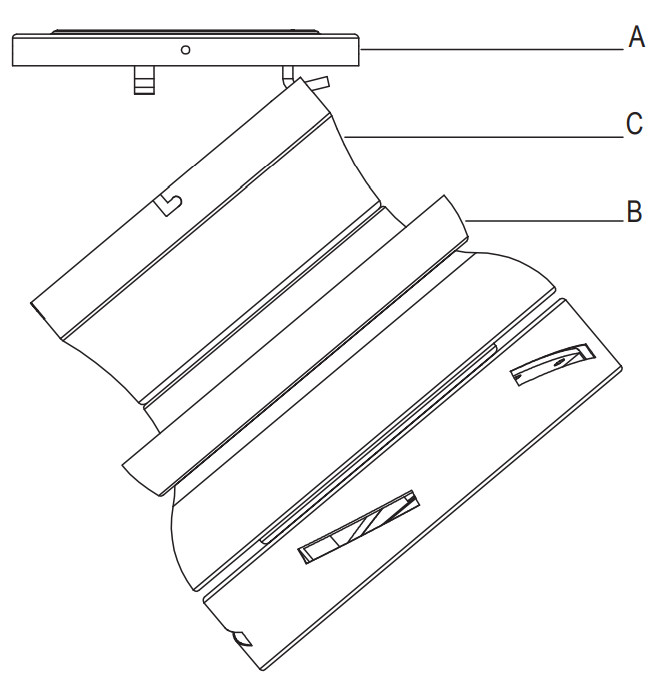
| A | Mounting plate | 1 |
| B | Trim ring | 1 |
| C | Fan-motor assembly | 1 |
| D | Blade | 5 |
| Part | Description | Quantity |
| E | Light kit fitter assembly | 1 |
| F | Light kit pan | 1 |
| G | Glass bowl | 1 |
| H | Receiver | 1 |
| I | Remote control (battery included) | 1 |
 IMPORTANT: This product and/or components are governed by one or more of the following U.S. Patents:5,947,436; 5,988,580; 6,010,110; 6,046,416; 6,210,117 and other patents pending.
Installation
MOUNTING OPTIONSWARNING: To reduce the risk of fire, electric shock or personal injury, mount to outlet box marked “Acceptable for fan support of 35 lbs. (15.9 kg) or less”, and use screws provided with the outlet box. An outlet box commonly used for the support of lighting fixtures may not be acceptable for fan support and may need to be replaced. If in doubt, consult a qualified electrician.If your ceiling fan does not have an existing UL-listed mounting box, then install one using the following instructions:
- Disconnect the power by removing the fuses or turning off the circuit breakers.
- Secure the outlet box directly to the building structure. Use the appropriate fasteners and materials. The outlet box and support structure must be securely mounted and capable of reliably supporting 35 lbs. (15.9 kg). Use only UL Listed outlet boxes marked “Acceptable for Fan Support of 35 lbs. (15.9 kg) or less.” Do not use a plastic outlet box.
The illustrations below show two different ways to mount the outlet box.
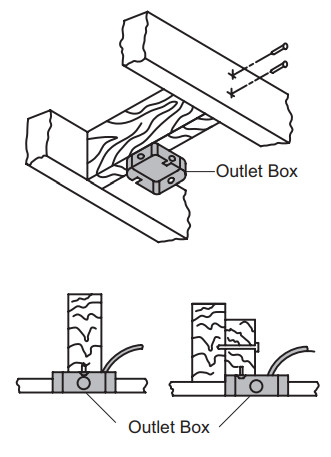
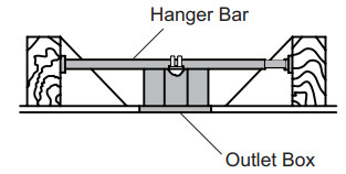
To hang your fan where there is an existing fixture but no ceiling joist, you may need an installation hanger bar as shown above (available at any Home Depot store).
Assembly – Hanging the Fan
Attaching the fan to the electrical boxWARNING: To avoid possible electrical shock, urn the electricity off at the main fuse box before wiring. If you feel you do not have enough electrical wiring knowledge or experience, contact a licensed electrician.NOTE: For better fan performance, make sure the mounting plate is level. Additional washers (FF) (not included) may be needed to insert between the outlet box and mounting plate.
- Turn the power off.
- Loosen the two mounting screws (GG) supplied with the outlet box, but do not remove the screws.
- Securely attach the mounting plate (A) to the outlet box by sliding the mounting plate (A) over the two mounting screws (GG) supplied with the outlet box. Pull the 120-volt supply wires (the black, white, and ground wires) out of the outlet box (EE) and through the hole in the mounting plate (A) and lay them to the side.

Hanging the fan-motor assembly
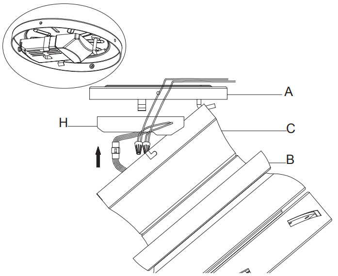
- Attach the trim ring (B) to the fan motor assembly (C) from the opening of the motor housing. Make sure the slots of trim ring (B) are on top.
- Carefully lift the fan-motor assembly (C) and hang the fan motor assembly (C) on the hook of the mounting plate (A)by utilizing one of the holes at the outer rim of the motor housing so that it is securely suspended. Then connect the wiring to your fan according to step 4 “Making the Electrical Connections”.
Setting the code on the remote control and receiver
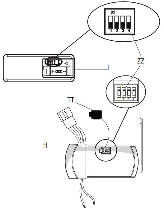
NOTE: The frequencies on your receiver and hand unit have been preset at the factory. Before installing the receiver, make sure the dip switches on the receiver and hand unit are set to the same frequency. The dip switches on the hand unit are located inside the battery compartment.NOTE: The battery will weaken with age and should be replaced before leaking takes place as this will damage the hand unit. Dispose of used battery properly and keep the battery out of the reach of children.
- Remove the remote control (I) battery cover by pressing firmly on the arrow and sliding the cover off.
- Slide the dip switches (ZZ) to your choice of either up or down. The factory setting is up.
- Slide the dip switches (ZZ) on the receiver (H) to the same position asset on the remote control (I).
- Install the 23A 12V battery (included).
- Replace the battery cover on the remote control (I).
- Insert the silicone rubber stopper (TT) into the hole on the receiver (H) to cover the dip switches.
Making the electrical connectionWARNING: Each wire nut supplied with this fan is designed to accept up to one 12-gauge house wire and two wires from the fan. If you have larger than 12-gauge house wiring or more than one house wire to connect to the fan wiring, consult an electrician for the proper size wire nuts to use.IMPORTANT: Use the plastic wire connectors (BB) supplied with your fan. Secure the connectors with electrical tape and ensure there are no loose strands or connections.
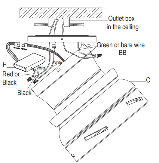
- Spread the wires apart so that the green and whites are on one side of the outlet box and the black wire is on the other side.
- Connect the green fan wires to the household ground wire (this may be a green or bare wire) using a wire connecting nut (BB).
- Connect the receiver (H) red or black wire to the household black (hot) wire using a wire connecting nut (BB).
- Connect the receiver (H) white wire to the household white (neutral) wire using a wire connecting nut (BB).
- Secure each wire connecting nut using electrical tape.
- Wire the receiver (H) to the fan wires by connecting the molded adaptor plug from the receiver (H) with the molded adaptor of the fan motor assembly (C) together.
Installing the receiverWARNING: To reduce the risk of fire or electrical shock, remember to disconnect power. The electrical wiring must meet all local and national electrical code requirements. The electrical source and fan must be 110/120 volt, 60HZ. Do not use this product in conjunction with any variable wall control. Incorrect wire connections can damage this receiver.CAUTION: If other fan wires are different colors, have this unit installed by a licensed electrician.CAUTION: Do not install the receiver (H) in a damp location or immerse in water (For indoor use only). Do not pull on or cut the receiver leads shorter. Do not drop or bump the unit.
- Push the receiver (H) into the bracket on the mounting plate (A) (as shown, flat side towards the ceiling).
 Installing the motor assembly
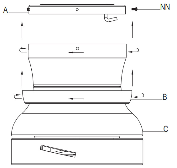
- Remove two of the four screws (located diagonally from each other) (NN) from the top of the mounting plate (A) and loosen the other two screws (NN).
- Align the two key slots in the top of the fan motor assembly (C) with the two loosened screws (NN) on the mounting plate (A). Push the fan motor assembly (C) up and turn it clockwise to lock in the mounting plate (A). Tighten the two screws.
- Install the two screws that were removed at the beginning of this step into the remaining two holes and tighten the four screws firmly.
- Install the trim ring (B) by aligning the ring’s slots with the screws on the mounting plate (A). Rotate the ring clockwise to lock in place.

Assembly – Attaching the Blades
Attaching the blades
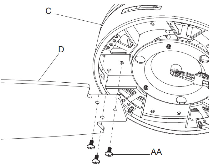
- Attach a blade (D) to the fan motor assembly (C) by inserting the blade (D) into slots in the side of the fan motor assembly (C) and aligning the three screws holes in the blade with the holes in the center flywheel and secure with screws (AA).
- Make sure all the screws are firmly tightened.
- Repeat these steps for the remaining blades.
Assembly – Attaching the Light Kit
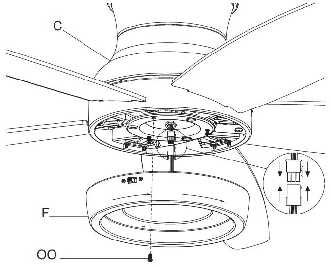
Installing the light kit panIMPORTANT: It is critical to attach the light kit pan using a quick connector. The fan will not operate unless the light kit pan is connected to the fan.
- Remove one screw (OO) from the black bracket below the fan motor assembly (C), and loosen but do not remove the other two screws.
- Connect the 9-pin plug exiting the bottom of the fan motor assembly (C) to the 9-pin plug from the light kit pan (F). Be sure the plug connections snap together completely.
- Push the light kit pan (F) up to the fan motor assembly (C) so that the two loosened screw heads fit into the keyhole slots. Turn the light kit pan (F) clockwise.
- Re-install the screw (OO) that was removed in step 1.
- Make sure all the screws are firmly tightened.
Attaching the light kit fitter assemblyCAUTION: To reduce the risk of electric shock, disconnect the electrical supply circuit to the fan before installing the light kit.
- Remove one screw (PP) from the light kit pan (F) and loosen but do not remove the other two screws.
- Connect the wires from the light kit fitter assembly (E) to the ires from the light kit pan (F) by connecting the molded adaptor plugs together. Carefully tuck all wires and splices into the switch cup.
- Push the light kit fitter assembly (E) up to the light kit pan (F) so that the two loosened screw heads fit into the keyhole slots. Turn the light kit fitter assembly (E) clockwise.
- Re-install the screw (PP) that was removed in step 1.
- Make sure all the screws are firmly tightened.

Installing the glass bowlWARNING: Allow the glass bowl to cool completely before removing it.CAUTION: Make sure the power is off before attaching or removing the glass bowl.
- Place the glass bowl (G) into the light kit pan (F), aligning the three flat areas on the top flange of the glass bowl (G) with the raised dimples in the light kit pan.
- Turn the glass bowl (G) clockwise until it stops.

Operation
NOTE: Wait for the fan to stop before reversing the direction of the blade rotation.Remote controlYour fan is equipped with a remote control to operate the speed and lights for your new ceiling fan.Speed setting for warm or cool weather depends on factors such as the room size, ceiling height, number of fans, and so on.The fan is shipped from the factory with the reversing switch (YY) positioned to circulate air downward. If the airflow is desired in the opposite direction, turn your fan off and wait for the blades to stop turning, then slide the reversing switch (located on the light kit pan) to the opposite position, and turn the fan on again. The fan blades will turn in the opposite direction and reverse airflow.Warm weather – (Forward) A downward airflow creates a cooling effect. This allows you to set your air conditioner in a warmer setting without affecting your comfort.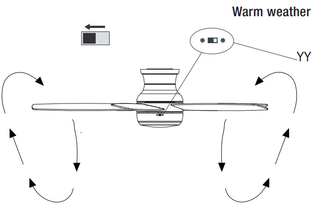 Cool-weather – (Reverse) An upward airflow moves warm air off of the ceiling. This allows you to set your heating unit in a cooler setting without affecting your comfort.
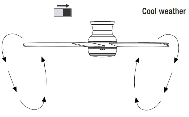
Operating your fan and remote control
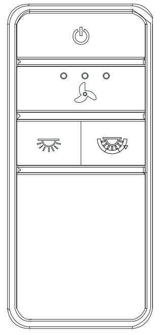
![]() Power ON/OFF: Press and release the power button to turn the fan and light on or off.
Power ON/OFF: Press and release the power button to turn the fan and light on or off. Fan speed: LEDs on the fan speed button will illuminate the corresponding speed.Press and release 1 time: turns the fan on high speed.Press and release 2 times: turns the fan on medium speed.Press and release 3 times: turns the fan on low speed.Press and release 4 times: turns the fan off.
![]() Light ON/OFFPress and release the button to turn the light on or off.Press and hold the button to activate the dimmer function.
Light ON/OFFPress and release the button to turn the light on or off.Press and hold the button to activate the dimmer function.![]() Correlated Color Temperature (CCT) changingNOTE: The default temperature of the ceiling fan light is 3000k (Soft White).Push and release the button to cycle through the three color temperature options.Option 1: 2700K (Warm White).Option 2: 3000K (Soft White).Option 3: 5000K (Daylight).
Correlated Color Temperature (CCT) changingNOTE: The default temperature of the ceiling fan light is 3000k (Soft White).Push and release the button to cycle through the three color temperature options.Option 1: 2700K (Warm White).Option 2: 3000K (Soft White).Option 3: 5000K (Daylight).
Care and Cleaning
WARNING: Make sure the power is off before cleaning your fan.
- Because of the fan’s natural movement, some connections may become loose. Check the support connections, brackets, and blade attachments twice a year. Make sure they are secure. It is not necessary to remove the fan from the ceiling.
- Clean your fan periodically to help maintain its new appearance over the years. Do not use water when cleaning, as this could damage the motor, or the wood, or possibly cause an electrical shock. Use only a soft brush or lint-free cloth to avoid scratching the finish. The plating is sealed with a lacquer to minimize discoloration or tarnishing.
- You can apply a light coat of furniture polish to the wood for additional protection and enhanced beauty. Cover small scratches with a light application of shoe polish.
- You do not need to oil your fan. The motor has permanently lubricated sealed ball bearings.
Troubleshooting
| Problem | Solution |
| The fan will not start. |
|
| The fan is noisy. |
|
| The fan wobbles. |
|
This equipment has been tested and found to comply with the limits for a Class B digital device, pursuant to Part 15 of the FCC Rules. These limits are designed to provide reasonable protection against harmful interference in a residential installation. This equipment generates, uses and can radiate radio frequency energy and, if not installed and used in accordance with the instructions, may cause harmful interference to radio communications. However, there is no guarantee that interference will not occur in a particular installation. If this equipment does cause harmful interference to radio or television reception, which can be determined by turning the equipment off and on, the user is encouraged to try to correct the interference by one or more of the following measures:–Reorient or relocate the receiving antenna.–Increase the separation between the equipment and receiver.–Connect the equipment into an outlet on a circuit different from that to which the receiver is connected.–Consult the dealer or an experienced radio/TV technician for help.CAUTION:Any changes or modifications not expressly approved by the grantee of this device could void the user’s authority to operate the equipment.This device complies with Part 15 of the FCC Rules. Operation is subject to the following two conditions: (1) This device may not cause harmful interference, and (2) this device must accept any interference received, including interference that may cause undesired operation.
Questions, problems, missing parts? Before returning to the store,call Home Decorators Collection Customer Service8 a.m. – 7 p.m., EST, Monday-Friday, 9 a.m. – 6 p.m., EST, Saturday1-800-986-3460HOMEDEPOT.COM/HOMEDECORATORSRetain this manual for future use.
References
[xyz-ips snippet=”download-snippet”]