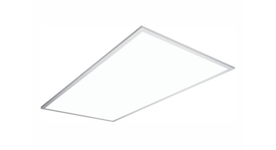
![]() USE AND CARE GUIDELED FLAT PANEL FIXTURE
USE AND CARE GUIDELED FLAT PANEL FIXTURE
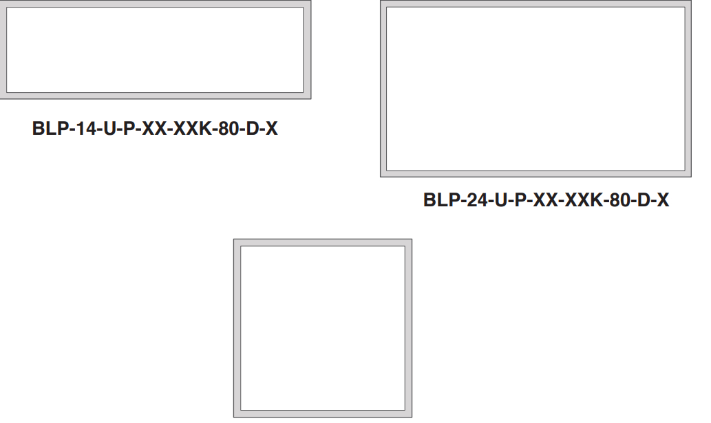 BLP-22-U-P-XX-XXK-80-D-X
Questions, problems, missing parts? Before returning to the store,call Commercial Electric Customer Service8 a.m. – 7 p.m., EST, Monday – Friday, 9 a.m. – 6 p.m., EST, Saturday1-844-584-3776HOMEDEPOT.COM
THANK YOU We appreciate the trust and confidence you have placed in Commercial Electric through the purchase of this LED Flat Panel Fixture. We strive to continually create quality products designed to enhance your home. Visit us online to see our full line of products available for your home improvement needs. Thank you for choosing Commercial Electric!
Safety Information
For your safety, always remember to:
- Turn off the power supply at the fuse or circuit breaker box
- before you install the fixture.
- Ground the fixture to avoid potential electric shocks and to ensure reliable starting.
- Double-check all connections to be sure they are tight and correct.
- Wear rubber-soled shoes and work on a sturdy wooden ladder.
- Account for small parts and destroy packing material, as these may be hazardous to children.
This fixture is designed for use in a circuit protected by a fuse or circuit breaker. It is also designed to be installed in accordance with local electrical codes. If you are unsure about your wiring, consult a qualified electrician or local electrical inspector, and check your local electrical code.
Supplier’s Declaration of Conformity 47 CFR § 2.1077 Compliance Information
Unique Identifier: See detail on specification in user manual with markedResponsible Party – U.S. Contact Information
ERAN FINANCIAL SERVICES LLC3500 NW Boca Raton Blvd, Suite 717, Jupiter,Florida, 33427, United StatesTelephone Number: 845-264-4855
![]() WARNING: RISK OF SHOCK. House electric current can cause painful shock or serious injury unless handled properly.
WARNING: RISK OF SHOCK. House electric current can cause painful shock or serious injury unless handled properly.
![]()
CAUTION: Turn off the main power at the circuit breaker before installing the fixture, in order to prevent possible shock.
NOTICE: All electrical connections must be in accordance with local and National Electrical Code (N.E.C.) standards. If you are unfamiliar with proper electrical wiring connections obtain the services of a qualified electrician.Remove the fixture and the mounting package from the box and make sure that no parts are missing by referencing the illustrations on the installation instructions.
FCC STATEMENTThis device complies with Part 15 of the FCC Rules. Operation is subject to the following two conditions: (1) this device may not cause harmful interference, and (2) this device must accept any interference received, including interference that may cause undesired operation. Note: This equipment has been tested and found to comply with the limits for a Class B digital device, pursuant to part 15 of the FCC Rules. These limits are designed to provide reasonable protection against harmful interference in a residential installation. This equipment generates, uses, and can radiate radio frequency energy and, if not installed and used in accordance with the instructions, may cause harmful interference to radio communications. However, there is no guarantee that interference will not occur in a particular installation. If this equipment does cause harmful interference to radio or television reception, which can be determined by turning the equipment off and on, the user is encouraged to try to correct the interference by one or more of the following measures: Reorient or relocate the receiving antenna. Increase the separation between the equipment and receiver. Connect the equipment into an outlet on a circuit different from that to which the receiver is connected. Consult the dealer or an experienced radio/TV technician for help. Any changes or modifications not expressly approved by the manufacture could void the user’s authority to operate the equipment.
Warranty
LIMITED WARRANTYThis product is warranted to be free from defects in workmanship and materials for up to 5 years from date of purchase. If it fails to do so, please contact the Customer Service Team at 1-844-584-3776 or visit www.HomeDepot.com.
Pre-Installation
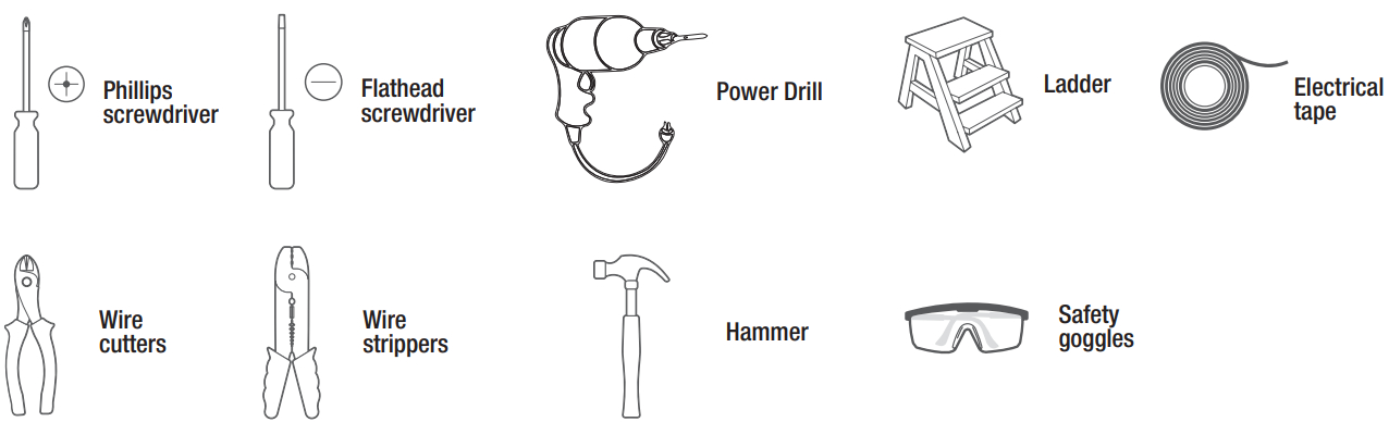
TOOLS REQUIRED
HARDWARE INCLUDED
![]() NOTE: Hardware not shown to actual size.
NOTE: Hardware not shown to actual size.
![]()
| Part | Description | Quantity |
| EE | Wire Nuts | 5 |
Before You Begin
- Turn off the electricity at the circuit breaker or fuse box.
- Choose your installation option:• Installation Option 1 – Recessed Mount• Installation Option 2 – Surface Mount Kit (Sold Separately)• Installation Option 3 – Pendant/Suspension Mount Kit (Sold Separately)
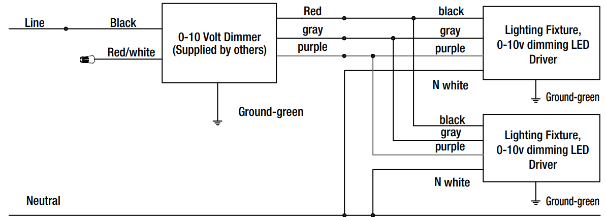
0-10V Dimming Schematic
REMARK: Please reference the manufacturer of the dimmer wiring diagrams for correct wiring of 0-10 Volt Dimmer.
![]() WARNING: Refer to Local and National Electrical codes for correctly sizing wire gauges and making the proper electrical connections and ground connections to prevent electrical shock and risk of fire. Installation requires knowledge of luminaires and electrical systems. If not qualified, do not attempt installation. Contact a qualified licensed electrician, to ensure the wiring is correct and in compliance with local codes.
WARNING: Refer to Local and National Electrical codes for correctly sizing wire gauges and making the proper electrical connections and ground connections to prevent electrical shock and risk of fire. Installation requires knowledge of luminaires and electrical systems. If not qualified, do not attempt installation. Contact a qualified licensed electrician, to ensure the wiring is correct and in compliance with local codes.
Specification
| Model No. | UPC | Volts (V) | Frequency (HZ) | Watts (W) | Current (mA) | Unique Identifier |
| BLP-24-U-P-50-50K-80-D-1 | 850014987374 | 120V-277V | 50/60 | 50 | 0.6 | |
|
BLP-24-U-P-50-40K-80-D-1 |
850014987367 |
120V-277V |
50/60 |
50 |
0.6 |
|
|
BLP-24-U-P-50-35K-80-D-1 |
850014987350 |
120V-277V |
50/60 |
50 |
0.6 |
|
|
BLP-24-U-P-40-40K-80-D-1 |
850014987343 | 120V-277V | 50/60 | 40 | 0.5 | |
| BLP-24-U-P-40-35K-80-D-1 | 850014987336 | 120V-277V | 50/60 | 40 | 0.5 | |
|
BLP-22-U-P-36-50K-80-D-1 |
850014987329 |
120V-277V |
50/60 | 36 | 0.4 | |
| BLP-22-U-P-36-40K-80-D-1 | 850014987312 | 120V-277V | 50/60 | 36 | 0.4 | |
| BLP-22-U-P-36-35K-80-D-1 | 850014987305 | 120V-277V | 50/60 | 36 | 0.4 | |
|
BLP-22-U-P-30-40K-80-D-1 |
850014987299 | 120V-277V | 50/60 | 30 | 0.35 | |
| BLP-14-U-P-30-40K-80-D-1 | 850014987275 | 120V-277V | 50/60 | 30 | 0.35 | |
|
BLP-14-U-P-30-35K-80-D-1 |
850014987268 |
120V-277V |
50/60 |
30 |
0.35 |
|
|
BLP-22-U-P-30-35K-80-D-1 |
850014987282 |
120V-277V |
50/60 |
30 |
0.35 |
|
| BLP-24-U-P-50-50K-80-D-2 | 850014987497 | 120V-277V | 50/60 | 50 | 0.6 | |
|
BLP-24-U-P-50-40K-80-D-2 |
850014987480 |
120V-277V |
50/60 |
50 |
0.6 | |
|
BLP-24-U-P-50-35K-80-D-2 |
850014987473 |
120V-277V |
50/60 |
50 |
0.6 |
|
| BLP-24-U-P-40-40K-80-D-2 | 850014987466 | 120V-277V | 50/60 | 40 | 0.5 | |
| BLP-24-U-P-40-35K-80-D-2 | 850014987459 | 120V-277V | 50/60 | 40 | 0.5 | |
|
BLP-22-U-P-36-50K-80-D-2 |
850014987442 |
120V-277V | 50/60 | 36 | 0.4 | |
|
BLP-22-U-P-36-40K-80-D-2 |
850014987435 | 120V-277V | 50/60 | 36 | 0.4 | |
|
BLP-22-U-P-36-35K-80-D-2 |
850014987428 |
120V-277V |
50/60 |
36 | 0.4 | |
| BLP-22-U-P-30-40K-80-D-2 | 850014987411 | 120V-277V | 50/60 | 30 | 0.35 | |
|
BLP-22-U-P-30-35K-80-D-2 |
850014987404 |
120V-277V |
50/60 |
30 |
0.35 |
|
|
BLP-14-U-P-30-40K-80-D-2 |
850014987398 |
120V-277V |
50/60 |
30 |
0.35 |
|
|
BLP-14-U-P-30-35K-80-D-2 |
850014987381 |
120V-277V |
50/60 |
30 |
0.35 |
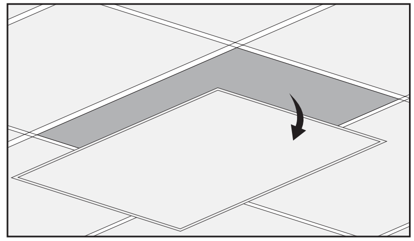
Recessed Installation
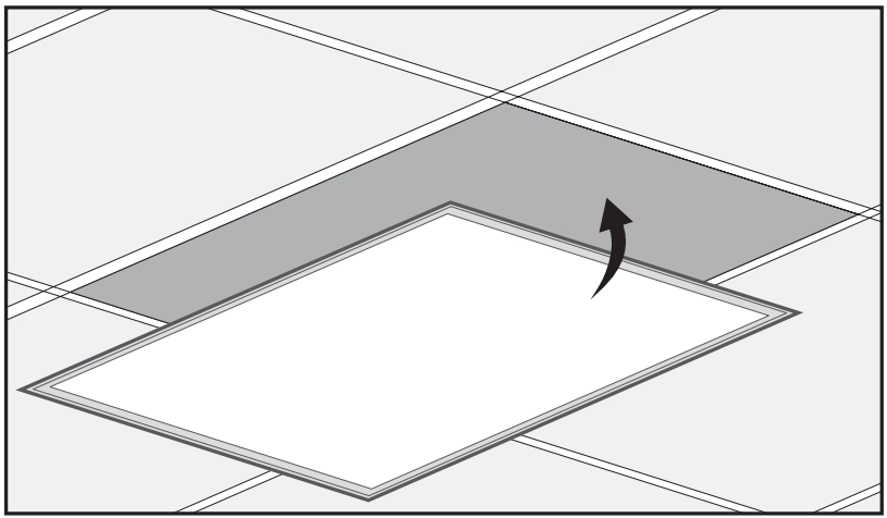
1 Removing the ceiling panela. Remove the plasterboard panel from the ceiling.
2 Connecting the wiresa. Lift the fixture to the ceiling.b. Follow the steps in the Making the Electrical Connections section of this manual.
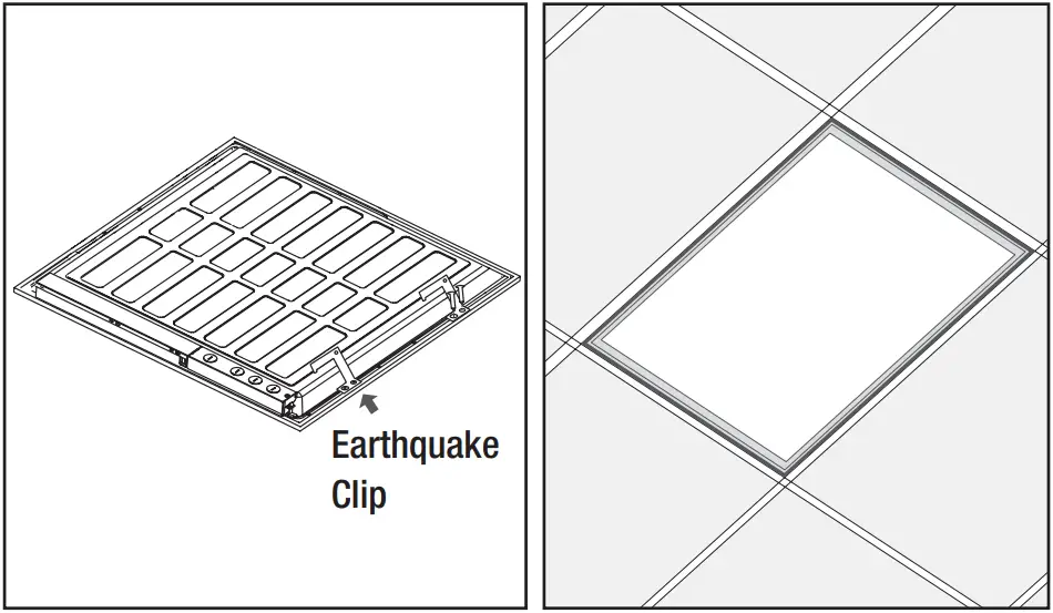
3 Completing the installationa. Slide the fixture into place in the ceiling.b. Restore power to the fixture.
Making the Electrical Connections
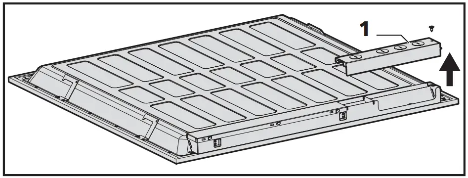
1 Open the junction box a. Unscrew and remove the junction box cover (1) from the fixture.
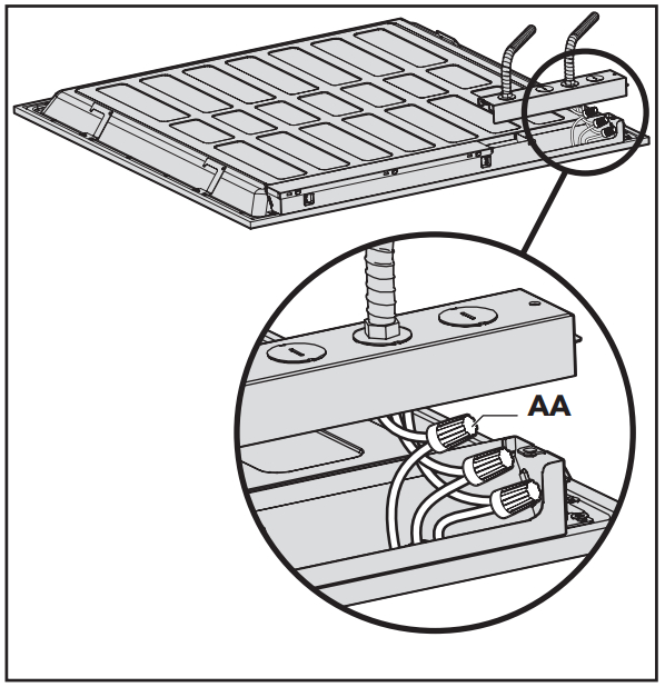
2 Connect the supply wiresa. Connect the green ground wire from the fixture to the supply ground wire.b. Connect the white wire from the fixture to the supply white wire (neutral wire).c. Connect the black wire from the fixture to the supply black wire (live wire).d. Secure the three connections using three of the supplied wire nuts (AA).e. Wrap the three wire connections with electrical tape for a more secure connection (electrical tape not included).
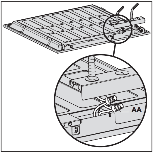
3 Connect the dimming wiresa. Connect the purple wire from the fixture to the purple (DIM+) supply wire.b. Connect the gray wire from the fixture to the gray (DIM-) supply wire.c. Secure the two connections using the remaining two supplied wire nuts (AA).d. Wrap the two-wire connections with electrical tape for a more secure connection (electrical type not included).
4 Reinstall the junction box covera. Position the wires back inside the junction box.b. Reinstall the junction box cover (1).

![]() Questions, problems, missing parts? Before returning to the store,call Commercial Electric Customer Service8 a.m. – 7 p.m., EST, Monday – Friday, 9 a.m. – 6 p.m., EST, Saturday1-844-584-3776HOMEDEPOT.COM
Questions, problems, missing parts? Before returning to the store,call Commercial Electric Customer Service8 a.m. – 7 p.m., EST, Monday – Friday, 9 a.m. – 6 p.m., EST, Saturday1-844-584-3776HOMEDEPOT.COM
References
[xyz-ips snippet=”download-snippet”]