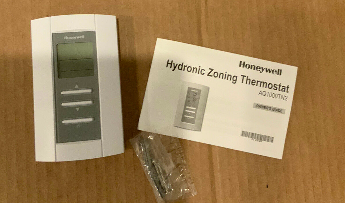
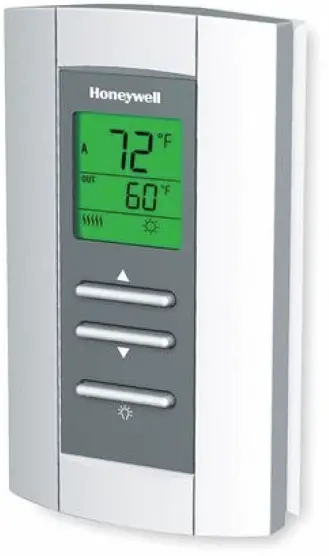
Honeywell Home AQ1000TN2 Hydronic Zoning Thermostat
Need Help?
For assistance with this product please visit resideo.com or call Customer Care toll-free at 1-800-468-1502.Read and save these instructions.The product should not be disposed of with other household waste. Check for the nearest authorized collection centers or authorized recyclers. The correct disposal of end-of-life equipment will help prevent potential negative consequences for the environment and human health.See https://customer.resideo.com/en-US/support/residential/codes-and-standards/FCC15105/Pages/default.aspx for additional FCC information for this product.
ABOUT YOUR NEW THERMOSTAT
Resideo’s AQ1000TN2 hydronic zoning thermostat can be used to control theambient air temperature or floor temperature. You can choose among the following temperature control modes (see page 11):
- A mode: Controls and displays the ambient air temperature
- F mode: Controls and displays the floor temperature using an external temperature sensor
- AF mode: Controls and displays the ambient air temperature, maintains the floor temperature within desired limits using an external temperature sensor
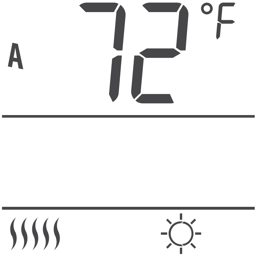
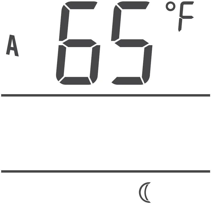
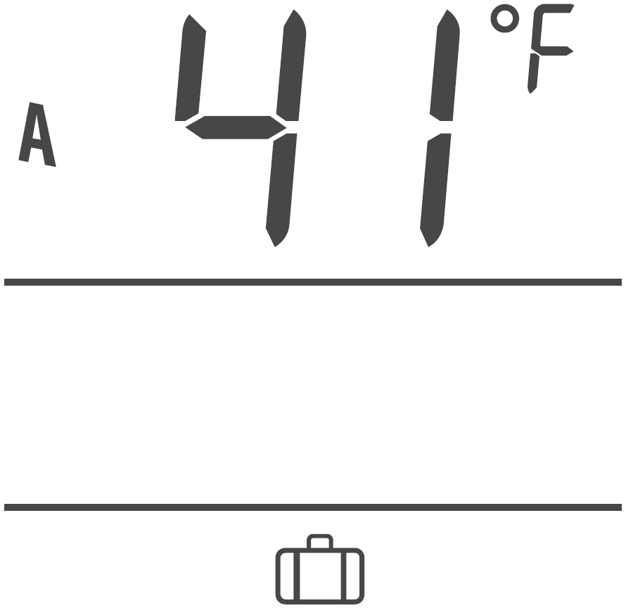
SCREEN DISPLAY
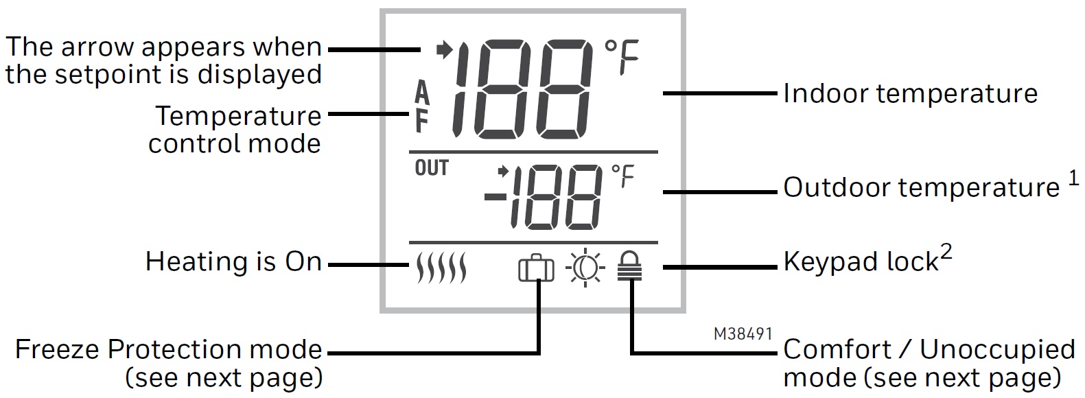
1. The outdoor temperature will be displayed only if the data is available.2. This icon appears to indicate that the thermostat settings cannot be modified as the hydronic zoning controller has locked the keypad. The backlight button and the ▲▼ buttons can still be used to activate the backlight and to display the setpoint.
POWER-UP / MODES OF OPERATION
The thermostat is powered through the wires connecting it to the AQ2000 Series hydronic zoning controller. Therefore, the thermostat turns on when the controller is powered. The thermostat can be placed in one of the 3 following modes of operation:
Comfort Mode
The thermostat is normally in the Comfort mode. In this mode, the temperature is set using the ▲▼ buttons.
Unoccupied Mode
When the Unoccupied mode is activated by the hydronic zoning controller, the temperature setpoint is lowered by the temperature setback value. This value is set in the User’s configuration menu.
Freeze Protection Mode
When the Freeze Protection mode is activated by the hydronic zoning controller, the thermostat is placed at the Freeze Protection temperature. This value is set in the Installer’s configuration menu.
- Press the backlight button for 3 seconds to access the configuration menu. The first parameter is displayed.
- To modify a parameter, press either of the ▲▼ buttons.
- To display the next parameter, briefly press the backlight button.
- To exit the menu, press the backlight button for 3 seconds.
The parameters appear in the order shown in the following table.
|
Parameter |
Default Setting |
Options |
|
Display mode |
Automatic |
Automatic, °F, °C |
|
Temperature Setback |
7°F (4°C) |
0 to 16°F (0 to 9°C) |
|
Backlight |
Temporary |
Temporary / Permanent |
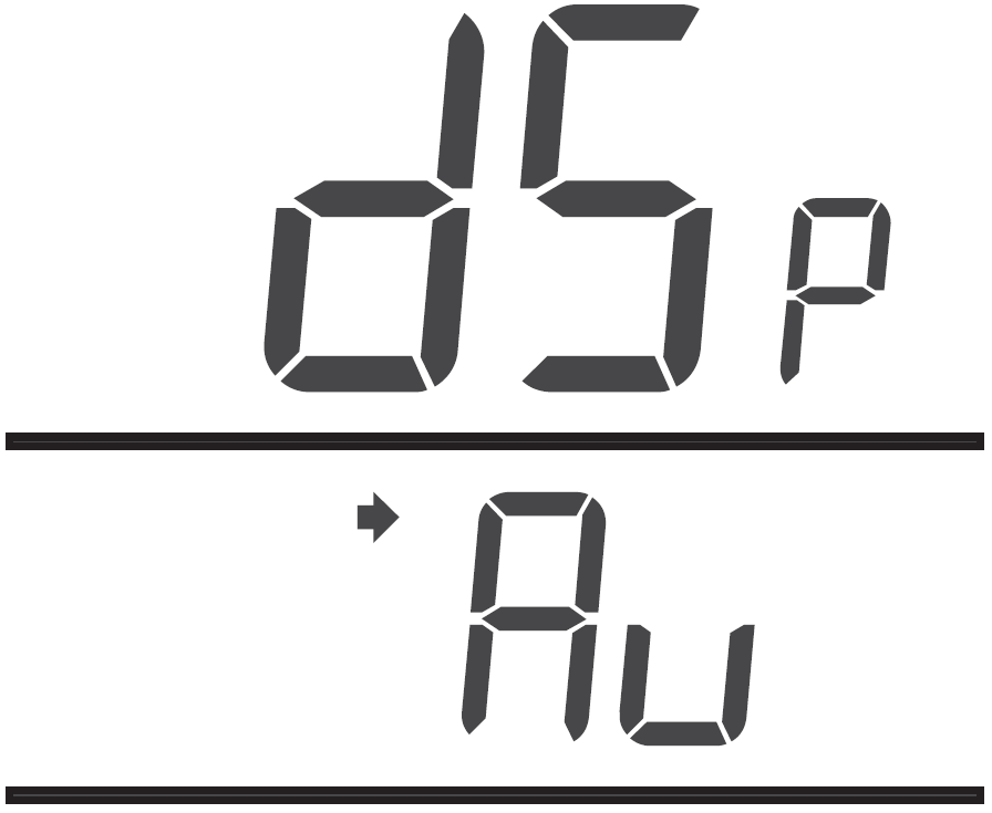
Display Format
Use this parameter to choose the temperature display mode. When the automatic mode is selected, the thermostat displays the temperature format set on the hydronic zoning controller. If °F or °C is selected, the thermostat displays the temperature in the selected format respectively.
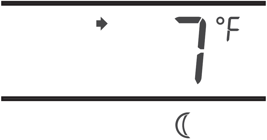
Temperature Setback
When the Unoccupied mode is activated by the hydronic zoning controller (certain controller models only), the temperature setpoint is lowered (set back). Use this parameter to specify the amount of temperature setback.
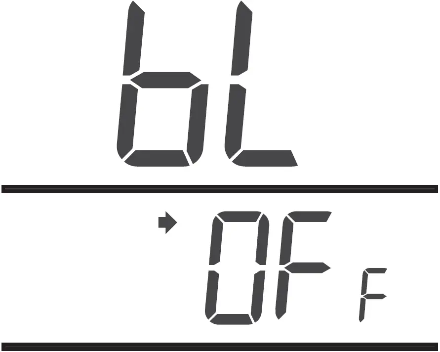
Backlight
Use this parameter to choose between temporary and permanent backlight. When temporary backlight is selected, the screen is lit for 12 seconds every time any button is pressed.
TEMPERATURE DISPLAY AND SETTING
The thermostat generally displays the actual (measured) temperature. To display the setpoint temperature, press one of the ▲▼ buttons once. The setpoint will be displayed for the next 5 seconds. An arrow appears at the left of the setpoint temperature display.To change the setpoint, press one of the ▲▼ buttons until the desired temperature is displayed. To scroll faster, press and hold the button.
Error Messages
- LO The measured temperature is below the thermostat’s display range.
- HI The measured temperature is above the thermostat’s display range.
- — Verify the thermostat and external (floor) sensor connections.
INSTALLATION
- Remove the faceplate from the base by unscrewing the screw underneath the thermostat and tilting the bottom of the faceplate up. Note that the screw remains captive on the base.
- Insert the wires through the center hole of the base and secure the base to the wall or onto an electrical box.
- Connect the wires to the terminals (no polarity to observe).
|
Terminal |
Description |
|
|
1 |
TH |
AQ2000 Series hydronic zoning controller connections |
|
2 |
TH |
|
|
3 |
SENSOR |
External sensor connections for floor temperature measurement (required only if the thermostat is set to F or AF mode) |
|
4 |
SENSOR |
- Set the configuration switches.
- Re-attach the faceplate to the base and secure with the captive screw.
NOTE: Keep the thermostat’s air vents clean and unobstructed at all times.
CONFIGURATION SWITCHES
The configuration (DIP) switches are located behind the thermostat faceplate.NOTE: DIP switch 1 is not used.
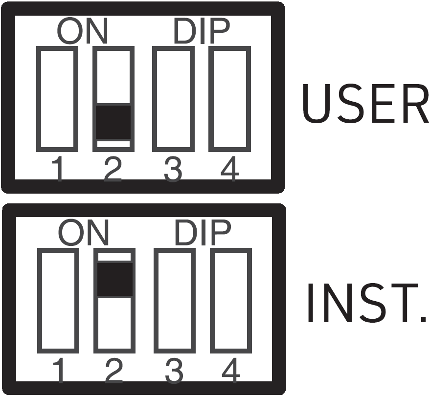
Use DIP switch 2 to set the thermostat in either Installer or User mode.
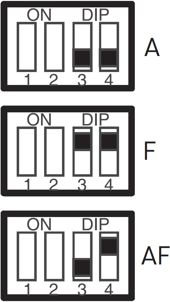
TEMPERATURE CONTROL MODE (SWITCHES 3 & 4)
Use DIP switches 3 and 4 to select the temperature control mode (A, F or AF).NOTE: F or AF mode should be used only when an external (floor) sensor is connected to the thermostat.
The parameters in the installer’s configuration menu must be modified by qualified personnel only. Incorrect settings can result in property damages.
- Remove the thermostat from its base.
- Place switch 2 on the back of the thermostat in the up position (Installer mode).
- Return the thermostat to its base. The first parameter is displayed.
- To modify a parameter, press either of the ▲▼ buttons.
- To view the next parameter, briefly press the backlight button.
- To exit the menu, place switch 2 back to its initial position.
The parameters appear in the order shown in the following table.
|
Parameter |
Default Setting |
Range |
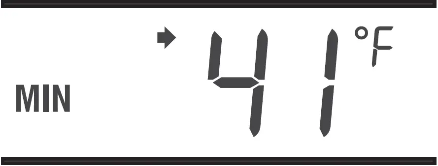
| Minimum setpoint temperature |
41°F (5°C) |
41°F (5°C) to 100°F (38°C) |
| Maximum setpoint temperature |
100°F (38°C) |
41°F (5°C) to 100°F (38°C) |
| Freeze Protection temperature |
41°F (5°C) |
41°F (5°C) to 100°F (38°C)* |
| Minimum floor limit |
41°F (5°C) |
41°F (5°C) to 100°F (38°C) |
| Maximum floor limit |
100°F (38°C) |
41°F (5°C) to 100°F (38°C) |
* The Freeze Protection temperature range is set by the minimum and maximum setpoint temperatures. For example, if you change the minimum setpoint temperature to 50°F (10°C), you cannot then set the Freeze Protection temperature lower than 50°F (10°C).
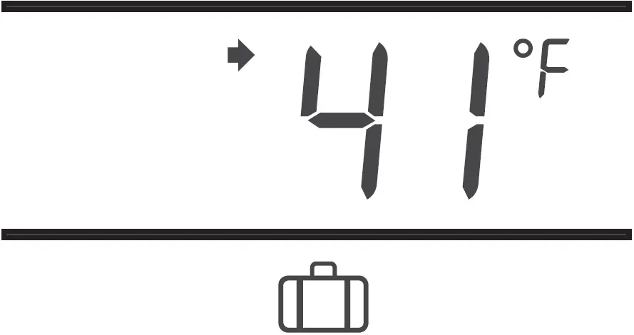
Minimum Setpoint Temperature
This parameter is the minimum temperature at which the thermostat can be set.
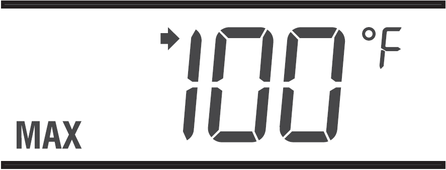
Maximum Setpoint Temperature
This parameter is the maximum temperature at which the thermostat can be set.
Freeze Protection Temperature
This parameter is used to prevent frozen pipes inside the room where the thermostat is located. When the Freeze Protection mode is activated by the hydronic zoning controller, the thermostat is placed at the Freeze Protection temperature.
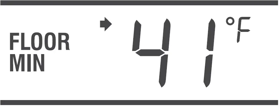
Minimum Floor Limit Temperature
This parameter is used only if the thermostat has been configured for AF temperature control. If the floor temperature is below that limit, the pump or valve will be activated regardless of the ambient temperature.
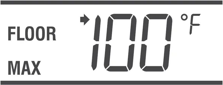
Maximum Floor Limit Temperature
This parameter is used only if the thermostat has been configured for AF temperature control. If the floor temperature is above that limit, the pump or valve will be deactivated regardless of the ambient temperature.
TECHNICAL SPECIFICATIONS
- Power Supply: powered by the boiler controller
- Default Setpoint Range: 40 °F to 100 °F (5 °C to 38 °C)
- Default Floor Limit (AF Model): 40 °F to 100 °F (5 °C to 38 °C)
- Setpoint Interval: ± 1.0 °F (0.5 °C)
- Indoor Temperature Display Range: 32 °F to 158 °F (0 °C to 70 °C)
- Outdoor Temperature Display Range: -58 °F to 212 °F (-50 °C to 100 °C) Display resolution: ± 1.0 °F (0.5 °C)
- Storage: -20 °F to 130 °F (-30 °C to 55 °C)
- Controller Type: Proportional Integral (PI)
- Memory Type: All settings are stored in non-volatile memory and are therefore safe during a power outage
2-YEAR LIMITED WARRANTY
Resideo warrants this product, excluding battery, to be free from defects in workmanship or materials, under normal use and service, for a period of two (2) years from the date of first purchase by the original purchaser. If at any time during the warranty period the product is determined to be defective due to workmanship or materials, Resideo shall repair or replace it (at Resideo’s option).If the product is defective,
- return it, with a bill of sale or other dated proof of purchase, to the place from which you purchased it; or
- call Resideo Customer Care at 1-800-468-1502. Customer Care will make the determination whether the product should be returned to the following address: Resideo Return Goods, 1985 Douglas Dr. N., Golden Valley, MN 55422, or whether a replacement product can be sent to you.
This warranty does not cover removal or reinstallation costs. This warranty shall not apply if it is shown by Resideo that the defect was caused by damage which occurred while the product was in the possession of a consumer.
Resideo’s sole responsibility shall be to repair or replace the product within the terms stated above. RESIDEO SHALL NOT BE LIABLE FOR ANY LOSS OR DAMAGE OF ANY KIND, INCLUDING ANY INCIDENTAL OR CONSEQUENTIAL DAMAGES RESULTING, DIRECTLY OR INDIRECTLY, FROM ANY BREACH OF ANY WARRANTY, EXPRESS OR IMPLIED, OR ANY OTHER FAILURE OF THIS PRODUCT.Some states do not allow the exclusion or limitation of incidental or consequential damages, so this limitation may not apply to you.THIS WARRANTY IS THE ONLY EXPRESS WARRANTY RESIDEO MAKES ON THIS PRODUCT. THE DURATION OF ANY IMPLIED WARRANTIES, INCLUDING THE WARRANTIES OF MERCHANTABILITY AND FITNESS FOR A PARTICULAR PURPOSE, IS HEREBY LIMITED TO THE TWO YEAR DURATION OF THIS WARRANTY. Some states do not allow limitations on how long an implied warranty lasts, so the above limitation may not apply to you.This warranty gives you specific legal rights, and you may have other rights which vary from state to state. If you have any questions concerning this warranty, please write Resideo Customer Care, 1985 Douglas Dr, Golden Valley, MN 55422 or call 1-800-468-1502.
Resideo Technologies, Inc.1985 Douglas Drive North, Golden Valley, MN 554221-800-468-1502
![]()
[xyz-ips snippet=”download-snippet”]