Honeywell Home HCW 82 Home Wireless Indoor Thermostat Devices
Overview
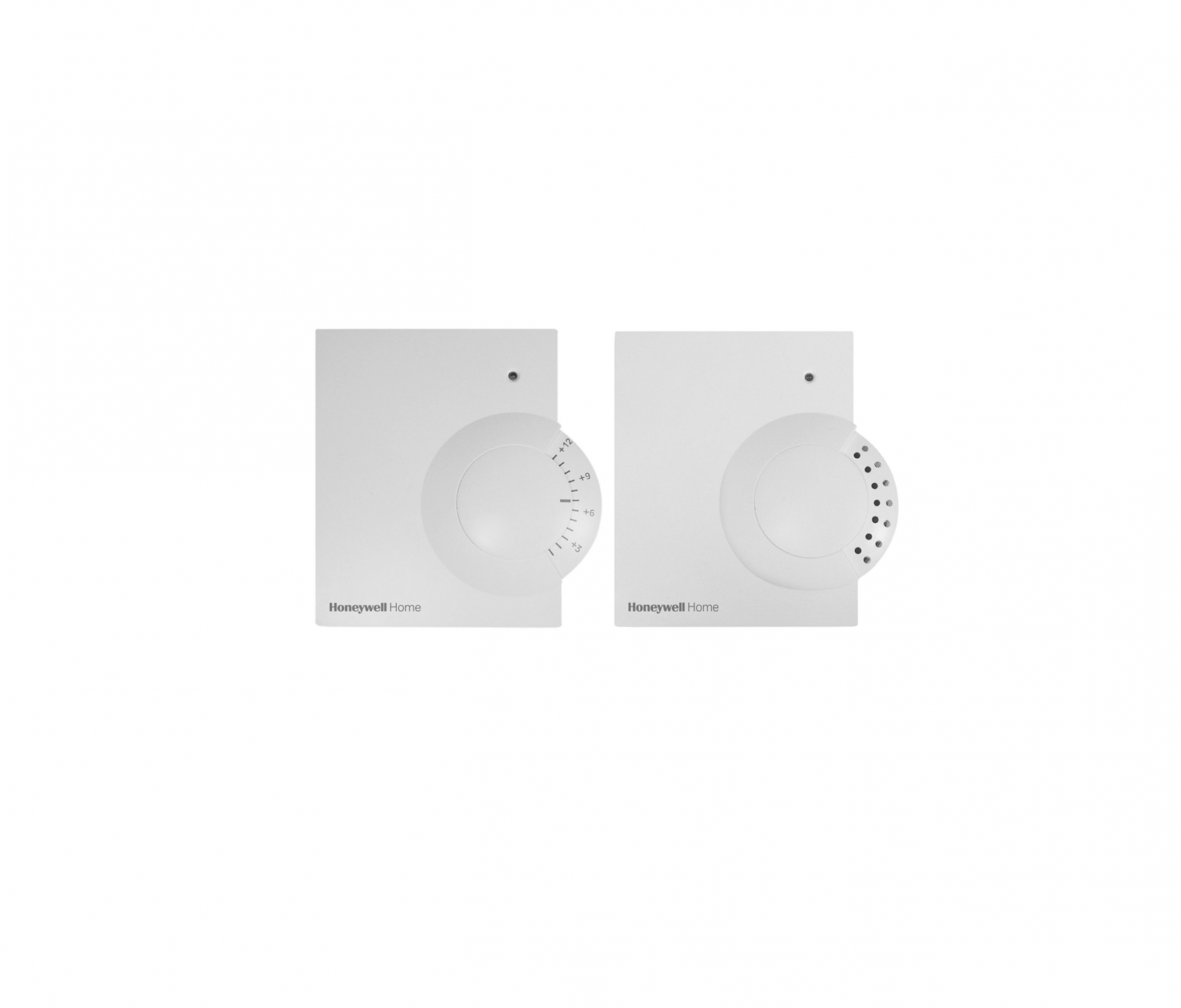
The HCW 82/HCF 82 room devices are used for intelligent room temperature control. The room temperature sensor HCF 82 measures the room temperature and sends the measured values to other devices.The HCW 82 measures the room temperature and additionally allows the room setpoint temperature to be adjusted.
Application
The room devices transfer the data with 868.3 MHz. The data can be received by other devices such as the underfloor heating controller HCE 80/HCC 80/HCE 80R/ HCC 80R or the evotouch.Thus a large spectrum of applications can be covered.
Differences HCW 82/HCF 82
The HCW 82 has the following functions in addition to those of the HCF 82:
- Connection possibility for an external power supply unit(see “Operation with an external power source”, down below).
- Connection possibility for a window contact(see “Installing the window contact”, down below).
- Adjustment dial at which you can change the room temperature setpoint directly.The adjustment range amounts to ± 12 °C, starting from the basic value of 20 °C (in position 0).
Scope of delivery
- 1 HCW 82/HCF 82
- 2 AA batteries
Commissioning
 Insufficient data transfer!Interference of the radio receiver in the device through metallic objects or further radio devices.
- Ensure there is sufficient distance to metallic objects.
- Mount the device with a distance of at least 1 m to radio devices such as radio headphones, cordless phones according to the DECT standard, etc.
- Select another installation site if the radio interference cannot be rectified.
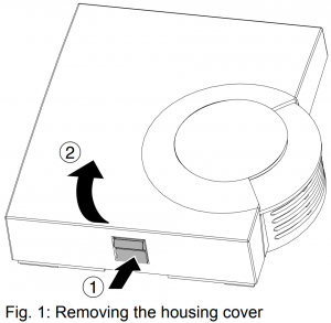
- Remove the housing cover of the room temperature sensor (see Fig. 1).

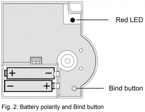
- Insert the supplied AA batteries with the correct battery polarity (see Fig. 2).The batteries have to be replaced when the red LED at the HCW 82/HCF 82 flashes (see “Changing batteries”, down below).
The setpoint adjuster HCW 82 can also be operated with an external power source instead of with batteries. Further information can be found in section “Operation with an external power source”, down below. - Place the room temperature sensor at the installation site, but do not install it yet.
- Allocate the corresponding temperature zone to the HCW 82/HCF 82 (see “Binding”, Page 8).
Binding
Assignment to underfloor heating controller
In order to assign a temperature zone to the HCW 82/ HCF 82, follow the instructions from the chapter entitled “Start-up” in the “Underfloor heating controller HCE 80/HCE 80R/ HCC 80/HCC 80R” installation instructions.
Assignment to evotouch
In order to assign a temperature zone to the HCW 82/ HCF 82, follow the instructions of the evotouch.
- Press the Bind button to carry out binding.
Failed binding
If the binding has failed:
- Improve the data transfer (see below).
- Repeat the binding procedure. Improving the data transfer
- When selecting the operating site of each device ensure that the distance to radio devices such as radio headphones, cordless phones, etc. according to the DECT standard amounts to at least 1 m.
- Do not install the devices over metallic wall connecting sockets and at least 30 cm away from the cover of the heat generator.
- Correct the installation site of the room temperature sensor if necessary.
Installation
- Remove the batteries.
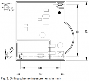
- Mark the drill holes according to the drilling template (see Fig. 3).
- Drill the holes.
- Screw on the room temperature sensor.
- Re-insert the batteries.
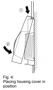
- Place the housing cover in position above and snap it down (see Fig. 4).
Particular features of HCW 82
Operation
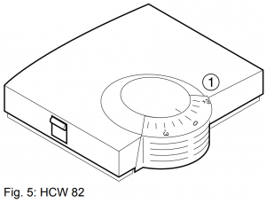
The room setpoint temperature can be set easily at the setpoint adjuster HCW 82 by means of an adjustment dial. The adjustment range amounts to ± 12 °C, starting from the basic value of 20 °C (in position 0)
- Select the desired change of the preset temperature at the adjustment dial (1) (see Fig. 5) (settings on the scale in °C).
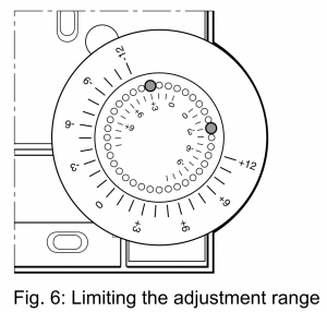
Limiting the adjustment range
You can limit the setting range that can be used at the adjustment dial.
- Remove the housing cover (see Fig. 1, above).
- Place the two small pins into the holes of the adjustment dials in order to limit the adjustment range (see Fig. 6).Orientate yourself on the basis of the inner scale:In Fig. 6, the pins are inserted so that the adjustment dial can only be adjusted by ±3 °C around the zero point.
- Turn the adjustment dial clockwise until it stops.
- Check whether the adjustment dial is in the position shown in Fig. 5.
- If appropriate, put the adjustment back in, rotated by 180° until it has the position shown.
- Turn the adjustment dial to Position 0.
- Place the housing cover in position above and snap it down (see Fig. 4)
 Orientate yourself on the basis of the inner scale:In Fig. 6, the pins are inserted so that the adjustment dial can only be adjusted by ±3 °C around the zero point.
Operation with an external power source
In addition to battery operation, the setpoint adjuster HCW 82 is also prepared for operation with an external power source.
|
Damage to the device!Use of an unsuitable power supply unit.
|
- Have a power supply unit with 3 V DC ± 10 %, min. 25 mA at hand.
- De-energize the power supply unit.
- Remove the housing cover of the HCW 82 (see Fig. 1, above).
- Remove the batteries.
Dispose of the batteries according to the local statutory requirements and not with the used domestic refuse - Unscrew the setpoint adjuster HCW 82.
The maximum permissible cable length from the power supply unit to the device amounts to 100 m. If possible, use a cable of the type JE-Y (ST)Y 2x2x0.8 mm or JE-LIYCY 2x2x0.5 mm2 . - Lead the outlet cable of the power supply unit through the housing opening (1) (see Fig. 7) to the inside.
- Connect the outlet cable to the terminal (2) (see Fig. 7).– Connection 2: Earth– Connection 3: Voltage
- Screw the setpoint adjuster HCW 82 back on.
- Place the housing cover in position above and snap it down (see Fig. 4).
 Dispose of the batteries according to the local statutory requirements and not with the used domestic refuse
Installing the window contact
- Connect any sensor with floating contact to the HCW 82 (installation to connection 1 and connection 2, see Fig. 7(2), Page 9).
- For commissioning follow the instructions of the device to which the window contact is assigned.
If several floating contacts are used, these have to be connected in series.
Changing batteries
Change the batteries if the red LED of the room temperature sensor flashes and the device is not in test mode.
- Remove the housing cover of the HCW 82/HCF 82 (see Fig. 1).
- Remove the batteries.
Dispose of the batteries according to the local statutory requirements and not with the used domestic refuse.Always replace both batteries together. Only use 1.5 V batteries of the type LR06, AA. - Insert the batteries with the right polarity into the battery compartment (see Fig. 2).
- Place the housing cover on at the top and latch it in downwards (see Fig. 4).
Checking radio transmission
The HCW 82/HCF 82 can send a test signal to the allocated receiver (for example an underfloor heating controller) in order to test the signal strength.
- Keep the Bind button pressed for at least 30 s until the red LED extinguishes.The device is now in test mode and sends a test signal every 5 seconds.The LED flashes briefly at every test signal.
- Check the radio transmission at the receiver. Refer to the respective instructions for information about receiving and evaluating the test signals.
The test mode is terminated automatically after 5 minutes. The test mode can also be terminated by removing the batteries, manual disconnection of the power supply or by pressing the Bind button.
Help with problems
| Problem | Cause | Remedy |
| Binding failed | Batteries inserted incorrectly |
|
| Radio connection failure |
|
Technical data
| Batteries | 1.5 V, type LR06, AA |
| Power supply unit | 3 V DC ± 10 %, min. 25 mA |
| Cable for power supply unit/window contact | Ø 2×0.8 mm; 2×0.5 mm² max. length 100 m |
| Frequency | 868.3 MHz (transmitter) |
WEEE directive 2002/96/ EC – Waste Electrical and Electronic Equipment directive
- At the end of the product life dispose of the packaging and product in a corresponding recycling center.
- Do not dispose of the unit with the usual domestic refuse.
- Do not burn the product.

[xyz-ips snippet=”download-snippet”]