Honeywell Home RLV3150 Electronic Thermostat Installation Guide
APPLICATION
This thermostat is designed to control an electric heating system such as a baseboard heater, a convector or a fanforced heater.
The thermostat cannot be used with the following:
- a resistive load under 2 A
- a resistive load over 12.5 A
- systems driven by a contactor or a relay (inductive load)
- central heating systems
Supplied Parts
- One (1) thermostat
- Two (2) 6-32 mounting screws
- Two (2) solderless connectors
CONTROLS AND DISPLAY
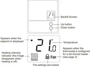 Figure: 1
INSTALLATION GUIDELINES
![]() WARNINGTURN OFF POWER TO THE HEATING SYSTEM AT THE MAIN POWER PANEL TO AVOID ELECTRICAL SHOCK.
WARNINGTURN OFF POWER TO THE HEATING SYSTEM AT THE MAIN POWER PANEL TO AVOID ELECTRICAL SHOCK.
- The installation must comply with local electrical codes.
- Do NOT install the thermostat in an area where it can be exposed to water or rain.
- Avoid locations where there are air drafts (such as the top of a staircase or an air outlet), dead air spots (such as behind a door), or direct sunlight.
- Do not install the thermostat on a wall section that conceals air ducts, chimney pipes or stove pipes.
- Install the thermostat about 1.5 m (5 feet) high, on an inside wall facing the heater.
- Install the thermostat onto an electrical box.
- This thermostat has tinned copper wires for line and load connections. Special CO/ALR solderless connectors must be used if the thermostat will be connected to aluminum wires.
- The thermostat wires are not polarized; either wire can be connected to the load or to the power supply.
- Keep the air vents at the top and bottom of the thermostat clean and free from obstructions.
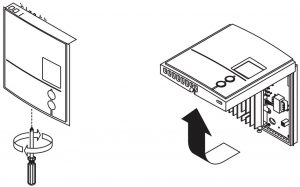
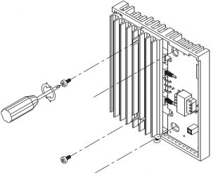
MOUNT THE THERMOSTAT
- Loosen the screw underneath the thermostat and separate the faceplate from the wallplate.NOTE: The screw remains captive and cannot be completely removed.

- Wire the thermostat (see “Wiring” on page 3).
- Mount the wallplate to the electrical box using the provided screws. Insert the screws through the two left or right mounting holes of the wallplate.
- Set the configuration switches (see “Configuration Settings” on page 4).
- Reinstall the faceplate onto the wallplate and tighten the screw.NOTE: If there is a protective film or sticker on the thermostat’s screen, peel it off.
- Apply power to the heating system. Verify the installation by checking that the heating system can be turned On by raising the setpoint using the Up button or turned Off by lowering the setpoint using the Down button.
WIRING
Connect the thermostat wires to the heating system (load) and to the power supply.
- 2-wire Installation
- 4-wire InstallationFig. 4. 2-wire and 4-wire installation.
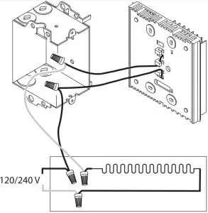
 Fig. 4. 2-wire and 4-wire installation.
CONFIGURATION SETTINGS
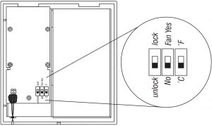
Configuration switches are on the back of the faceplate. Factory settings are inside gray cells.
| # | Parameter | Up | Down |
| 1 | Settings lock¹ | Lock | Unlock |
| 2 | Fan-forced heater² | Fan Yes | No |
| 3 | Unit | °F | °C |
- The thermostat buttons are disabled and appears on the screen (see page 1) when the settings are locked.
- Place at Fan Yes if you have a fanforced heater (to prevent premature burnout of the motor). Leave at No for better temperature regulation if you do not have a fanforced heater.
TEMPERATURE DISPLAY AND SETTING
The thermostat generally displays the room temperature.
- To display the set temperature(setpoint), press the Up or Down button once. The setpoint temperature will remain on the screen for 5 seconds.
- To change the setpoint temperature, press the Up or Down button repeatedly until the desired temperature is displayed.
- The screen is backlit for 10 seconds when any button is pressed.
- Press the Up and Down buttons simultaneously for three seconds to enter the setup menu.
- Press the Up or Down button to change the option.
- Press the Up and Down buttons simultaneously and briefly to advance to the next parameter.
- When the last parameter is displayed, press the Up and Down buttons for three seconds to save any changes and exit the menu.NOTE: If you do not press any button for 15 seconds, the thermostat will automatically save any changes you have made and will then return to its normal display.
| Parameter | Options | Display and default setting |
| Minimum setpoint | 5°C – 30°C (41°F – 86°F)NOTE: The minimum setpoint cannot be set higher than the value set for the maximum setpoint. |  |
| Maximum setpoint | 5°C – 30°C (41°F – 86°F)NOTE: The maximum setpoint cannot be set lower than the value set for the minimum setpoint. | 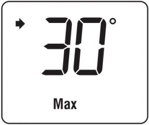 |
IN CASE OF DIFFICULTY
| PROBLEM | SOLUTIONS |
| Thermostat is hot | This is normal unless the thermostat is too hot to touch. Ensure that the heater capacity does not exceed the thermostat’s maximum load. |
| Wrong temperature is displayed. | Avoid any of the following conditions: The thermostat is exposed to an air draft. The thermostat is located near or above a heat source such as a light dimmer. |
| Display disappears and reappears after a few minutes. | The thermal circuit breaker on the heater has temporarily opened. This can happen if the heater is obstructed by furniture or curtain and has overheated, or if the thermal circuit breaker is defective or too sensitive. |
| Display looks faded when heating is activated. | The heater capacity is probably less than the thermostat minimum load requirement. The thermostat cannot be used below that rating. |
SPECIFICATIONS
- Supply: 240 VAC, 60 Hz
- Minimum load: 2 A (resistive only) 500 W @ 240 VAC
- Maximum load: 12.5 A (resistive only) 3000 W @ 240 VAC
- Display range: 0°C to 50.0°C (32°F to 122°F)
- Setpoint range: 5.0°C to 30.0°C (41°F to 86°F)
- Resolution: 0.5°C (1°F)
- Operating temperature: 0°C to 50.0°C (32°F to 122°F)
- Storage: -20.0°C to 50.0°C (-4°F to 122°F)
- Permanent Memory: You do not need to adjust the temperature or thermostat configurations following a power outage.
1-YEAR LIMITED WARRANTY
Resideo warrants this product, excluding battery, to be free from defects in workmanship or materials, under normal use and service, for a period of one (1) year from the date of first purchase by the original purchaser. If at any time during the warranty period the product is determined to be defective due to workmanship or materials, Resideo shall repair or replace it (at Resideo’s option).
If the product is defective,
- return it, with a bill of sale or other dated proof of purchase, to the place from which you purchased it; or
- call Resideo Customer Care at 1-800-468-1502. Customer Care will make the determination whether the product should be returned to the following address: Resideo Return Goods, 1985 Douglas Dr. N., Golden Valley, MN 55422, or whether a replacement product can be sent to you.
This warranty does not cover removal or reinstallation costs. This warranty shall not apply if it is shown by Resideo that the defect was caused by damage which occurred while the product was in the possession of a consumer
Resideo’s sole responsibility shall be to repair or replace the product within the terms stated above. RESIDEO SHALL NOT BE LIABLE FOR ANY LOSS OR DAMAGE OF ANY KIND, INCLUDING ANY INCIDENTAL OR CONSEQUENTIAL DAMAGES RESULTING, DIRECTLY OR INDIRECTLY, FROM ANY BREACH OF ANY WARRANTY, EXPRESS OR IMPLIED, OR ANY OTHER FAILURE OF THIS PRODUCT.
Some states do not allow the exclusion or limitation of incidental or consequential damages, so this limitation may not apply to you.
THIS WARRANTY IS THE ONLY EXPRESS WARRANTY RESIDEO MAKES ON THIS PRODUCT. THE DURATION OF ANY IMPLIED WARRANTIES, INCLUDING THE WARRANTIES OFMERCHANTABILITY AND FITNESS FOR A PARTICULAR PURPOSE, IS HEREBY LIMITED TO THE ONE YEAR DURATION OF THIS WARRANTY. Some states do not allow limitations on how long an implied warranty lasts, so the above limitation may not apply to you.
This warranty gives you specific legal rights, and you may have other rights which vary from state to state. If you have any questions concerning this warranty, please write Resideo Customer Care, 1985 Douglas Dr, Golden Valley, MN 55422 or call 1-800-468-1502.
CUSTOMER ASSISTANCE
If you have any questions about the product installation or operation, or concerning the warranty, contact us at:
Resideo1985 Douglas Drive NorthGolden Valley, MN 55422USA
1-800-468-1502
For more information on our products, go to: honeywellhome.com
CAUTION: ELECTRONIC WASTE NOTICEThe product should not be disposed of with other household waste. Check for the nearest authorized collection centers or authorized recyclers. The correct disposal of end-of-life equipment will help prevent negative consequences for the environment and human health.
Customer Support
Resideo Technologies, Inc.1985 Douglas Drive North, Golden Valley, MN 554221-800-468-150233-00209ES—05 M.S. Rev. 01-21 | Printed in United States
© 2021 Resideo Technologies, Inc. All rights reserved.The Honeywell Home trademark is used under license from Honeywell International, Inc. This product is manufactured by Resideo Technologies, Inc. and its affiliates.
References
[xyz-ips snippet=”download-snippet”]