
Honeywell Home T8775C The Digital Round Non-Programmable Thermostat
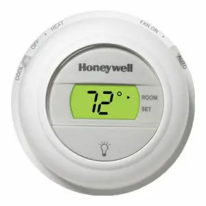
The T8775A,C Thermostats provide single-stage temperature control for 24V systems. The T8775A,C models include a thermostat, wallplate (for wiring and mounting thermostat), mounting screws, wall anchors, and a 4074 FAB resistor.
MERCURY NOTICEIf this control is replacing a control that contains mercury in a sealed tube, do not place your old control in the trash. Contact your local waste management authority for instructions regarding recycling and the proper disposal of an old control containing mercury in a sealed tube.
INSTALLATION
When Installing this Product...
- Read these instructions carefully. Failure to follow them could damage the product or cause a hazardous condition.
- Check the ratings given in the instructions and on the product to make sure the product is suitable for your application.
- Installer must be a trained, experienced service technician.
- After installation is complete, check out product operation as provided in these instructions.
![]() CAUTIONElectrical Shock or Equipment Damage Hazard.Can shock individuals or short equipment circuitry.Disconnect power supply before installation.
CAUTIONElectrical Shock or Equipment Damage Hazard.Can shock individuals or short equipment circuitry.Disconnect power supply before installation.
LocationInstall the thermostat about 5 ft (1.5m) above the floor in an area with good air circulation at average temperature. Do not install the thermostat where it can be affected by:— drafts or dead spots behind doors and in corners.— hot or cold air from ducts.— radiant heat from the sun or appliances.— concealed pipes and chimneys.— unheated (uncooled) areas such as an outside wall behind the thermostat.
Mounting Wall plate to WallMount the T8775A,C wall plate, with the screws provided. See Fig. 1.
Wiring
IMPORTANTUse 18-gauge wire to wire the T8775A,CThermostats.
All wiring must comply with local electrical codes and ordinances. Disconnect the power supply to prevent electrical shock or equipment damage.
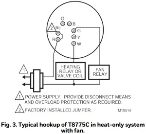
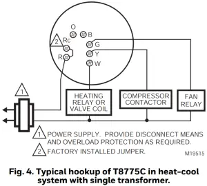
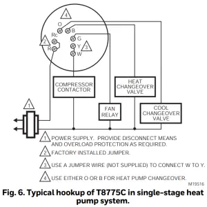
Refer to Fig. 2 through 6 for typical wiring hookups.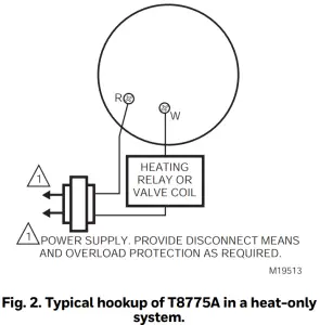

CUSTOMIZE THERMOSTAT
Setting Fuel Switch (T8775C only)The fuel switch is preset at the factory in the F position. See Fig. 7. This is the correct setting for gas or oil systems. If the T8775C is being installed on an electric heat system, or a heat pump, set the switch to the E position. The E setting allows the fan to turn on immediately with the heating equipment in a system where the G terminal is connected.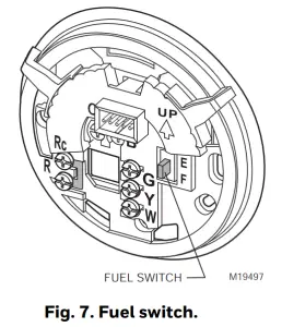
DIP SwitchTo adjust the heat cycle rate or theFahrenheit/Celsius indication, locate DIP switch 1, 2 and 3 on the back of the thermostat. See Fig. 8.
Set Heat Cycle RateUse DIP switches 1 and 2 to set the heat cycle rate. See Table 1.
Table 1. Heat Cycle Rate
| Heating System | Cycles Per Hour | DIP Switch 1 | DIP Switch 2 |
| Steam, Gravity | 1 | On | On |
| High Efficiency Warm Air (90%+ efficiency), Hot Water, Heat Pump | 3 | Off | On |
| Gas or Oil Warm Air (factory setting) | 6 | Off | Off |
| Electric Warm Air | 9 | On | Off |
| In Floor Radiant Heat | Check with manufacturer for recommended cycle rate. |
Fahrenheit/Celsius IndicationUse DIP switch 3 to set the desired temperature indication. See Table 2
Table 2. Temperature Indication
| Fahrenheit/Celsius Display | DIP Switch 3 |
| Fahrenheit (factory setting) | Off |
| Celsius | On |
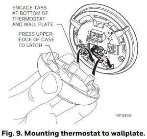
Mounting Thermostat to Wall plate
OPERATION
Setting SYSTEM and FAN Switches (T8775C only)System and fan settings are controlled manually by using the switches located at the top of the thermostat. See Fig. 10.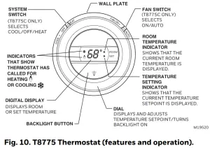
SYSTEM SwitchHeat: The thermostat controls the heating system.Off: Both heating and cooling systems are off.Cool: The thermostat controls the cooling system.
FAN SwitchAuto: The fan only runs with the heating and cooling system.On: The fan runs continuously. Use for improved air circulation.
CHECKOUT
NOTE: Temperature setpoint range is 40°F to 90°F (4°C to 32°C) in heating and 45°F to99°F (7°C to 37°C) in cooling.
Heating
- Slide the SYSTEM switch to Heat and the FAN switch to Auto (T8775C only).
- Raise the temperature setpoint several degrees above the room temperature.
- A flame
 will appear in the display and the heat should turn on.
 - Lower the temperature setpoint below the room temperature.
- The flame will disappear from the display and the heat should turn off.
Cooling (T8775C only)
![]() CAUTIONLow Temperature Hazard. Operating at too low of an outdoor temperature may cause compressor damage.Do not operate cooling if outdoor temperature is below 50°F (10°C). Refer to manufacturer’s recommendations.
CAUTIONLow Temperature Hazard. Operating at too low of an outdoor temperature may cause compressor damage.Do not operate cooling if outdoor temperature is below 50°F (10°C). Refer to manufacturer’s recommendations.
NOTE: If a call for cooling is made before the compressor has been off for five minutes, or if a power interruption occurs while the compressor is running, the thermostat will go into a five-minute delay to protect the compressor. The snowflake ![]() will flash during this delay
will flash during this delay
- Slide the SYSTEM switch to Cool and the FAN switch to Auto.
- Lower the temperature setpoint several degrees below the room temperature.
- After approximately five minutes, the thermostat will display a solid snowflake and the cooling should turn on.
- Raise the temperature setpoint above the room temperature.
- The snowflake will disappear from the display and the cooling should turn off.
Fan
- Slide the SYSTEM switch to Off and the FAN switch to On. The fan should run continuously.
- Slide the FAN switch to Auto. The fan should turn off.
Resideo Technologies, Inc.1985 Douglas Drive North, Golden Valley, MN 55422 1-800-468-1502

© 2020 Resideo Technologies, Inc. All rights reserved.The Honeywell Home trademark is used under license from Honeywell International, Inc.This product is manufactured by Resideo Technologies, Inc. and its affiliates.
report this ad![]()
[xyz-ips snippet=”download-snippet”]