Honeywell Home TH6100AF2004 T6 Pro Hydronic
Programmable Thermostat Installation Guide
 Installation Instructions
 Installation Instructions
Package Includes:
- T6 Pro Hydronic Programmable Thermostat
- Floor sensor (model AC112-01)
- UWPTM Mounting System
- Decorative Cover Plate
- Screws and anchors
- 2 AA Batteries
- Thermostat Literature
Welcome!
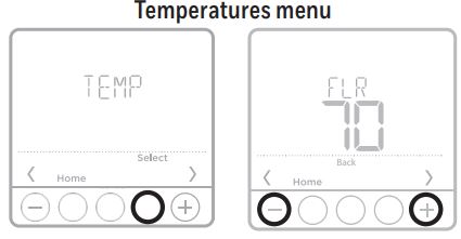
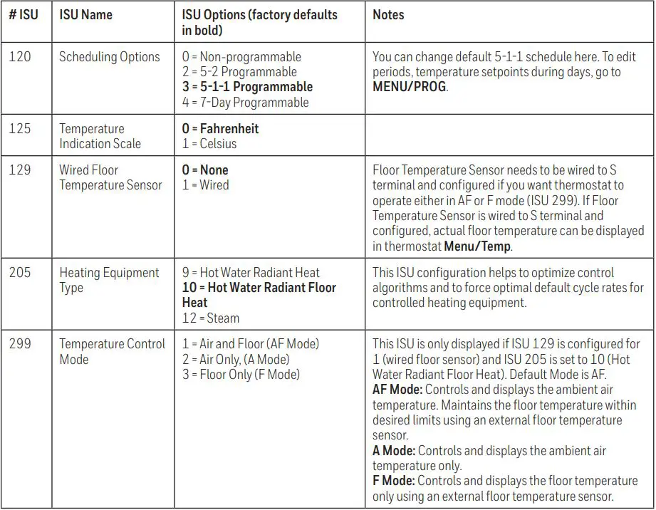
T6 Pro Hydronic Programmable Thermostat can be used to control the ambient air temperature or floor temperature or both. You can choose among the following temperature control modes.
A mode: Controls and displays the ambient air temperature only.
F mode: Controls and displays the floor temperature only using an external floor temperature sensor. This control mode is suitable for areas such as bathrooms where floor temperature could be scheduled to be warm only during occupied, morning and evening periods.
- Floor temperature is indicated by “FLR” above the actual floor temperature.
- Actual ambient air temperature could also be displayed in the Thermostat MENU/TEMP.
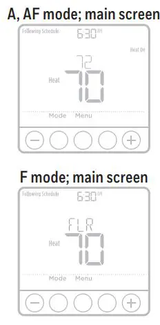 AF mode: Controls and displays the ambient air temperature as well as maintains the floor temperature within desired floor temperature limits using an external floor temperature sensor. Setting the minimum and maximum floor temperature limits is a way to enhance comfort and to protect the floor covering at the same time.
- Actual floor temperature could also be displayed in the Thermostat MENU/ TEMP.
NOTE: To set the thermostat temperature control mode, go to “Installer setup (ISU)” on page 7.
Read before installing
Optional Cover Plate installation
NOTE: If Optional Cover Plate is not required, see “UWP Mounting System installation” below.Use the Optional Cover Plate when you need to cover paint gap from the old thermostat.There are different cover plates depending on when the thermostat was manufactured. One plate is square, the other is rectangular.
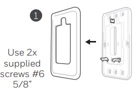
- If the square mounting plate is used, separate the cover plate from the mounting plate. See Figure 1.
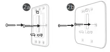
- Mount the mounting plate to the wall using any of the screw holes. Insert and tighten mounting screws supplied with the cover plate. Do not overtighten. Make sure the mounting plate is level. See Figure 2a (square) or 2b (rectangle).
- Attach the UWP by hanging it on the top hook of the mounting plate and then snapping the bottom of the UWP in place. See Figure 3.
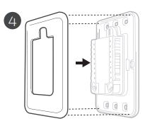
- For square cover plate, snap the Cover Plate onto the mounting plate. See Figure 4.UWP Mounting System installation
- Before starting, turn the power off at the breaker box or switch. Open package to find the UWP. See Figure 5.
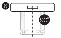
- Position the UWP on wall. Level and mark hole positions. See Figure 6.Drill holes at marked positions, and then lightly tap supplied wall anchors 7 into the wall using a hammer.If your box contains red anchors, use a 7/32″ (5.6 mm) drill bit. If your box contains yellow anchors, use a 3/16″ (4.8 mm) drill bit.
- Pull the door open and insert the wires through wiring hole of the UWP. See Figure 7.
- Place the UWP over the wall anchors. Insert and tighten mounting screws supplied with the UWP. Do not overtighten. Tighten until the UWP no longer moves. Close the door. See Figure 8.
 UWP Mounting System installation

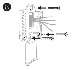
Use 3x supplied screws (#8 1-1/2 for red anchors and #6 1-1/2 for yellow anchors)
Power options

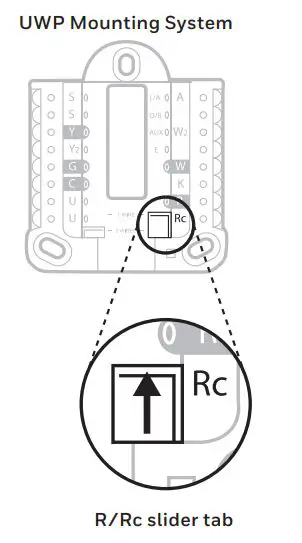
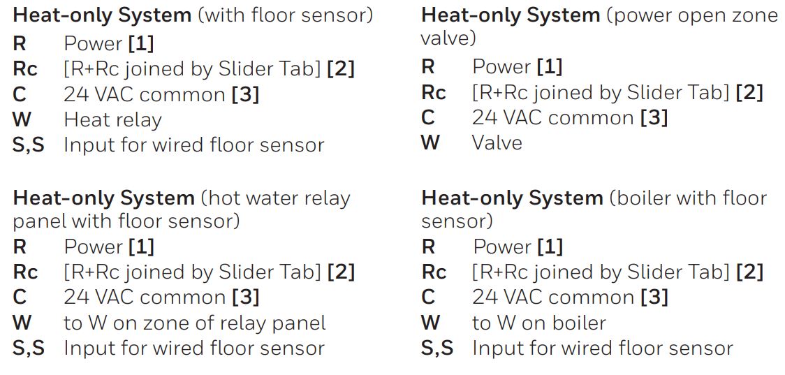
Setting Slider Tabs
Set R Slider Tab.
- Boiler, hot water valve circuit, or hot water relay panel wires to R and W. If the same transformer is providing common to power the thermostat, wire the transformer common to C and leave the R slider tab in the up position (1 wire). If a transformer that is not powering the heating equipment is used to power the thermostat display, set the R slider tab to the down position (2 wires). Wire the heat circuit to R and W, then wire the separate transformer to Rc and C.
NOTE: Slider Tabs for U terminals should be left in place for this thermostat model.
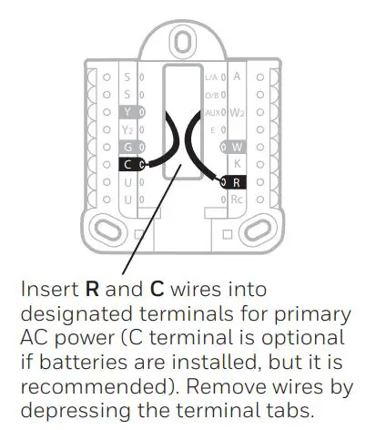
Wiring terminal designations
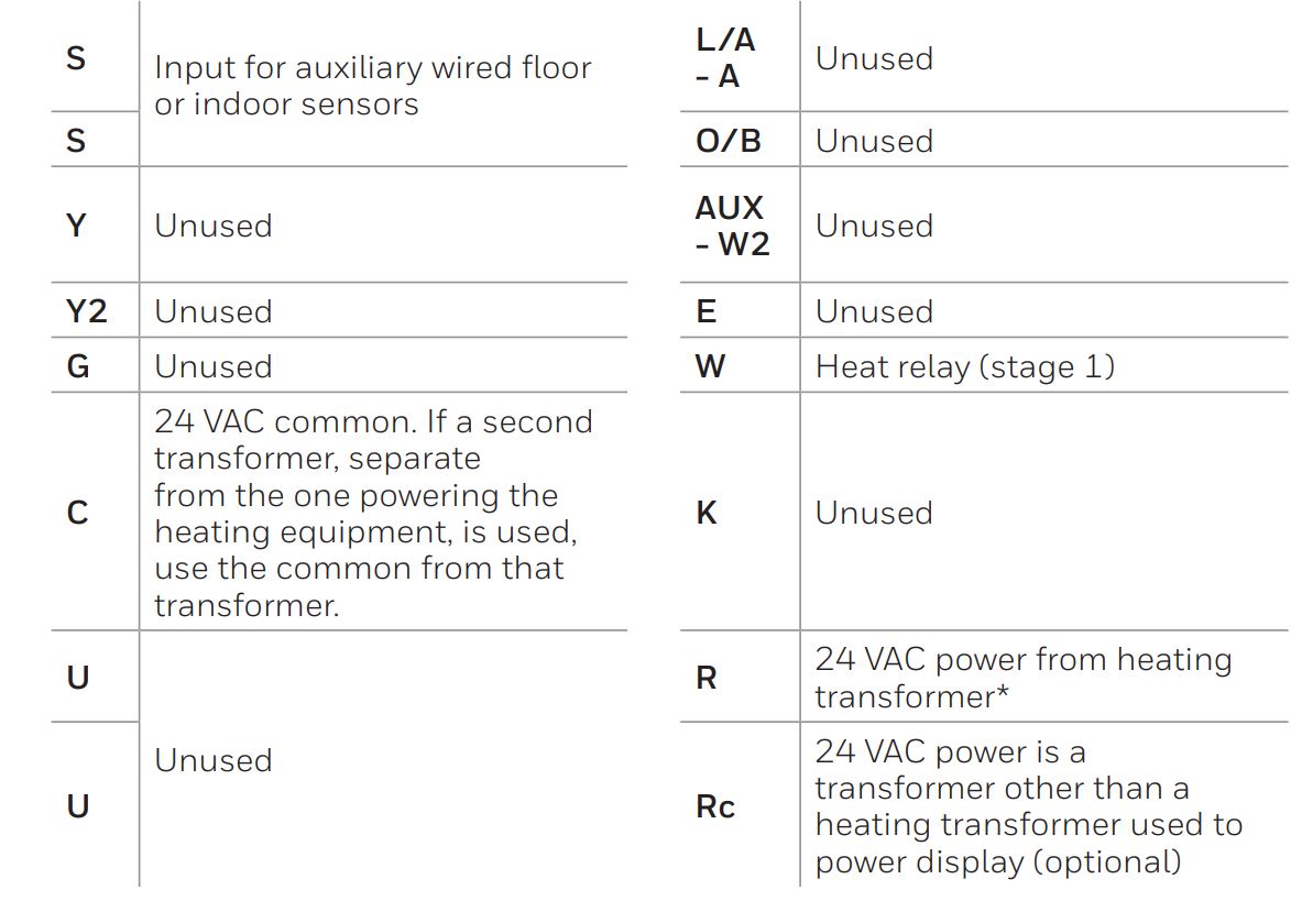
* Terminal can be jumped using Slider Tab. See “Setting Slider Tabs” on page 3.
Wiring conventional systems
NOTES Wire specifications: Use 18- to 22-gauge thermostat wire. Shielded cable is not required.[1] Power supply. Provide disconnect means and overload protection as required.[2] Move R-Slider Tab on UWP to the R (1 wire) setting. For more information, see “Setting Slider Tabs” on page 3.[3] Optional 24 VAC common connection.
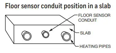
Floor temperature sensor installation
T6 Pro Hydronic thermostat is compatible with the following 10K ohm floor temperature sensors: AQ12C20 and AC112-01.
The floor temperature sensor needs to be installed mid way between the piping to ensure proper temperature reading (not over or right next to piping). Example: For a 12″ pipe spacing install the sensor 6″ away from the piping and ensure the sensor is vertically centered.
We recommend installing the floor temperature sensor inside of min. 0.5” PEX pipe. This simplifies future sensor replacement, if required.
In a small room, position the sensor in the center of the floor. In larger rooms, ensure the sensor is at least 7 feet from the wall.
Recommended floor temperatures settingsRecommended maximum floor temperature is 90 °F (32 °C) for most floor covering types except wood. Suggested maximum floor temperature for wood floor is 85 °F (29.5 °C). Freeze protection temperature for garages and basements is suggested to be set between 41 °F – 45 °F (5 °C – 7.2 °C).
Thermostat mounting
- Push excess wire back into the wall opening.
- Close the UWP door. It should remain closed without bulging.
- Align the UWP with the thermostat, and push gently until the thermostat snaps in place.
- Turn the power on at the breaker box or switch.

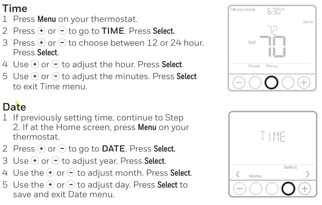
Set the time and date
System operation settings
 System operation settings
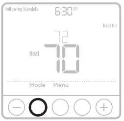
- Press the Mode button to cycle to the next available System mode.
- Cycle through the modes until the required System mode is displayed and leave it to activate.
Available System modes:– Heat– Off
Installer setup (ISU)
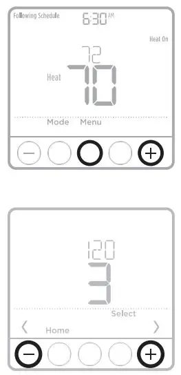
- Press and hold CENTER and buttons for approximately 3 seconds to enter advanced menu.
- Press Select to enter ISU.
- Press Select to cycle through menu setup options.
- Press or to change values or select from available options.
- Press Select and confirm your settings or press Back to ignore changes and return to ISU menu screen to continue editing another setup option.
- To finish setup process and save your setting, press Home and return to Home screen.
NOTE: A complete list of all setup (ISU) parameters and options starts below and continues through page 9.
Advanced setup options (ISU)
NOTE: Depending on system settings, not all options may be available.

Installer system test
To perform a System Test:
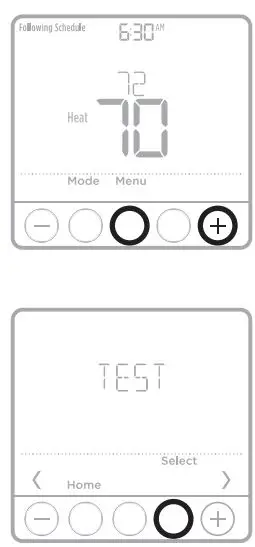
- Press and hold CENTER and (+) buttons for approximately 3 seconds to enter advanced menu.
- Use(+) to go to TEST. Press Select to enter System Test.
- Use (+)to change between Heat or Ver (thermostat version information). Press Select.
- Press(+) to turn heat on. Press(–) to turn heat off.
- Use the Home button to exit the System Test.
Alerts
Active alerts are displayed via the alert![]() symbol and alert number in the clock area on the home screen. You can read more information about active alerts, snooze or dismiss non-critical alerts in MENU/ALRT.
symbol and alert number in the clock area on the home screen. You can read more information about active alerts, snooze or dismiss non-critical alerts in MENU/ALRT.
![]()
Specifications
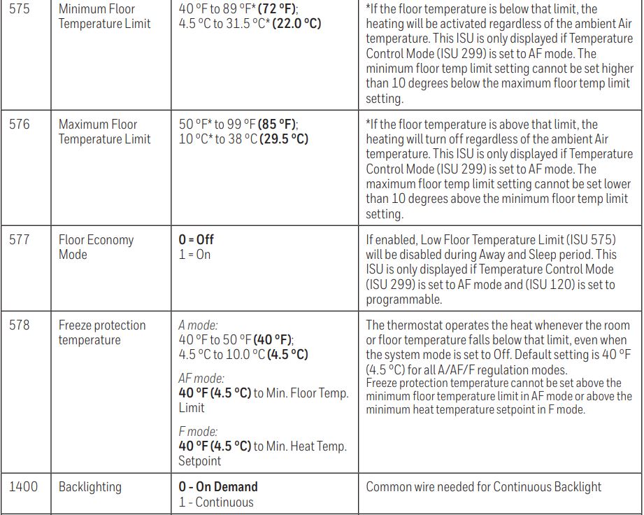
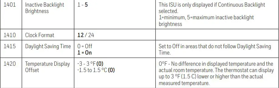
Temperature Setpoint and Limit RangesSee ISU settings 431, 432, 575, 576, and 578 starting on page 8.
Working Ambient Temperature32 °F to 120 °F (0 C° to 48.9 °C)
Operating Ambient Temperature37 °F to 102 °F (2.8 °C to 38.9 °C)
Shipping Temperature-20 °F to 120 °F (-28.9 °C to 48.9 °C)
Operating Relative Humidity5% to 90% (non-condensing)
Physical Dimensions in inches (mm) (H x W x D)4-1/16″ H x 4-1/16″ W x 1-5/32″ D103.5 mm H x 103.5 mm W x 29 mm D
Electrical Ratings 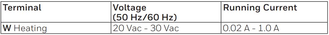
![]() CAUTION: ELECTRICAL HAZARDCan cause electrical shock or equipment damage. Disconnect power before beginning installation.
CAUTION: ELECTRICAL HAZARDCan cause electrical shock or equipment damage. Disconnect power before beginning installation.
![]() CAUTION: MERCURY NOTICEIf this product is replacing a control that contains mercury in a sealed tube, do not place the old control in the trash. Contact your local waste management authority for instructions regarding recycling and proper disposal.
CAUTION: MERCURY NOTICEIf this product is replacing a control that contains mercury in a sealed tube, do not place the old control in the trash. Contact your local waste management authority for instructions regarding recycling and proper disposal.
Customer assistance
For assistance with this product, please visit customer.resideo.comOr call Resideo Customer Care toll-free at1-800-468-1502
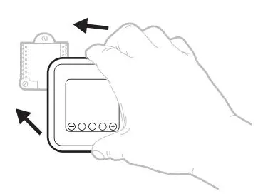
Pull to remove the thermostat from the UWP.

Resideo Technologies, Inc. 1985 Douglas Drive North, Golden Valley, MN 55422 1-800-633-3991 33-00340EFS–07 M.S. Rev. 05-20 | Printed in United States
 report this ad
©2020 Resideo Technologies, Inc. All rights reserved. The Honeywell Home trademark is used under license from Honeywell International, Inc. This product is manufactured by Resideo Technologies, Inc. and its affiliates. 
[xyz-ips snippet=”download-snippet”]