Honeywell Home THP2400A1019 Cover Plate Assembly
INSTALLATION GUIDE
APPLICATION
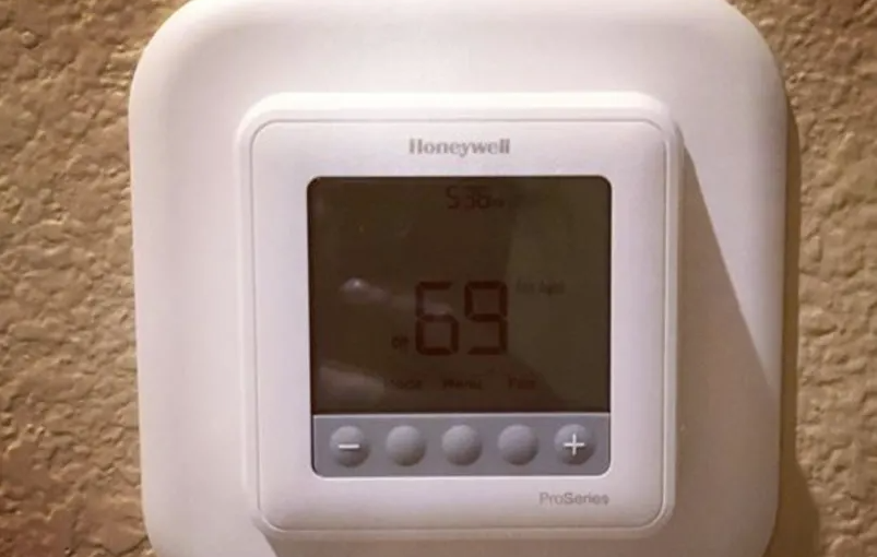
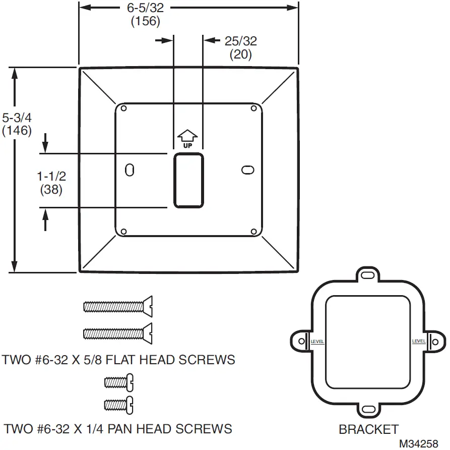
Use the THP2400A1019 cover plate assembly with the RedLINK™ VisionPRO® or Wi-Fi VisionPRO® thermostats.Use the THP2400A1019 cover plate assembly to cover marks on the wall or to mount the thermostat to a 2 in. x 4 in. electrical box.The THP2400A1019 cover plate assembly contains one cover plate, one bracket, two #6-32 x 5/8 flat head screws and two #6-32 x 1/4 pan head screws.
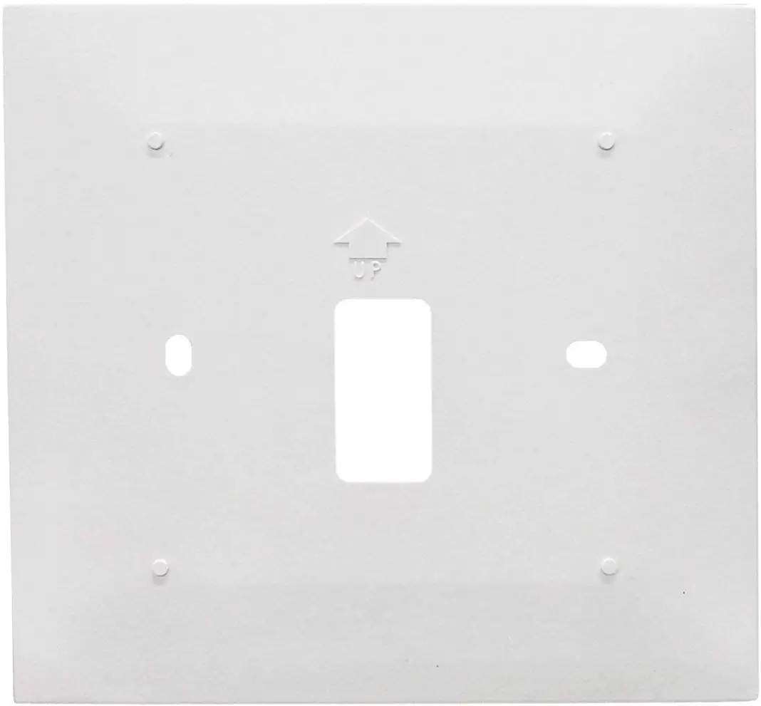
THP2400A1019 cover plate assembly.
INSTALLATION
When Installing this Product…
- Read these instructions carefully. Failure to follow them could damage the product or cause a hazardous condition.
- Check ratings given in the instructions and on the product to make sure the product is suitable for your application.
- Installer must be a trained, experienced service technician.
- After installation is complete, check out product operation as provided in these instructions.
CAUTIONElectrical HazardCan cause electrical shock or equipment damage. Disconnect power before beginning installation.
Mount Cover Plate
Mount Cover Plate Directly to Wall
- Pull the wires through the wire hole on the cover plate and wall plate.
- Position the cover plate and wall plate on the wall with the arrows pointing up. Level the wall plate for appearance only.
- Use a pencil to mark the mounting holes for your thermostat.
- Remove the cover plate and wall plate from the wall and drill two 3/16-in. holes in the wall (if drywall) as marked. For firmer material such as plaster, drill two 7/32-in. holes. Tap the wall anchors (provided with the thermostat) into the holes, until the anchor collar touches the wall.
- Pull the wires through the wire hole on the cover plate and wall plate. Position the cover plate and wall plate on the wall anchors.
- Insert the mounting screws (provided with the thermostat) into the wall anchors. Check leveling, if desired, and tighten the mounting screws.

Mount cover plate, wall plate and thermostat directly to wall.
Mount Cover Plate to a Vertical 2 in. X 4 in. Electrical Box
- Position the bracket on the electrical box. Insert two #6-32 X 5/8 flat head screws. Check leveling, if desired, and tighten the flat head screws.
- Pull the wires through the wire hole on the cover plate and wall plate. Position the cover plate and wall plate on the bracket with the arrows pointing up.
- Insert two #6-32 X 1/4 pan head screws and tighten.

Mount bracket, cover plate, wall plate and thermostat to a vertical 2 in. X 4 in. electrical box.
Mount Cover Plate to a Horizontal 2 in. X 4 in. Electrical Box
- Pull the wires through the wire hole on the cover plate and wall plate. Position the cover plate and wall plate on the electrical box with the arrows pointing up.
- Insert two #6-32 X 5/8 flat head screws. Check leveling, if desired, and tighten the flat head screws.

Mount cover plate, wall plate and thermostat to a horizontal 2 in. X 4 in. electrical box.
Resideo Technologies, Inc.1985 Douglas Drive North, Golden Valley, MN 554221-800-468-1502www.resideo.com
![]()
[xyz-ips snippet=”download-snippet”]