![]() Home
Home 
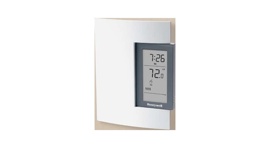
TL81007 DAY PROGRAMMABLE HYDRONIC THERMOSTAT
INSTALLATION INSTRUCTIONS
GUIDELINES
TURN OFF POWER TO THE HEATING SYSTEM AT THE MAIN POWER PANEL TO AVOID ELECTRICAL SHOCK. INSTALLATION SHOULD BE CARRIED OUT BY AN ELECTRICIAN.
- For a new installation, choose a location about 5 ft. (1.5 m) above the floor.
- The thermostat must be installed on an inside wall.
- Avoid locations where there are air drafts (top of the staircase, air outlet), dead air spots (behind a door), direct sunlight, or concealed chimneys or stovepipes.
PROCEDURE
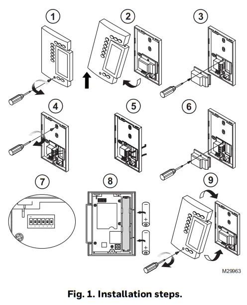
- Loosen the captive screw securing the front module to the rear module as shown in Fig. 1.
- Lift the lower part of the front module to remove it from the rear module.
- Loosen the captive screw holding the terminal cover and remove the cover.
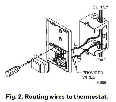
- Pass the wires through the opening to the right of the terminals. See Fig. 2. Secure the rear module to an electrical box or to the wall using the supplied wall anchors and screws.
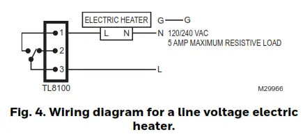
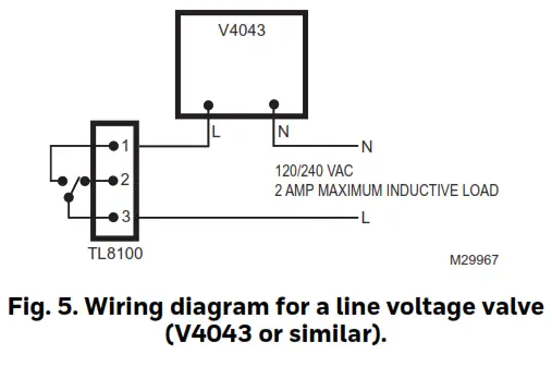
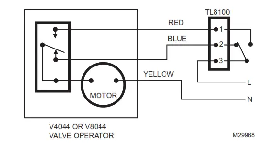
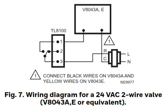
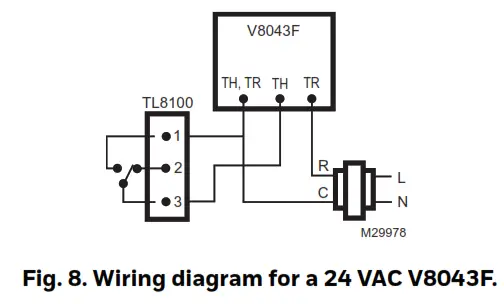
- Connect the wires (see section “Thermostat Wiring” on page 2). Use 12 AWG or smaller wire. 14 AWG is recommended for line voltage, 18 AWG is recommended for 24 VAC.
- Install the terminal cover and tighten the screw.
- Configure the thermostat using the switches located on the back of the front module (see section “Thermostat Configuration” on page 3).
- Install the batteries (see section “Power-up” on page 3).
- Mount the front module onto the rear module and tighten the screw.
 |
 |
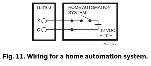
THERMOSTAT WIRING
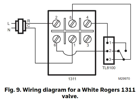
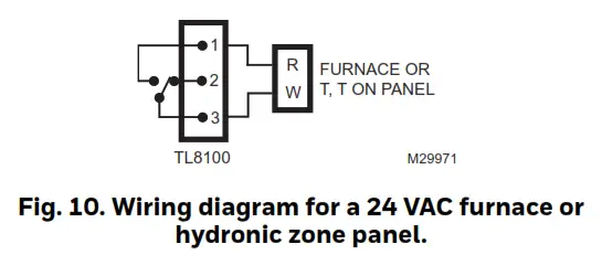 Remote Input WiringThe thermostat has an input for connecting a home automation system or a remote control system. When a signal is received at this input, the thermostat switches to Vacation mode. When the signal is removed, the thermostat returns to the original mode. See Fig. 11.
THERMOSTAT CONFIGURATION
Table 1 shows the configuration of the switches on the back of the front module. Default settings are inside the shaded cells.
Table 1.
| Switches | Description | Up |
Down |
| 1 & 2 | Cycle length (proportional)Deadband (conventional) | See Table 2 and 3. | |
| 3 | Clock display | 12H | 24H |
| 4 | Temperature display a | °F | °C |
| 5 | Temperaturecontrol mode | Proportional Mode (see“Temperature ControlMode”) | Conventional Mode(see “Temperature Control Mode”) |
| 6 | Pumpprotection b | Deactivate | Activate |
an Every time you change the temperature display format, the comfort and economy preset temperatures return to their default settings.b For hot water installations, it is recommended to enable this function to activate the pump for one minute every 24 hours to prevent pump seizure.
Temperature Control Mode
Choose proportional adaptive mode by placing switch #5 in the up position for these types of systems.
- Hot water heat systems
- Gas, oil, or electric furnaces
- Electric radiant or convection heating See Table 2 to set switches #1 and #2 for how to configure proportional adaptive mode.
Choose conventional mode by placing switch #5 in the down position for these types of systems:
- Gas or oil furnace or boiler with a 30-second or longer combustion gas prepurge cycle. To figure out the gas purging cycle of your system, measure the time-lapse from the instant the thermostat sends the heating command to the instant the burner actually goes on.
- Systems where the user desires to set how many degrees the air temperature must fall before the thermostat calls for heat. In general, the slower the HVAC system is able to distribute heat, the smaller the differential should be.
- When more than one TL8100 is wired directly to one zone valve or one zone circulator. See Table 3 to set switches #1 and #2 for how to configure conventional mode.
Table 2. Proportional Mode.
|
Cycle length |
Heating Type |
Position |
| 5 minutes (12 CPH) | For faster cycling systems |  |
| 10 minutes (6 CPH) | Fossil fuel or electric wall furnaces, electric forced air, electric radiant or convection heating | 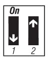 |
| 15 minutes (4 CPH) | Standard efficiency fossil fuel forced air systems or high temperature, fast response, hot water systems | ` |
| 20
minutes (3 CPH) |
High-efficiency fossil fuel systems or slow response hot water systems | 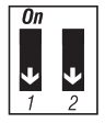 |
| Differential |
Position |
| 0.5 °F (0.3 °C) | 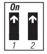 |
| 0.7 °F (0.4 °C) | 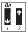 |
| 0.9 °F (0.5 °C) | 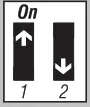 |
| 1.1 °F (0.6 °C) | 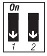 |
POWER-UP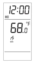
When you install the batteries, the unit performs a series of tests for a few seconds before displaying the ambient temperature.It is normal that the displayed temperature be higher than the ambient temperature if you are holding the thermostat. Once installed on the wall, the thermostat will display the true ambient temperature after one hour.
Resideo Technologies, Inc.1985 Douglas Drive North, Golden Valley, MN 554221-800-468-150269-2017EFS—05 M.S. Rev. 09-20 | Printed in United States
© 2020 Resideo Technologies, Inc. All rights reserved.The Honeywell Home trademark is used under license from Honeywell International, Inc. This product is manufactured by Resideo Technologies, Inc. and its affiliates.Tous droits réservés. La marque de commerce Honeywell Home est utilisée avec l’autorisation d’Honeywell International, Inc.Ce produit est fabriqué par Resideo Technologies, Inc. et ses sociétés affiliées.Todos los derechos reservados. La marca comercial Honeywell Home se utiliza bajo licencia de Honeywell International, Inc.Este producto es fabricado por Resideo Technologies, Inc. y sus afiliados.
[xyz-ips snippet=”download-snippet”]