Honeywell Home VNT5200E1000 Ventilation System Owner’s Manual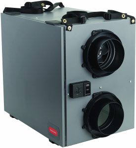
OPERATION
INCLUDED IN THIS BOX
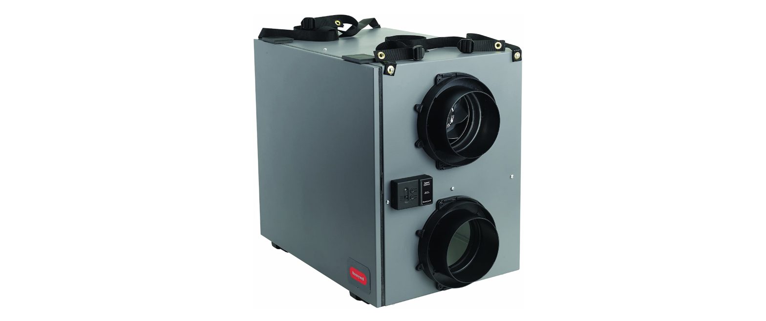
- VNT5150H1000 or VNT5150E1000

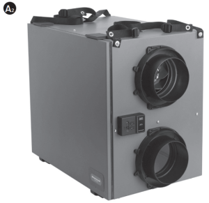
- VNT5200H1000 or VNT5200E1000
- Owner’s Guide
- Optional Controls: OPTIONAL CONTROLS SOLD SEPARATELY


 OPTIONAL CONTROLS SOLD SEPARATELY
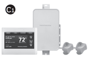
- Prestige IAQ Kit
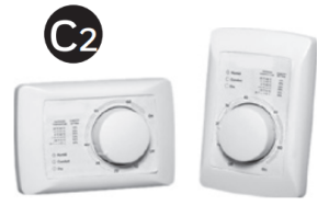
- Dehumidistat H8908
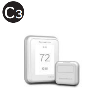
- T10 Pro Smart
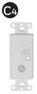
- 20/40/60 Minute Boost Control
- W8150 Ventilation Control
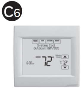
- VisionPRO Wi-Fi
Installation Checklist
Included in This BoxA1 VNT5150H1000 or VNT5150E1000A2 VNT5200H1000 or VNT5200E1000B Owner’s GuideControl Options (Sold separately)C1 Prestige IAQ KitC2 Dehumidistat H8908DC3 T10 Pro SmartC4 20/40/60 Minute Boost ControlC5 W8150 Ventilation ControlC6 VisionPRO Wi-Fi
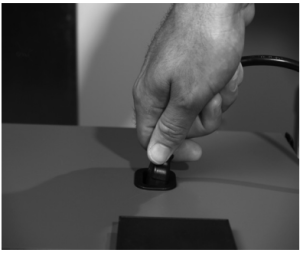
![]() Warning: Installation must be performed by a qualified service technician and must comply with local codes.Remove power to the device before installing or servicing the device. Failure to connect the device according to these instructions may result in damage to the device or the controls.
Warning: Installation must be performed by a qualified service technician and must comply with local codes.Remove power to the device before installing or servicing the device. Failure to connect the device according to these instructions may result in damage to the device or the controls.
Operation and Main Function
Your ventilation system has been engineered & designed to improve your indoor air quality by reducing during the winter time, excess humidity or other contaminants in your home and replacing this air by fresh filtered air from the outdoors. During colder seasons, the units heat recovery core (polypropylene core) will reclaim the heat from the outgoing stale air and use this heat to temper the incoming fresh air, which reduces the cost of effectively ventilating your home during winter.NOTE: Reverse process occurs in the summer months.
System Installation (examples)
- Independent System
- Exhaust at the Source and Supply in the Return
- Exhaust and Supply in the Return
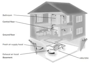

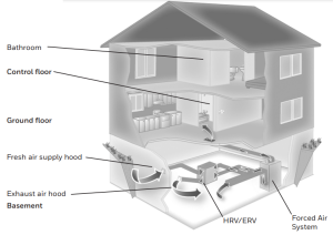
Description
Ventilation System with Recirculation ModeA. Fresh air from outsideB. Exhaust air to outsideC. Exhaust air from homeD. Fresh air to home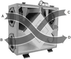
- Fresh Air from Outside Port (A): Inlet for fresh outdoor air.
- Exhaust Air to Outside Port (B): Outlet for exhausting stale, humid and contaminated air to the outdoors after transferring its heat to the recovery core.
- Exhaust Air From Home Port (C): Exhausts stale, humid and contaminated air to the outside from multiple location of the home or from the return air of the forced air system, prior to passing threw the heat recovery core.Ex: Bathroom, laundry room, etc.
- Fresh Air to Home Port (D): Introduces & distributes clean & fresh air to your home. The homes fresh air ports are normally installed in the main living areas or in the return/supply duct of the forced air system.Ex: Living room, bedrooms, recreation rooms, etc.
- Control Panel: Selects your ventilation modes (OFF, CONT or INTER), also to adjust your continuous airflow rates: Increasing (+)/ Decreasing (-).
- Synthetic Filters: Capture the largest particle and protects your heat recovery core from potential obstruction by these particles.
- Heat Recovery Core: A polypropylene cross-flow type it is designed to transfer the heat between both exhaust & supply air streams without allowing any contamination or mixing of both air streams to maximize the efficient and improve your indoor air quality.
- Condensate Drain Pan & Drainage Hose: Captures the water that accumulates during the heat transfer and defrosts sequence in the fall, winter & early spring seasons. Drain hose is connected to the drain pan and serves as drainage for the accumulation of water. It is normal during summer months to find no condensation in drain pan or in drainage hose.
- Automatic Defrost Sequence: The ERV and HRV units are equipped with an automatic defrost feature to eliminate any ice build up on the core. Automatic defrost is initiated once every hour when the fresh air supply temperature drops to 23°F (-5°C) or colder.
- The defrost cycle operates by turning off the supply fan while continuing to operate the exhaust fan.
- The exhaust fan speed is adjusted proportionally based on the outdoor temperature, initially operating at low speed.
- As the outdoor temperature continues to drop, the exhaust fan speed will increase, and will operate at maximum speed when the outdoor temperature is -4°F (-20°C) or less.
- Defrost cycle runs for 4 minutes with the supply fan off, followed by 40 minutes of continuous normal operation.
- Defrost cycles will continue to repeat as long as the temperature is 23°F (-5°C) or less
- Fresh Air from Outside Port (A): Inlet for fresh outdoor air.
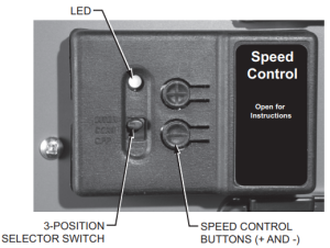
Control Panel
The control panel has a 3-position selector switch and “+” and “–” buttons for speed control. The color of the LED indicator indicates the current function of the selector switch.
- GREEN LED = Mode Control (normal operating mode)
- YELLOW LED = Balancing Control
Speed Control used as a Mode ControlWhen the LED indicator is green, the selector switch functions as a Mode Selector. The selections are:
- INTER (Intermittent): When the selector switch is in the intermittent position the unit will run only when there is a call for ventilation by any external control. At that time the unit will run on high speed until the condition is satisfied.
- CONT (Continuous): When the selector switch is in the continuous position the unit will run continuously on low speed except when there is a call for override by any control.
- OFF: When the selector switch is in the off position the unit will not operate even when there’s a call for ventilation by an external control.
- (+) and (–) buttons: Used to adjust the continuous speed setting.
Speed Control used as a Balancing ControlIn balancing mode the LED indicator is yellow, and the selector switch functions as a Balancing Control to set the high speed of the motors for balancing purposes (Fresh air, Exhaust air, and Both motors). The selections are:
- INTER: Selects the exhaust air motor.
- CONT: Selects both exhaust and fresh air motors.
- OFF: Selects the fresh air motor.NOTE: Continuous low speed is 50% of the set high speed.Speed Control used as a Motor Control
- + Button: Increase the speed of the selected motor.
- – Button: Decrease the speed of the selected motor.
Balancing Steps
NOTE: Perform the balancing steps with the HVAC equipment fan turned ON if the ERV/HRV unit is ducted into an HVAC system.
- a. Ensure that the speed control selector switch is in either the INTER or CONT position.b. Press the (+) and (–) buttons simultaneously for 5 seconds until the LED indicator light turns yellow, which indicates that you are in balancing mode.When in balancing mode, the selector switch becomes the motor selector switch. The switch positions become: INTER = Right motor (exhaust air), CONT = Both motors, and OFF = Left motor (fresh air).
- a. Use a pitot tube or flow station to measure the air flow in the fresh air duct and exhaust air duct.b. Move the mode selector switch to adjust the air flow in the duct with the higher reading.INTER: Exhaust air (right)OFF: Fresh air (left)c. Press the (+) or (–) buttons to adjust the air flow to the desired high speed setting.d. Move the mode selector switch to the CONT position (to proportionally adjust the speed of both motors at the same time.
- a. Press the (+) and (–) buttons simultaneously to exit balancing mode .b. Indicator light turns green.c. Continuous speed will be 50% of measured CFM.
Operating Your Wall Controls
Prestige™ IAQ Kit
- Controls both heating/cooling and ventilation.
- Wireless sensor for displaying outdoor temperature and humidity.
- Advanced ventilation programming includes economizing and extreme condition shutdown.
- Maintenance and service reminders.
- High definition color display.
- RedLINK™ Wireless technology

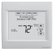
VisionPRO™ Wi-Fi (TH8321WF1001) or VisionPRO RedLINK(TH8321R1001)
- Controls both heating/cooling and ventilation.
- Ventilation programming for time of day or Ashrae standards.
- Optional ventilation lockouts for high/low temp or humidity conditions. C7089R1013 wireless outdoor sensor required for RedLINK model. Wi-Fi model uses Internet weather.
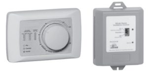
Manual Dehumidistat and Automatic Ventilation Controls
- Manual humidity control with intuitive comfort settings.
- Automatic W8150 ventilation control to ASHRAE standard, or for continuous operation.
Boost Control Digital Timer
- Ventilation boost control for 20/40/60 minutes.
Troubleshooting
![]() CAUTION: Servicing the ERV/HRV unit with its electrical circuitry can cause personal injury. Always make sure that power to the unit is disconnected prior to making any connections. Failure to disconnect the power could result in electrical shock. Service should only be performed by a qualified service technician.
CAUTION: Servicing the ERV/HRV unit with its electrical circuitry can cause personal injury. Always make sure that power to the unit is disconnected prior to making any connections. Failure to disconnect the power could result in electrical shock. Service should only be performed by a qualified service technician.
|
Problem |
Recommended Troubleshooting Steps |
|
ERV/HRV unit not running |
|
|
Air is too dry |
|
|
Air too humid |
|
|
LED on control panel remains green |
If the LED light on the ERV/HRV control panel remains green. the motors do not energize. and the controls do not operate. This can indicate that the Polarization in the main AC outlet is inverted |
Maintenance of Your HRV/ERV
Quarterly or as Needed
- Filters.Four times per year or as needed, vacuum the filters. Replace filters as needed.
Annually or as Needed
- Inside the Unit.Once a year or as needed, clean the interior of the unit (walls and drain pan) with a mild and non abrasive soap. It is recommended to use products that are environmentally-friendly.
- Energy Recovery Core Unit (VNT5150E1000 and VNT5200E1000)Vacuum the ERV core or rinse with cold water. Do not use soap, dishwasher, or a pressure washer.
- Heat Recovery Core Unit (VNT5150H1000 and VNT5200H1000)Once a year or as needed, vacuum the four surfaces, let soak in warm water and mild soap for 15 minutes, then spray rinse and let dry.
NOTE: See Cleaning Steps on page 11 for the above maintenance items.
Cleaning Steps
- Disconnect the AC power from the unit or the wall.
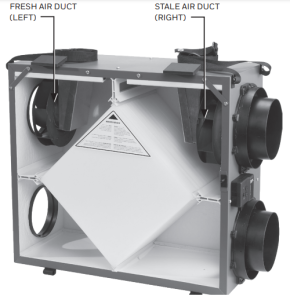
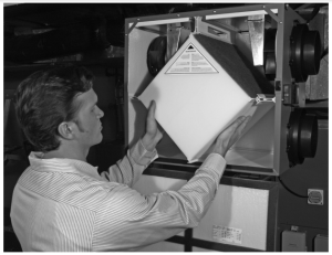
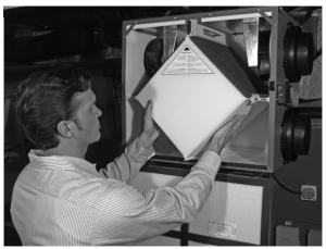
- Open the side door panel by opening the two latches on the top of the side panel and lowering the panel to its fully open position Remove both filters from the top left and right sides of the Core, then vacuum both filters. Slide out the Core, and clean according to the instructions on the previous page.
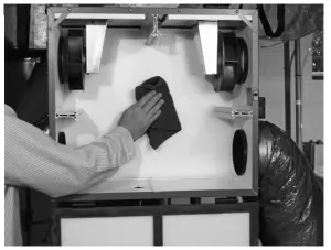
- Clean inside of unit with a damp cloth and wipe dry when finished.
- Replace the Core and the two filters, re-latch the side panel, then reconnect the AC power to the unit.
5-Year Limited Warranty
Resideo warrants this product, excluding maintenance items such as the filter, to be free from defects in workmanship or materials, under normal use and service, for a period of five (5) years from the date of first purchase by the original purchaser. If at any time during the warranty period the product is determined to be defective due to workmanship or materials, Resideo shall repair or replace it (at Resideo’s option).
If the product is defective,(i) return it, with a bill of sale or other dated proof of purchase, to the place from which you purchased it; or(ii) call Resideo Customer Care at 1-800-468-1502. Customer Care will make the determination whether the product should be returned to the following address: Resideo Return Goods, 1985 Douglas Dr. N., Golden Valley, MN 55422, or whether a replacement product can be sent to you.
This warranty does not cover removal or reinstallation costs. This warranty shall not apply if it is shown by Resideo that the defect was caused by damage which occurred while the product was in the possession of a consumer.
Resideo’s sole responsibility shall be to repair or replace the product within the terms stated above. RESIDEO SHALL NOT BE LIABLE FOR ANY LOSS OR DAMAGE OF ANY KIND, INCLUDING ANY INCIDENTAL OR CONSEQUENTIAL DAMAGES RESULTING, DIRECTLY OR INDIRECTLY, FROM ANY BREACH OF ANY WARRANTY, EXPRESS OR IMPLIED, OR ANY OTHER FAILURE OF THIS PRODUCT. Some states do not allow the exclusion or limitation of incidental or consequential damages, so this limitation may not apply to you.
THIS WARRANTY IS THE ONLY EXPRESS WARRANTY RESIDEO MAKES ON THIS PRODUCT. THE DURATION OF ANY IMPLIED WARRANTIES, INCLUDING THE WARRANTIES OF MERCHANTABILITY AND FITNESS FOR A PARTICULAR PURPOSE, IS HEREBY LIMITED TO THE FIVE YEAR DURATION OF THIS WARRANTY. Some states do not allow limitations on how long an implied warranty lasts, so the above limitation may not apply to you.
This warranty gives you specific legal rights, and you may have other rights which vary from state to state.
If you have any questions concerning this warranty, please write Resideo Customer Care, 1985 Douglas Dr, Golden Valley, MN 55422 or call 1-800-468-1502.
Standards and Certifications:CSA-22.2 #113-10, CSA 439 StandardUL Standard 1812RoHS CompliantHVI CertifiedFCC Part 15, Class BENERGY STAR (VNT6150H1000 & VNT6200H1000)Install the ERV/HRV Ventilation System according to national and local regulations, building, and safety codes.

 http://www.resideo.com/Resideo Inc., 1985 Douglas Drive North,Golden Valley, MN 554221-800-468-150269-2481EF—07 M.S. Rev. 05-21 | Printed in United States.
 Ventilation System
[xyz-ips snippet=”download-snippet”]