Honeywell 5800RPS Wireless Roller Plunger Switch
Installation Instructions
General Information
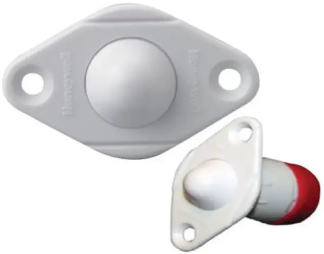
The 5800RPS Wireless Roller Plunger Switch is a plunger switch contact that provides concealed protection for doors. It is intended for use only with alarm systems that support Honeywell 5800 series devices. The transmitter is powered by a long-life lithium battery that is easily replaceable when a low battery condition is indicated by the control.
Programming the ID Number
Each 5800RPS has its own unique serial number permanently assigned during manufacturing. The serial number is located on the label attached to the antenna. This should never be removed. The control panel is used to “enroll” the transmitter’s ID during installation of the alarm system. The zone input type should be as “RF” (i.e. Supervised “RF”) type.Refer to the control panel’s installation instructions for further details.
Preliminary Considerations
DOORS:
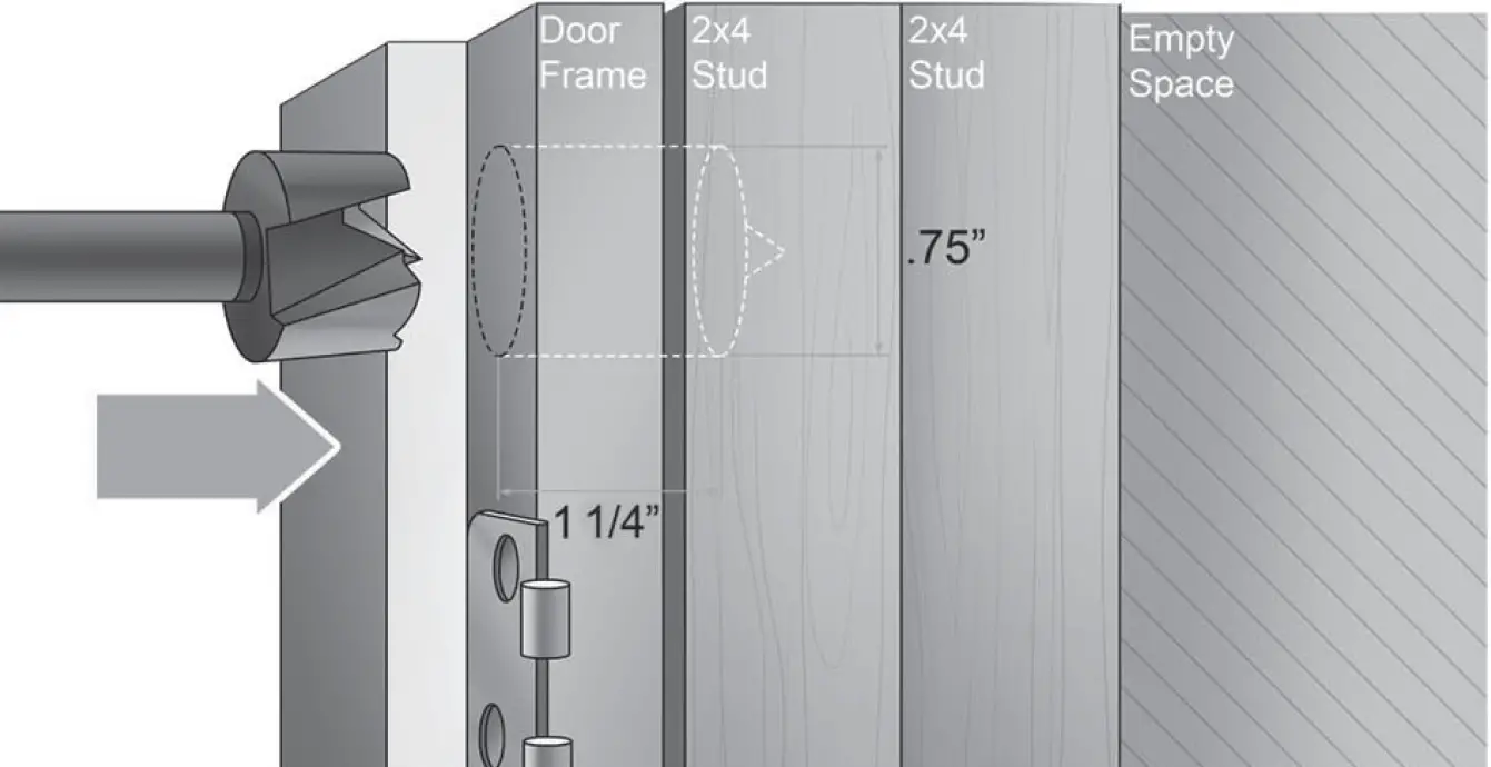
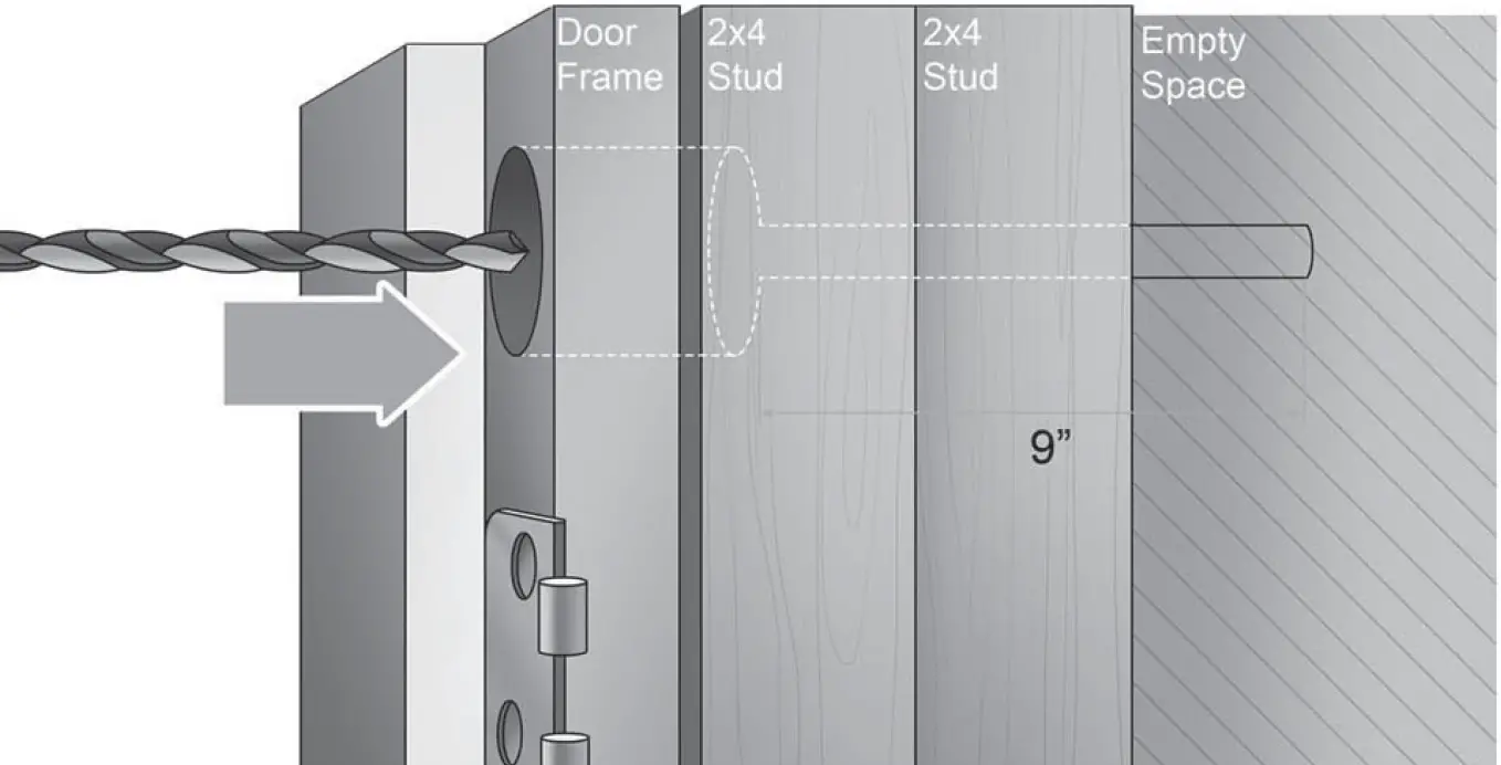
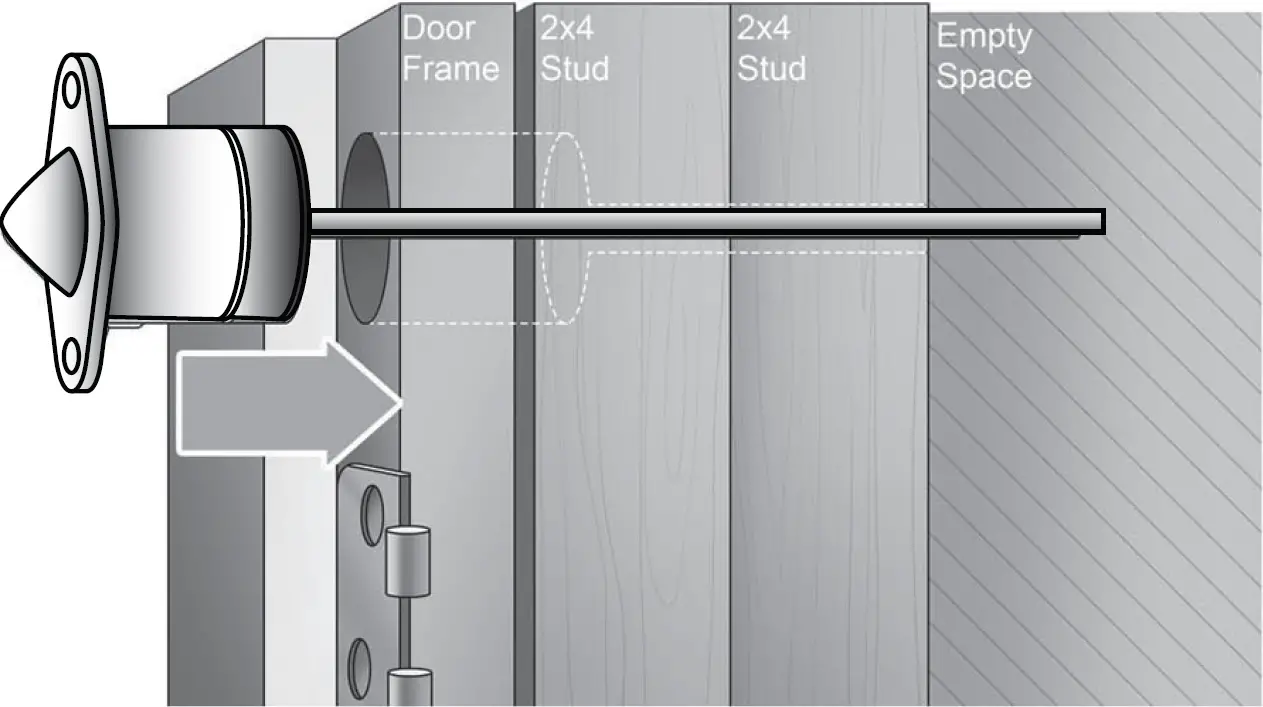
- A 3/4″ hole is drilled into the door frame on the hinge side, at least 4 feet above the floor, and should be 1 1/4″ deep. A second smaller hole of 1/4″ diameter can be drilled from the center of the first hole further into the frame to accommodate the wire antenna or insert the antenna into the space between the door frame and the stud framing.The length of the 1/4″ diameter hole should be long enough to accommodate the wire antenna without bending. The unit may still operate if the antenna is bent, however the range will be reduced, and should be verified. A plastic antenna guide is included as an aid for the installer, and can be inserted into the 1/4″ hole if need be.
- Before drilling any holes, tape the transmitter in its approximate location (with battery installed as described under BATTERY INSTALLATION / REPLACEMENT; see page back) and conduct Go/No Go tests (see control’s instructions) to verify adequate signal strength. Relocate the transmitter if necessary.
NOTE: THE 5800RPS IS NOT RECOMMENDED TO BE USED ON WINDOWS, AS IT WOULD REQUIRE A HOLE DRILLED THROUGH BOTH THE INNER AND OUTERSKIN OF THE FRAME THUS CREATING THE POSSIBILITY OF WATER INGRESS AND DAMAGE.
Step 01: Measure and Drill for PlungerUse a 3/4″ drill bit to drill into the door jam to a 1 1/4″ depth.
Step 02: Drill for AntennaA 1/4″ hole must now be drilled in the center of the cavity through the door jamb. This is so the antenna can be inserted through the door jamb frame and the supporting studs.
Step 03: Slide on StrawSlide the antenna into supplied antenna guide (straw).

Step 04: Place and SetInsert Switch and Antenna into the door jamb.
MOUNTING
- Mark the selected location for the transmitter on the “hinge side” of the door frame at least 4′ above the floor.

- Before drilling any holes, make sure that the successful Go/No Go transmission tests have been conducted.
- Drill hole at the location marked for the transmitter (3/4″ diameter, at least 1-1/4″ in depth).
- Drill a second hole (1/4″ in diameter, at least 8″ in depth) at the center of the first hole for antenna insertion or insert the antenna into the space between the door frame and the stud framing.
- Insert the antenna into the provided straw. This is to make the installation easy and ensure the antenna will remain straight. Never coil or bunch up the antenna.
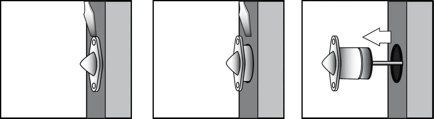
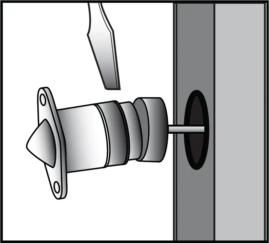
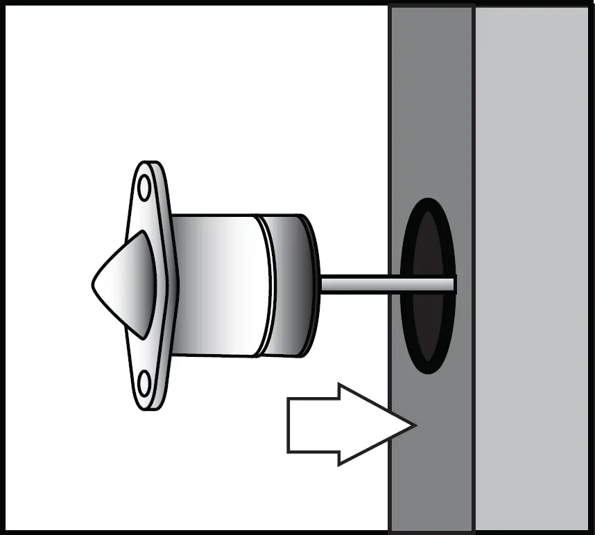
- Insert the transmitter and antenna assembly into the hole so that the transmitter flange is flush with the surface of the door frame.DO NOT hammer the transmitter into place with hard blows. Press into place either by hand or simply by closing the door, which presses it into place.
- Secure the transmitter by installing the two screws provided.
SPECIFICATIONS
| 5800MICRA transmitters | ||
| Dimensions
Power Source Temperature Range |
Dowel Package | 0.750″ diameter |
| Additional Info | Dowel Lid 0.850″ diameter x 0.060″ thick | |
| Wire Antenna | 8″ x 1/8″ flexible antenna extends from sensor | |
| Fits Cavity Depth | 1.00″ depth | |
| 3.0V Lithium Coin Cell Battery CR1620 | ||
| 10º to 120º F (-12º to 49º C) | ||
| Compatibility | Doors | Wood and Metal Frame |
| Note: Range may be reduced if used in metal frame doors. | ||
| FCC Notice | This device complies with FCC Rules part 15. Operation is subject to the following two conditions:
The user shall not make any changes or modifications to the equipment unless authorized by the Installation Instructions OR User Manual.Unauthorized changes or modifications could void the user’s authority to operate the equipment. |
BATTERY INSTALLATION & REPLACEMENT
- Remove the transmitter from the door frame by removing the two screws from the flange and prying the unit from the hole using the flat blade of a small screwdriver. The transmitter must be removed from the door completely in order to refit the unit back into the hole once the internal battery has been replaced.
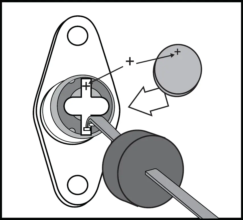
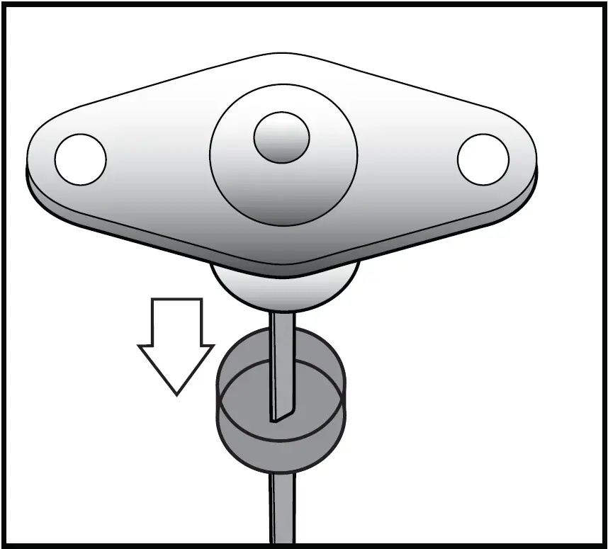
- Using the flat blade of a small screwdriver separate the transmitter assembly from the base with a slight counter-clockwise twist. Once open, slide the cap with the transmitter PC board assembly apart from the base. Pull the antenna through the hole in the base just enough to allow the battery to be replaced. Do not pull the antenna completely out of the base.
- Carefully remove the old battery from its battery holder on the bottom of the PC board
- Observe correct polarity (see Figure 3 Step 3 & 4) and insert the fresh battery into the battery holder (positive polarity is shown on the battery holder). Always use Energizer or Panasonic brand batteries.
- Slide the transmitter assembly back into its base by gently pulling on the antenna, easing the assembly into place.
- Snap the cap back onto the base, locking it into place.
- Placing the antenna into the cavity first, reinsert the unit into its original mounting hole in the door frame and secure the flange using the two screws previously removed.
TO THE INSTALLER
Regular maintenance and inspection (at least annually) by the installer and frequent testing by the user are vital to the continuous satisfactory operation of any alarm system. The installer should assume the responsibility of developing and offering a regular maintenance program to the user, as well as acquainting the user with the proper operation and limitations of the alarm system and its component parts. Recommendations must be included for a specific program of frequent testing (at least weekly) to insure the system’s operation at all times.REFER TO THE lNSTALLATION INSTRUCTIONS FOR THE RECEIVER / CONTROL WITH WHICH THIS DEVICE IS USED FOR DETAILS REGARDING LIMITATIONS OF THE ENTIRE ALARM SYSTEM.FOR WARRANTY INFORMATION, PLEASE GO TO: www.security.honeywellhome.com/warranty
2 Corporate Center Drive, Suite 100P.O. Box 9040, Melville, NY 11747© 2020 Resideo Technologies, Inc.www.resideo.com
 report this ad
![]()
[xyz-ips snippet=”download-snippet”]