
![]()
FA-300/FA-324 Alarm Bar
User’s Guide
Rev. BMarch 2019P/N F05-4032-000
© Copyright 2019 Honeywell International
Read Before Operating
This manual must be carefully read by all individuals who have or will have the responsibility of using, maintaining, or servicing this product. The product will perform as designed only if it is used, maintained, and serviced in accordance with the manufacturer’s instructions. The user should understand how to set the correct parameters and interpret the obtained results.
CAUTION!
To reduce the risk of electric shock, turn the power off before opening this instrument or performing service. Never operate the instrument when the instrument is open. Use and service this product only in an area known to be non-hazardous.
Proper Product Disposal At End Of Life

EU Directive 2012/19/EU: Waste Electrical and Electronic Equipment (WEEE) This symbol indicates that the product must not be disposed of as general industrial or domestic waste. This product should be disposed of through suitable WEEE disposal facilities. For more information about disposal of this product, contact your local authority, distributor, or the manufacturer.
4
WARNINGS
Use only in non-hazardous locations.
For safety reasons, this equipment must be operated and serviced by qualified personnel only. Read and understand instruction manual completely before operating or servicing.
5
1 Standard Contents
- FA-300/FA-324 Alarm Bar
- Integral 10-meter (33-foot) connection cable
- User’s Guide
2 General Information
The FA-300 Alarm Bar works with the RAE Systems FMC2000 controller (12 Volt) and other compatible devices. The FA-324 Alarm Bar works with the Honeywell TouchPoint Plus Wireless Controller (24 Volt). Both models provide bright visible and loud audible notification when a controller is in alarm.
2.1 Key Features
- Loud siren: 117dB @ 3 m (10′)
- Four bright strobe lights with impact-resistant polycarbonate lenses (red, white, blue, amber)
- Second port for interconnection with second controller
- Low maintenance
6
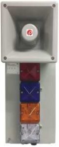
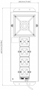
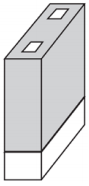
3 Physical Description
The FA-300/FA-324 Alarm Bar comes pre-assembled and requires only connection via its integrated cord to a controller with relays. It has mounting flanges at the top and bottom with four holes that accept screws for attaching the FA-300/FA-324 Alarm Bar to a wall or other flat surface. It receives all power from the controller that it is attached to, simplifying installation and maintenance.
Front View Side View

7
4 Installation
4.1 Mounting the FA-300/FA-324 Alarm Bar
The FA-300/FA-324 Alarm Bar is designed to be wallmounted and has four holes for anchoring the FA-300/FA324 Alarm Bar, using screws or bolts.
Before mounting the FA-300/FA-324 Alarm Bar, make sure that its cord can reach the controller that it will be electrically connected to.
Make sure that there is approximately 12″ (30 cm) of clearance on all sides of the FA-300/FA-324 Alarm Bar so that the siren’s sound is not attenuated and to ensure clear view of the four visible alarm lights.
Follow these steps:
- Locate the FA-300/FA-324 Alarm Bar on a wall or other flat surface and mark the four holes’ locations.
- Remove the FA-300/FA-324 Alarm Bar.
- Drill the four holes.
- Hold the FA-300/FA-324 Alarm Bar firmly against the wall and insert and tighten the screws.
The FA-300/FA-324 Alarm Bar is now ready to be connected to the controller.
8
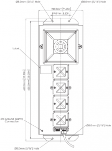
4.2 Drilling Chart
When mounting the FA-300 on a wall, make sure to use heavy-duty steel screws spaced as indicated below.
9
4.3 Electrical/Control Connections
The FA-300/FA-324 Alarm Bar has a 33’ (10 m) cable with a screw-type multi-pin connector. It is designed to mate with the connector on a RAE Systems FMC2000 or TouchPoint Plus Wireless Controller and some similar controllers that use the same connector type and relay configuration.
10
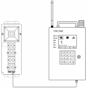
4.4 Connecting to An FMC2000 Controller
The FMC2000 has a female 6-pin connector on the bottom that is designed for connection with a RAE Systems FA-300 Alarm Bar.
Note: The internal wires from the FMC2000 connector are pre-wired to the NO (Normally Open) connection points on the five relay wiring blocks. Refer to the FMC2000 User’s Guide for details of wiring for other configurations, including NC (normally closed) and other alarm orders.
Note: Pin F connects to Ground. Pins B, C, D, and E transmit 12V @ 2A power when an alarm occurs.
Connector Pin Layout
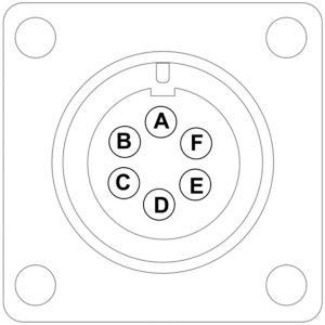
FMC2000 Connector Pinout
Pin A: No connectionPin B: Power switch for red lightPin C: Power switch for blue lightPin D: Power switch for amber lightPin E: Power switch for white lightPin F: Ground
Note: If a second Alarmbar is not connected to the auxiliary port on the FA-300/FA-324 Alarm Bar, keep the dust cap on the connector to protect the pins.
11
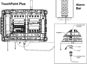
4.5 Connecting to A TouchPoint Plus Wireless Controller
Two cables are used for connecting a TouchPoint Plus Wireless Controller and an Alarm Bar.
Important!Before making any connections, first make sure that Touchpoint Wireless is powered off.
- Connect the FA-324 Connector Cable 1 shown on page 11 by following the steps detailed in the drawings.
- Connect the FA-324 Connector Cable 2 shown on page 14 by following the steps detailed in the drawings.
- To anchor the FA-324 Connector Cable 2’s end (female type) to the Touchpoint Plus enclosure, first remove a plug from one cable entry.
- Fix the FA-324 Connector Cable 2 to the enclosure.
- Connect FA324 Cable’s end (male type) to the enclosure and fasten its nut
12
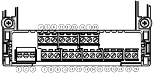
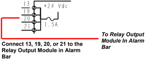
Main Module, Cable 1
| Terminal | Label | Channel |
| 13 | +24VDC | External Alarm Power |
| 19 | +24VDC | External Alarm Power |
| 20 | +24VDC | External Alarm Power |
| 21 | +24VDC | External Alarm Power |

13
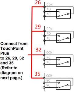
Relay Output Module, Cable 1
| Terminal | Label | Channel |
| 25 | NC | Relay 9 |
| 26 | COM | |
| 27 | NO | |
| 28 | NC | Relay 10 |
| 29 | COM | |
| 30 | NO | |
| 31 | NC | Relay 11 |
| 32 | COM | |
| 33 | NO | |
| 34 | NC | Relay 12 |
| 35 | COM | |
| 36 | NO |
14
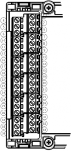
Relay Output Module
15
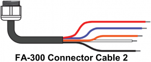
Main Module, Cable 2
| Pin | 20AWG Wire Color |
| 1 | NC |
| 2 | Red |
| 3 | Blue |
| 4 | Orange |
| 5 | White |
| 6 | Black |
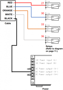
Relay Output Module, Cable 2
| Terminal | Label | Channel |
| 25 | NC | Relay 9 |
| 26 | COM | |
| 27 | NO | |
| 28 | NC | Relay 10 |
| 29 | COM | |
| 30 | NO | |
| 31 | NC | Relay 11 |
| 32 | COM | |
| 33 | NO | |
| 34 | NC | Relay 12 |
| 35 | COM | |
| 36 | NO |
16
17
5 Maintenance
No periodic maintenance is required for the FA-300/ FA-324 Alarm Bar. Check occasionally that the cable is securely fastened and shows no sign of damage. Also check that the polycarbonate lenses are tightly fastened to the bases of the strobe lights and have no cracks. If they are damaged, they should be replaced.
18
6 Specifications
| Size | 9.45″ x 26.98″ x 8.52″ (66 cm x 24 cm x 31.65 cm), including siren horn |
| Weight | 16.35 lbs (7.42 kg), including cable |
| Enclosure material | Stainless steel light bases with polycarbonate lens covers; ABS siren horn |
| Audible alarm | 117dB @ 3 m (10′) |
| Visual alarms | Four super-bright xenon strobe lights with polycarbonate lens covers (red, white, blue, amber) |
| Flash rate | 1 flash per second |
| Primary Input | Permanently affixed cable with 6-pin male connector |
| Secondary Input | 6-pin male connector |
| Cable Length | 33′ (10 m) |
| Power Supply | FA-300 Powered by 12-volt 2A outputs from controller FA-324 Powered by 24-volt 2A outputs from controller |
| Operating Temperature | -13° F to +131° F (-25° C to +55° C) |
19
Special Servicing NoteIf the instrument needs to be serviced, contact either: The Honeywell distributor from whom the instrument was purchased; they will return the instrument on your behalf.
or
The Honeywell RAE SystemsTechnical Service Department. Before returning the instrument for service or repair, obtain a Returned Material Authorization (RMA) number for proper tracking of your equipment. This number needs to be on all documentation and posted on the outside of the box in which the instrument is returned for service or upgrade. Packages without RMA Numbers will be refused at the factory.
20
7 Troubleshooting
| Problem |
Possible Reasons & Solutions |
| Siren inoperative | Reasons: Wiring problem.
Alarm level set too low at controller.
Solutions: Make sure cable is connected to controller. Make sure cable is not damaged. Check siren horn for obstruction. Test relay in controller. |
| Strobe light inoperative | Reasons: Wiring problem.
Alarm level set too low at controller. Strobe light is damaged.
Solutions: Make sure cable is connected to controller. Make sure cable is not damaged. Check siren horn for obstruction. Test relay in controller. Call Technical Support at +1 408-752-0723 or toll-free at +1 888-723-4800 |
| Wrong strobe light during alarm | Reasons: Relay wiring problem.
Reasons: Check that correct relay is wired to appropriate strobe light. |
21
7.1 Checking FMC2000 Relay Continuity
Each relay in an FMC2000 controller has a common terminal and a normally open (NO) and normally closed (NC) terminal. If you think the wiring to the FA-300/FA-324 Alarm Bar is correct and that the FA-300/FA-324 Alarm Bar is in working order, but that an alarm signal is not being passed to it, check the relays in the FMC2000 controller. Use a continuity tester or voltmeter (set to measure resistance) to check the relay’s activity.
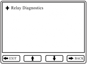
1. Enter the Relay Diagnostic menu. Press Enter, followed by the password (the default is 123456).
2. Touch the probes of a continuity tester or voltmeter to the NO and COM terminals on the relay’s relay block inside the FMC2000.

Testing continuity of Normally Open portion of relay.

Testing continuity of Normally Closed portion of relay.
22
3. In the Relay Diagnostic menu, toggle the relay by pressing the keypad’s corresponding key (1, 2, 3, 4. 5).
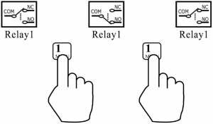
4. Touch the probes to the NC and COM terminals on the relay block.5. Again, toggle the relay by pressing the corresponding key on the keypad.
Each time you press the key, the continuity tester or voltmeter should show that the relay has changed from open to closed (or vice versa). If this change does not occur, then the relay may be damaged and require replacement. Contact Honeywell RAE Systems Customer Support.
23
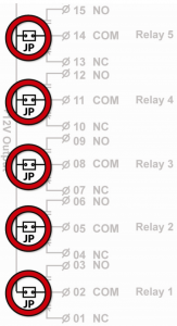
Note: Make sure the jumpers (marked JP for each of the five relays) are in place on the printed circuit board that includes the five alarm relay connection blocks in the FMC2000. If any of the jumpers is missing, the relay is in “dry contact” configuration, and no voltage reaches the relay connection blocks.
![]()
24
![]()
For more informationwww.honeywellanalytics.comwww.raesystems.com
Europe, Middle East, AfricaLife Safety Distribution GmbHTel: 00800 333 222 44 (Freephone number)Tel: +41 44 943 4380 (Alternative number)Fax: 00800 333 222 55Middle East Tel: +971 4 450 5800(Fixed Gas Detection)Middle East Tel: +971 4 450 5852(Portable Gas Detection)[email protected]
AmericasHoneywell Analytics Distribution Inc.Tel: +1 847 955 8200Toll free: +1 800 538 0363Fax: +1 847 955 8210[email protected]
RAE Systems by HoneywellPhone: 408.952.8200Toll Free: 1.888.723.4800Fax: 408.952.8480
Asia PacificHoneywell Analytics Asia PacificTel: +82 (0) 2 6909 0300Fax: +82 (0) 2 2025 0328India Tel: +91 124 4752700[email protected]
Technical ServicesEMEA: [email protected]US: [email protected]AP: [email protected]
Rev. BMarch 2019P/N F05-4032-000
References
[xyz-ips snippet=”download-snippet”]