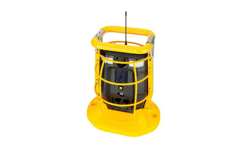

BW™ RigRat I.S. BarrierInstallation Guide
The following instructions cover installation and wiring the BW RigRat I.S. Barrier. This equipment should only be connected in accordance with applicable regulations by qualified personnel.
Honeywell BW RigRat I.S. Barrier Installation Guide
Step 1
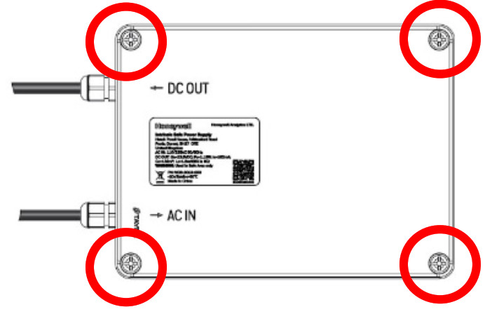
Remove the four screws holding the cover in place, and then lift off the cover.
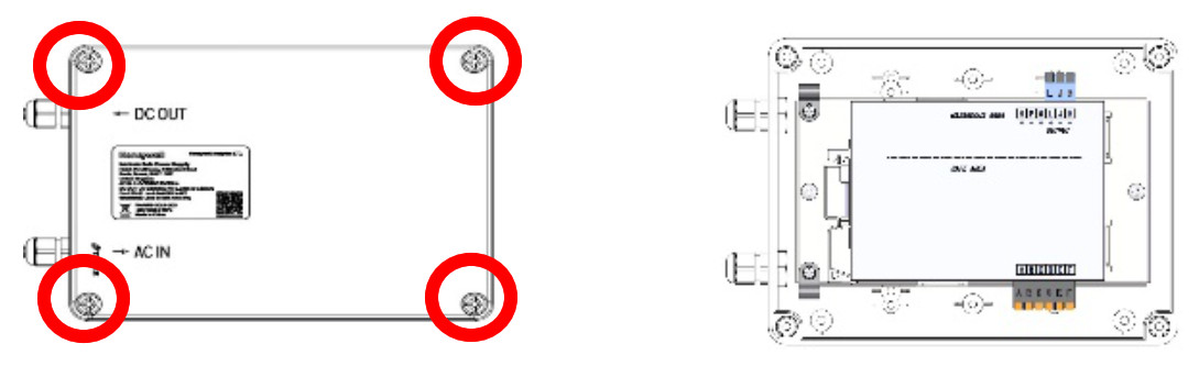
Step 2
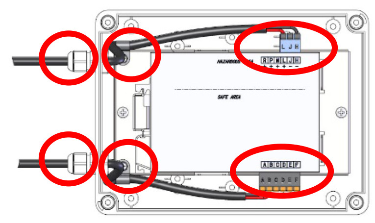
Pull out the input and output connectors.
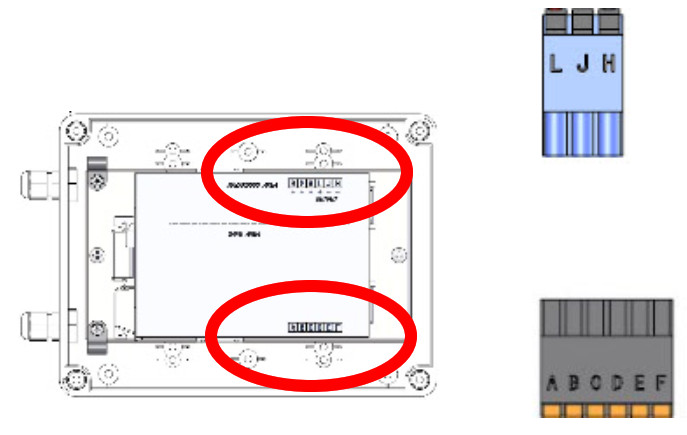
Step 3
Pass wires through the glands on the exterior of the case and then connect the wires to their terminals on each connector,
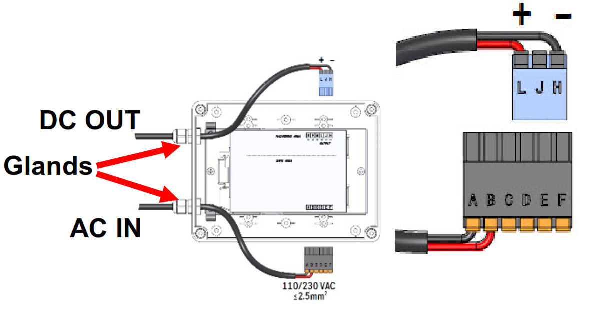
Step 4
Plug connectors back into the barrier. Then secure the wires. And tighten the glands.
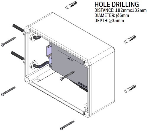
Step 5.1Mounting on concrete or brick wall before or after wiring.
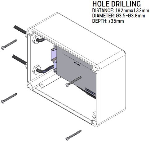
Step 5.2Mounting on wooden wall before or after wiring.
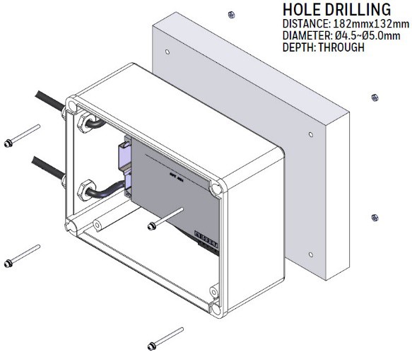
Step 5.3Mounting on sheet or plate metal (<30mm thick).
Step 6
Secure the back cover by tightening the four screws.
Download The BW RigRat User’s GuideThe BW RigRat User’s Guide should be read and understood before installing or using the BW RigRat I.S. Barrier. It is available at: safety.honeywell.com

http://www.safety.honeywell.com
Read and understand all the instructions in the BW RigRat User’s Guide before you start install.
These equipment items may receive hazardous voltages on their terminals. If you do not follow the instructions correctly, you may expose yourself and others to serious injury as well as damage to equipment. Before starting your installation, ensure that the model and power supply are suited to your purpose. This equipment should only be connected in accordance with applicable regulations by qualified personnel.
- Connection• Standard: plug-in cage clamp terminals (max. capacity 2.5 mm2)• A flat head screwdriver (0.6 x 3.5 mm) is recommended to open the cage clamp terminal• Optional: plug-in screw terminals (max. capacity 2.5 mm2)
- InstallationThe equipment is intended for association in accordance with intrinsic safety; the installation mustbe in compliance with standard EN 60079-14, in particular paragraph 12.
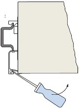
- Fixing and mountingThe equipment is intended for installation on an EN 50022 rail attached horizontally on a vertical plane, in order to respect the direction of natural convection.Do not obstruct the air vents. Use a screwdriver to insert and remove the equipment as indicated.
- LocationThe equipment must be installed in a non-explosive atmosphere, in a safe environment free of condensation and corrosive or conductive dust. Intrinsic safety is ensured in the operating temperature range specified in paragraph 1.6. However, you should remember that the service life of electronic equipment is reduced by half when its temperature is increased by 10° C.You should therefore install the equipment in suitably ventilated equipment rooms, avoid the proximity of elements that may heat the equipment by radiation or which are likely to generate electromagnetic radiation greater than 10V/m.
- Electrical connectionElectrical connections must be made when the equipment is DE-ENERGIZED, using wires with a maximum diameter of 2.5 mm2. For connections, refer to the wiring diagram.
- Mechanical propertiesThe intrinsic safety terminals must only be connected to intrinsic safety equipment or equipment that is in compliance with paragraph 5.7 of standard EN 60079-11. Moreover, the association of equipment and the connection cable must be compatible in terms of intrinsic safety.
- Cable pathThe properties of cables and their routing from the ATEX zone (I.S. cables) must comply with the recommendations set out in paragraphs 6.1, 6.2.1, and 6.3 of standard EN 600079-11.Full precautions must be taken to prevent electromagnetic disturbance with other cables that maygenerate dangerous voltages or currents. The I.S. cables must be clamped in order to prevent random contact with other cables in the event the terminal is cut or damaged.
- Adjustments and configurationSee technical data sheet or instructions for use.
- MaintenancePrecautions to take during maintenance. Unmounting must be carried out DE-ENERGIZED.In the event you suspect a failure or permanent fault, return the equipment to our services or representatives, who are the only maintenance providers certified to perform expert assessments or repairs.
- Un-mountingUn-mount the unit from the enclosure by using a screwdriver as shown.
References
[xyz-ips snippet=”download-snippet”]