![]() CM701PROGRAMMABLE THERMOSTAT
CM701PROGRAMMABLE THERMOSTAT

This is a legacy product document supported by Resideo. It is no longer manufactured
PRODUCT SPECIFICATION SHEET
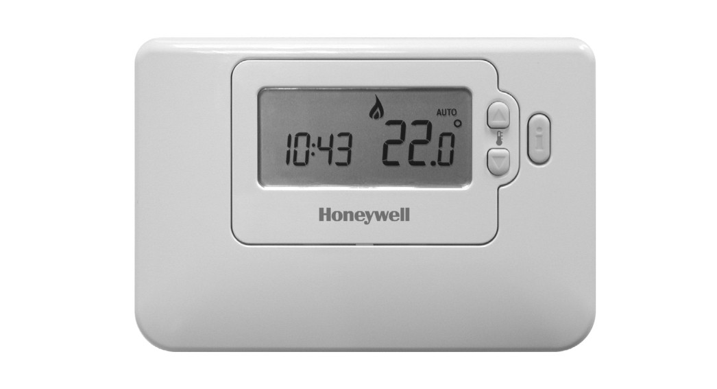
The CM701 thermostat is designed to provide automatic time and temperature control of heating systems in villas and apartments.It can be used as part of a system in conjunction with combi boilers, oil-burners and gas-fired boilers, circulation pumps, thermal actuators, zone valves and electric heat systems (<5A).The CM701 is designed with the installer in mind and includes a molded back-plate with trunking guides and wiring breakouts to make installation quick and easy.The CM701 large LCD display, button layout based on the same simple programming philosophy used on our acclaimed CM20 products and the introduction of an ‘OK’ button makes it easier to install and more user-friendly.The unit is ideal for consumers who want reliable precise temperature control from a modern looking, simple to program, and easy to use the product.
FEATURES
- Attractive slim, modern styling makes it ideal for location in any type of home.
- 24-hour heating program.
- Up to 4 daily independent time and temperature level changes let you set 4 time and temperatures pairs to suit your lifestyle.
- Temporary programmed temperature override to temporarily override the programmed temperature till the next switch point.
- Room Temperature Enquiry.
- EEPROM memory holds the user program indefinitely.
- The OFF mode has an integral frost protection setting at a minimum 5°C (installer adjustable) so that pipes in the house will never freeze in winter.
- 24…230V 5A resistive, 2A inductive SPDT relay provides compatibility with most domestic central heating systems reducing the need to stock many different models.
- Battery-powered by 2 x AA size (LR6) alkaline cells.
- Minimum battery life of 2 years with low battery warning indicator.
- Built-in default heating program.
- Surface or wall box mounting options, with trunking guides and wiring breakouts to simplify installation.
- No installer links or special installer switches on the back of the unit mean no adjustment is required for combi boilers and most domestic central heating systems.
- User Set-Up Mode allows extra functions to be set at the discretion of the user:
- AM-PM or 24hr time display.
- Resetting the heating profile to factory default.
- Installer Set-Up Mode allows extra functions to be set at the discretion of the installer to match the consumer’s applications and needs:
- Pump Exercise.
- Upper / Lower Setpoint Limit Adjust.
- Temperature offset.
- Minimum ON time.
- Cycle rate.
- Proportional Band Width.
- Diagnostic Mode to assist in faultfinding.
CONTROLS / DISPLAY LAYOUT
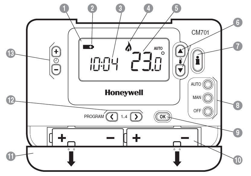
PRODUCT LAYOUT:
| 1. LCD Screen2. Battery Low Indicator3. Time Display4. Burner On Indicator5. Temperature Display6. Temperature Change Buttons7. Information Enquiry Button | 8. Operating Mode Buttons9. Green OK Button10. Battery Compartment11. Battery Cover12. Program Buttons13. Time Change Buttons |
SPECIFICATIONS
| Batteries :Battery life:Battery replacement :Switch type:Electrical rating: Time display :Time keeping accuracy :Program :Time setting resolution :Sensing element :Temperature setting range : | 2 x 1.5 V IEC LR6 (AA) Alkaline cellsMinimum 2 yearsProgram retained in EEPROMSPDT (potential free)230 V~, 50…60 Hz, 0.1 A to 5 A resistive 0.1 A to 2 A inductive (0.6 pf) 24 V~, 50…60 Hz, 0.5 A to 5 A resistive 0.5 A to 2 A inductive (0.6 pf)24 hour or 12 hour AM/PM formatTypically better than 10 minutes per year4 daily time and temperature level changesTime of day – 1 minute , Program – 10-minute steps100K (@ 25 oC ) NTC thermistorProgram: 5 to 35 o C in 0.5 o C steps Frost o: 5 C or equal to ower limit o (5 C to 21 o C). |
| Temperature control accuracy | ±0.5 K (nominal) @ 20 o C, 50% load 3 K ∆/hour |
| Room Temperature display range | From 0 o C to 50 o C |
| Control form | P + I (Proportional + Integral) |
| Minimum ON time | 10% of cycle time (min one minute), adjustable to 2 to 5 min (see installer set up) |
| Cycle rate | Selectable by application (see installer set up) |
| Wiring | Terminal block capable of accepting wires up to 2.5 mm 2 |
| Wire access | Mains wiring – rear right.Low voltage wiring – rear right. |
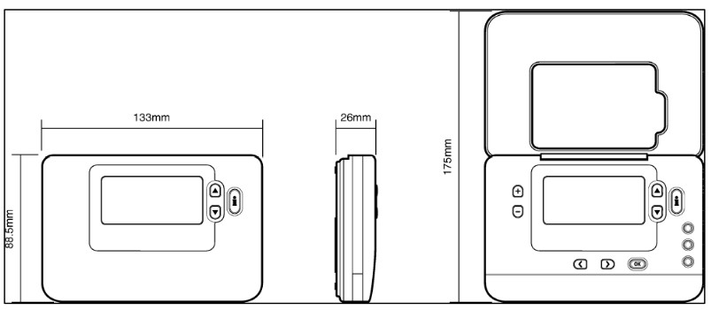
| Dimensions | 133 x 88.5 x 26 mm (w x h x d)130 x 175 x 26 mm (w x h x d)flap open) |
| Environmental | Operating temperature range 0 to 40 o C Shipping and storage temperature range -20 to 55 o CHumidity range 10 to 90% rh, noncondensing |
| Approvals | Designed to meet European ENapprovals EN60730-1(Nov 2000),EN55014-1 (1997), EN55014-2 (2000) |
INSTALLER SET-UP
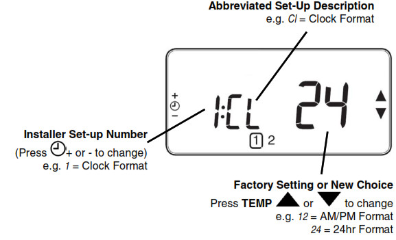
To enter the installer set-up mode:a) Press the OFF button.b) Press and hold the INFO i button and the two program buttons ‘< >’ together.c) The unit will display the first parameter of installer parameter group category 1 (from n.1 to n.19).d) Press the TEMP ![]() or
or ![]() buttons to change the factory setting. The display will flash indicating that a change has been made.e) Press the green OK button to confirm this change and the display will stop flashing.f) Press the + button to go to the next parameter.g) Press the program button > to go to category 2 in the Installer mode (from n.1 to n.5).h) To exit the installer mode, press the AUTO, MAN or OFF buttons.
buttons to change the factory setting. The display will flash indicating that a change has been made.e) Press the green OK button to confirm this change and the display will stop flashing.f) Press the + button to go to the next parameter.g) Press the program button > to go to category 2 in the Installer mode (from n.1 to n.5).h) To exit the installer mode, press the AUTO, MAN or OFF buttons.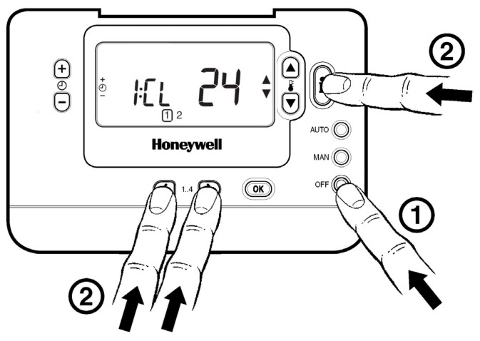
In Installer set-up we can:
- Set-up specific applications
- Enable special features
| Specific Applications | Setting | What do you need to change? | ||
| Cycle/ Hour | Minimum ON time(in minutes) | Note :a.To change Cycle/Hour, please go to parameter n. 2, category 2 in the installer set-up mode.b.To change Minimum ON Time, please go to parameter n. 1, category 2 in the installer set-up mode. | ||
| Heating | Gas Boilers (<30KW) | 6 | 1 | No action required |
| Oil Boiler | 3 | 4 | 1.Set Minimum ON Time to 4 minutes.2.Set Cycle/Hour to 3. | |
| Thermal Actuator | 12 | 1 | Set Cycle/Hour to 12. | |
| Zone valve | 6 | 1 | No action is required. | |
| Electric heating (for applications <5A) | 12 | 1 | 1. Set Cycle/Hour to 12. |
| Special Features | Description | What to do if we wish this feature |
| AM-PM/ 24hr Display | Change display format (default 24hr). | Set parameter n.1, category 1 in the installer set-up mode to 12. |
| Pump exercise | When enabled the Pump Exercise will switch the relay on for 1 minute at 12:00 if the relay has not been switched on since 12:00 the previous day.While in Holiday mode the Pump Exercise feature, if enabled, will operate. | Set parameter n.5, category 2 in the installer set-up mode to 1. |
| Upper-Temperature Limit | The normal upper-temperature limit of 35°C can be reduced down to 21 °C to save the homeowner energy. Useful if the homeowner rents to tenants. | Set parameter n.6, category 1 in the installer set-up mode to the desired limit. |
| Lower Temperature Limit | The normal lower temperature limit of 5°C can be increased up to 21 °C to protect the inhabitants from cold. Useful if the inhabitants include the elderly, children or disabled. | Set parameter n.7, category 1 in the installer set-up mode to the desired limit. |
| Temperature Offset | If the thermostat is located in a hot/cold location and cannot be moved because of wiring then the measured/ displayed temperature can be adjusted by +/- 3°C. Useful if the homeowner wants the reading to match another appliance temperature display. | Set parameter n.12, category 1 in the installer set-up mode to the desired offset value. |
| Proportional Band Width | Can be adjusted up to 3°C (default is 1.5 °C) to provide better temperature control (less overshoot).Useful for:a.Well insulated homes with oversized heating systems.b.Air systems with fast response. | Set parameter n.13, category 1 in the installer set-up mode to the desired value. |
| Parameter | Installer Set-Up Number / Abbreviation (Press + or – keys to select) | Factory Setting | Optional Setting | Installer Set-Up Category(Press PROG keys i< or >’ to select) | ||
| Display | Description | Display/Setting | Description | |||
| Category 1: Thermostat Parameters | ||||||
| AM-PM / 24hr Display | 1:C1 | 24 | 24 hr clock display | 12 | 12 hrAM / PMdcckcisplay | 1 |
| RESET Time / Temperature Program | 2:rP | 1 | Time / Temperature profile set to factory defaultChanges to 0 when one of the time/temp profiles are changed | 01 | Time / Temperature is as programmedTo restore the factory profile set to 1 | 1 |
| Upper-Temperature Limit | 6:uL | 35 | 35°C Upper Temp. Limit | 21 to 34 | 21°C to 34°C adjustments in 1°C steps | 1 |
| Lower Temperature Limit | 7:LL | 5 | 5°C Lower Temp. Limit | 6 to 21 | 6°C to 21°C adjustments in 1°C steps | 1 |
| Temperature Offset | 1210 | 0 | No offset | -3 to +3 | -3°C to 4-3°C adjustment in 0.1°C steps | 1 |
| Proportional Eland Width | 13:Pb | 2. | 1.5°C Proportional Band | 1.6 to 3.0 | 1.6°C to 3.0tadjustment in 0.1°C steps | 1 |
| Reset Parameters to FactoryDefaults | 19:FS | 1 | All settings held are the factory defaults. Changes to 0 when one of theparameter values are changed | 01 | Settings are as modified aboveTo restore the factory profile set to 1 | 1 |
| ‘Category 2: System Parameters (You must press the 5.’ program key to enter this section) | ||||||
| Minimum ON Time | 1:01 | 1 | 1 minute minimum ON time | 2 to 5 | 2 – 2 minutes3 – 3 minutes4 – 4 minutes5 – 5 minutes | 2 |
| Cycle Rate | 2:Cr | 6 | 6 cycles per hour (mph) for gas boilers. zone valves and fan-coil | 3/9/12 | 3 – 3 cph9 – 9cph12 – 12 cph | 2 |
| Pump Exercise | 5:PE | 0 | Pump Exercise Disabled | 1 | Pump Exercise Enabled | 2 |
DIMENSIONS
INSTALLATION
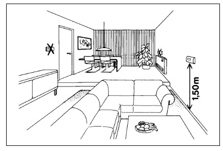
LOCATIONThe CM701 thermostat is the control element of the heating system and, therefore, MUST be located in a position with good air circulation, at average room temperature, and on an inside wall, 1.5 meters above the floor level. Do not position the CM701 thermostat near sources of heat (radiators, hot-air vents, TV or lights), near doors or windows, or indirect sunlight.MOUNTINGThe CM701 thermostat can be mounted directly on the wall surface or onto an electrical wall box.WIRING The CM701 thermostat is designed for fixed wiring only and must be installed in accordance with the latest l.E.E. regulations. Ensure the wiring connection to the supply is via a fuse rated at no more than 5 amps and a Class “A” switch (having a contact separation of at least 3 mm in all poles).
IMPORTANT
- The installer must be a trained service engineer
- Disconnect the power supply before beginning installation
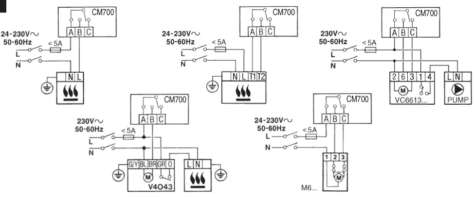
WIRING
ORDERING SPECIFICATION
| Description | Model | Logo | Literature | Spec Sheet |
| 1-day programmable thermostat | CMT701A1006 | Honeywell | French, Dutch, Italian, Spanish, German, Portuguese. | ENOH8543 |
![]()
Honeywell Control Systems LimitedNewhouse Industrial EstateMotherwell ML1 5SBUnited Kingdom
http://europe.hbc.honeywell.comEN0H 8543 UK07 R08/05
[xyz-ips snippet=”download-snippet”]