Honeywell Current Switches Solid and Split Core Instruction Manual
APPLICATION
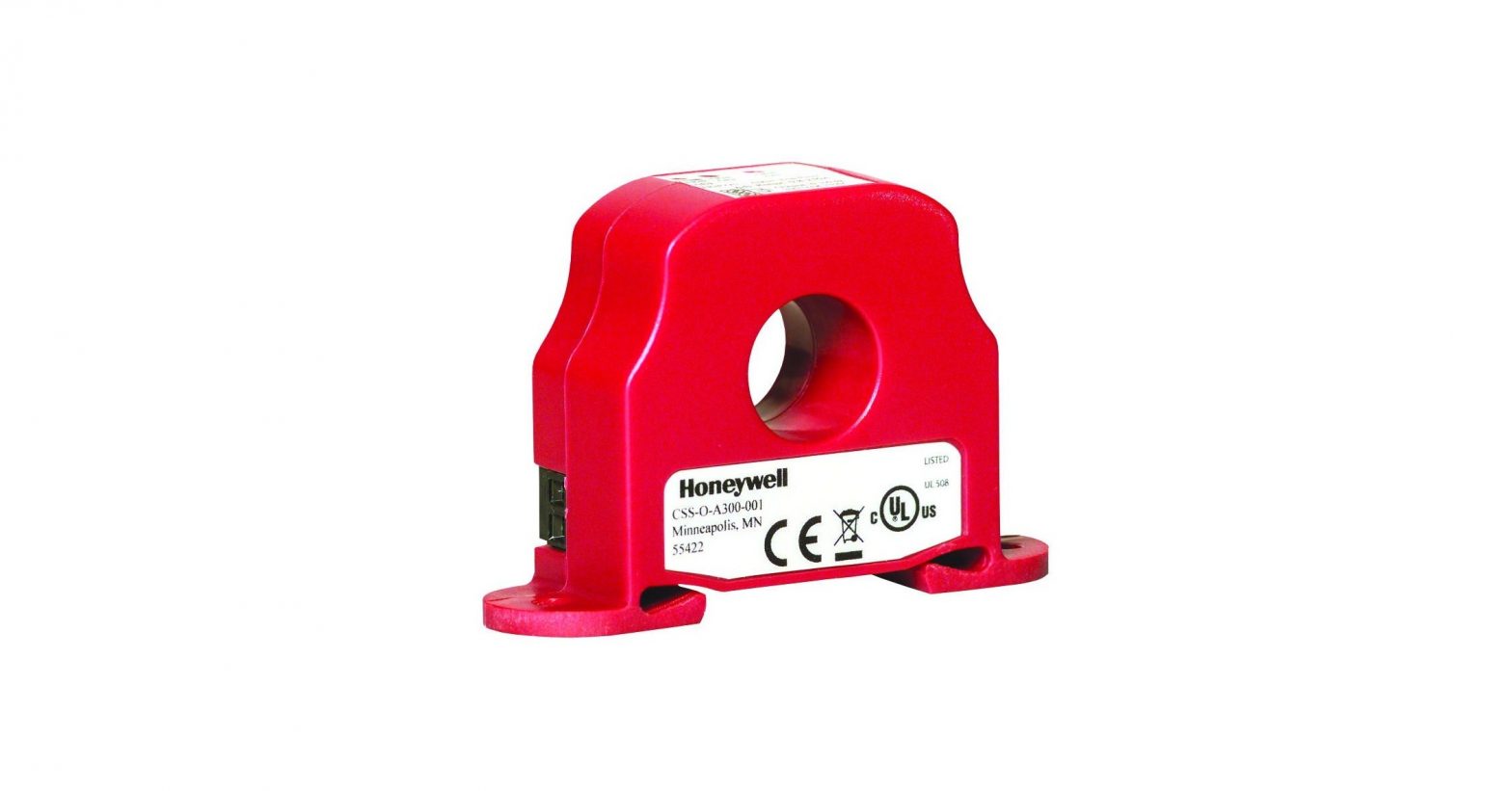
The CS- and CP- current switches are designed for use in any AC current monitoring application in which you are looking to monitor a particular piece of equipment.
SPECIFICATIONS
- Monitored Current Type: AC Current
- Maximum AC Voltage: 600 VAC
- Isolation Voltage: 2200 VAC
- Supply Voltage:
- +8.5 to 30 VDC (Reverse Polarity Protected)
- 250 Ohm Load (1-5 VDC): +13.5 to 30 VDC
- 500 Ohm Load (2-10 VDC): +18.5 to 30 VDC
- Operating Temperature Range: 5 to 104ºF (-15 to 40ºC)
- Operating Humidity Range: 0 to 95%, non-condensing
- Wire Recommendations: 2 Conductor (Shielded Cable)
- Wire Size:
- 18 to 24 AWG (0.823 mm2 to 0.205 mm) Copper Wires only
- Terminal Block Torque Rating: 4.43 to 5.31 in-lbs. (0.5 to 0.6 Nm)
- Minimum Mounting Distance:
- 1” (2.6 cm) between current sensor & other magnetic devices (Relays, Contactors, Transformers)
- Agency Approvals: CE (-RMS Versions): CE to IEC 61326-1: 2012 Class A, UL/CUL US Listed (UL 508) Ind. Control Equipment (File # E309723), RoHS2, WEEE
PLEASE READ INSTRUCTIONS CAREFULLY BEFORE INSTALLATION!
![]() WARNING: This product is not intended to be used for Life or Safety applications. This product is not intended for use in any hazardous or classified locations. The Current Switches must be used on Insulated Conductors Only!
WARNING: This product is not intended to be used for Life or Safety applications. This product is not intended for use in any hazardous or classified locations. The Current Switches must be used on Insulated Conductors Only!
![]() WARNING: Electrical Shock Hazard Disconnect and lock out all power sources before installation as severe injury or death may result from electrical shock due to contact with high voltage wires. Never rely on the LEDs to determine whether power is present at the current switch. At very low monitored input currents the LEDs may not light.
WARNING: Electrical Shock Hazard Disconnect and lock out all power sources before installation as severe injury or death may result from electrical shock due to contact with high voltage wires. Never rely on the LEDs to determine whether power is present at the current switch. At very low monitored input currents the LEDs may not light.
INSTALLATION
Make sure that all installations are in compliance with all national and local electrical codes. Only qualified individuals that are familiar with codes, standards, and proper safety procedures for high-voltage installations should attempt installation. The current switches will not require external power, since the power for the current switch is induced from the conductor being monitored.The current switch may be mounted in any position using the two #8 x 3/4” Tek screws and the mounting holes in the base, or snapped directly on to the 35mm DIN rail (See Fig. 1). Leave a minimum distance of 1” (3 cm) between the current switch and any other magnetic devices such as contactors and transformers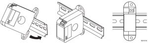 Fig. 1. Sensor Placed On Rail.
Latch Operation for Split Core Models
Press down on the side tab and swing the top of the unit up to open the split core current switch as shown in Fig. 2. Press down firmly on the cover to close the current switch. An audible “click” will be heard as the tab slides over the tongue on the base.
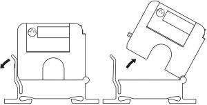 Fig. 2. Opening Split Core Models.
![]() CAUTION: Mating surfaces of the magnetic core are exposed when the sensor is open. Electrical contact grease, present on the cores to prevent corrosion, can capture grit and dirt if care is not exercised. Operation can be impaired if anything prevents good contact between pole pieces. Visually check the mating parts of the core before closing the current sensor.
CAUTION: Mating surfaces of the magnetic core are exposed when the sensor is open. Electrical contact grease, present on the cores to prevent corrosion, can capture grit and dirt if care is not exercised. Operation can be impaired if anything prevents good contact between pole pieces. Visually check the mating parts of the core before closing the current sensor.
LEDs
Fixed Trip Point Models
The Red LED will indicate whether the current is above (LED On) or below (LED Off) the fixed trip point. At very low monitored input currents the Red LED may not light to indicate the current is above the trip point.
Adjustable Trip Point Models
The Red LED will indicate whether the current is above the adjustable trip point. The Blue LED will indicate whether the current is below the adjustable trip point. At very low monitored input currents the LEDs may not light.
Application Notes
the sensor multiple times. The loops increase the current measured by the current switch. Each time the conductor passes through the current switch window equals one loop. (See Fig. 3). To determine the proper number of loop required, take the rated Fixed Trip Point or Minimum Adjustable Trip Point (see Table 2) of the current switch and divide it by the Operating Current of the Monitored Device, add one (1), then round up to the nearest whole number. Example: When using the CS-O-A, a small fan operating at 0.17A should be wrapped through the sensor four times to give you a total operating current of 0.68 Amps flowing through the CS-O-A. Formula Example: (0.5A/0.17A) = 2.94 + 1 = 3.94, which rounded up equals 4 loops.
WIRING

We recommend the use of a two conductor 16 to 22 AWG shielded cable or twisted pair copper wire only, for all current switch applications. A maximum wire length of less than 30 meters (98.4 feet) should be used between the current switch and the Building Management System or controller.
NOTE: When using a shielded cable, be sure to connect only (1) end of the shield to ground at the controller. Connecting both ends of the shield to ground may cause a ground loop.
When removing the shield from the sensor end, make sure to properly trim the shield to prevent any chance of shorting. The current switch output terminals represent a solid-state switch for controlling both AC and DC loads and are not polarity sensitive. Tighten the screws at the terminal block connections to the recommended torque of 0.5 to 0.6 Nm (4.43 to 5.31 in-lbs.). The aperture (hole) size of the current switch is 0.75” (1.90 cm).
Application Examples
See Fig. 4 and Fig. 5 for two different current switch applications using your Building Management Syste (DDC/PLC Controller). Fig. 4 is showing the use of the Current Switch as a Digital Input to your DDC Controller, whereas Fig. 5 is showing you how to use the Current Switch in conjunction with your building management system to monitor belt loss on a motor.
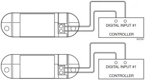 Fig. 4. Digital Circuit
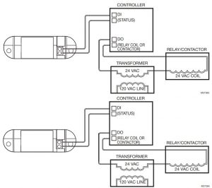 Fig. 5. Analog Circuit
Calibration of Adjustable Trip Point (Adjustable switches only)
The adjustable current switch has an operating range of 0-250 Amps, Do not exceed! The current switch has an adjustable trip point range of 0.50 – 220 Amps, 1.50 – 220 Amps, or 0.60 – 180 Amps depending on the model. See Figure 6 to determine the adjustable trip point range per model number. The adjustable current switch comes with its fifteen-turn adjustment potentiometer set counter. clockwise to the maximum trip point position. The adjustable current switch can monitor Under-load, Normal Load, and Overload conditions, depending on how it’s set.
NORMAL LOADS:
The procedure below is for the Normal load condition for part numbers CS-O-A, CP-O-A and CP-O-AL. With power on, turn the 15-turn adjustment potentiometer counterclockwise until the Red LED turns on and stop immediately. The adjustable current switch is now tripped. The adjustable current switch Hysteresis (Dead Band) is 10% of the trip point typically.
TROUBLESHOOTING
| Problem | Solution |
| LED is on but the current switch didn’t activate | Disconnect the wires from the current switch output. Measure the resistance across the contacts with an Ohmmeter. See Table 2 for the actual resistance readings for an open or closed switch reading. |
| LED didn’t turn on and the current switch didn’t activate | Verify that the current flowing in the conductor being monitored is above the fixed trip point as listed in the operating specifications. If the sensor is monitoring less than the fixed trip point See Fig. 3. |
| Red LED didn’t turn on and the current switch didn’t activate | Verify that the conductor you are monitoring is above the adjustable trip point. If the sensor is monitoring less than the adjustable trip point, see Fig. 3. |
| LED not on but the Current Switch is Activated | LED not indicating correctly, may have been damaged |
| Sensor doesn’t switch at all, regardless of current level. | Adjustment potentiometer is probably set to its maximum or minimum position. Turn the Pot clockwise all the way and verify if the LED switches from Blue to Red. |
| Current Switch is operating at a low-level current or failing to operate within the accuracy specifications. | For CP-O-F Series, visually check the mating parts of the core to ensure there is no debris between the split contacts. Remove all debris or dust manually and close the current sensor, See Fig. 2. Retest the sensor in your application. |
CURRENT SWITCHES – SOLID AND SPLIT CORE
Table 2.
| Model # | Adjustable Trip Point | Fixed Trip Point | Resistance if switch open | Resistance if switch closed |
| CS-O-A | 0.5 – 220 Amps | N/A | Greater than 1 Meg ohms | Less than 10 ohms |
| CP-O-A | 1.5 – 220 Amps | N/A | ||
| CP-O-AL | 0.6 – 180 Amps | N/A | ||
| CP-C-A | 1.5 – 220 Amps | N/A | ||
| CS-O-F | N/A | 0.25 Amps | ||
| CS-C-F | N/A | 0.25 Amps | ||
| CP-O-F | N/A | 1.5 Amps | ||
| CP-O-FL | N/A | 0.5 Amps | ||
| CP-C-F | N/A | 1.5 Amps |
WEEE Directive
At the end of their useful life the packaging and product should be disposed of via a suitable recycling center. Do not dispose of with household waste. Do not burn.
REGULATORY INFORMATION
FCC REGULATIONS: § 15.19 (A)(3)
This device complies with part 15 of the FCC Rules. Operation is subject to the following two conditions:
- This device may not cause harmful interference, and
- This device must accept any interference received, including interference that may cause undesired operation.
IC REGULATIONS: RSS-GEN
This device complies with Industry Canada’s licenseexempt RSSs.
Operation is subject to the following two conditions:
- This device may not cause interference; and
- This device must accept any interference, including interference that may cause undesired operation of the device.
FCC WARNING (PART 15.21) (USA ONLY)
Changes or modifications not expressly approved by the party responsible for compliance could void the user’s authority to operate the equipment.
CHINA ROHS COMPLIANCE INFORMATION ENVIRONMENT-FRIENDLY USE PERIOD (EFUP) TABLE
| Component Name | ||||||
| Lead (Pb) | Mercury HG | Cadmium (Cd) | Chromium VI Compounds (Cr6+) | Polybrominated Biphenyls (PBB) | Polybrominated Diphenyl Ethers (PBDE) | |
| Assorted capacitors | O | O | O | O | O | O |
| Assorted resistors | O | O | O | O | O | O |
| Core | O | O | O | O | O | O |
| Screw | O | O | O | O | O | O |
By using this Honeywell literature, you agree that Honeywell will have no liability for any damages arising out of your use or modification to, the literature. You will defend and indemnify Honeywell, its affiliates and subsidiaries, from and against any liability, cost, or damages, including attorneys’ fees, arising out of, or resulting from, any modification to the literature by you.
Home and Building TechnologiesIn the U.S.:Honeywell 715 Peachtree Street NE Atlanta, GA 30308customer.honeywell.com

[xyz-ips snippet=”download-snippet”]