![]()
INSTALLATION INSTRUCTIONS FOR THEMICRO SWITCH CX SERIES,WEATHER SEALED, EXPLOSION-PROOFLIMIT SWITCHES

![]() WARNINGIF USED IN APPLICATIONS CONCERNING HUMAN SAFETY
WARNINGIF USED IN APPLICATIONS CONCERNING HUMAN SAFETY
- Only use NC direct opening (“positive opening”/”positive break”) contacts, identified by the symbol .
- Do NOT use flexible/adjustable actuators. Only use actuators designed for safety applications.
- Do NOT defeat, tamper, remove, or bypass this switch.
- Hazardous voltage, disconnect power before servicing.
- Strictly adhere to all installation and maintenance instructions.
- Consult with local safety agencies and their requirements when designing a machine-control link, interface and all control elements that affect safety.
Failure to comply with these instructions could result in death or serious injury
GENERAL INFORMATION
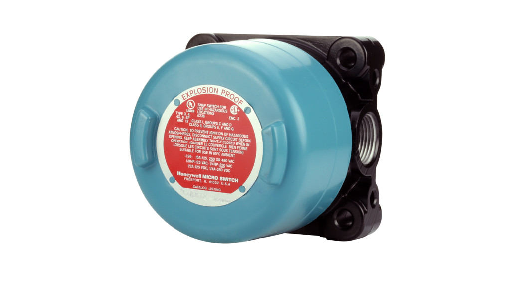
Sealed construction for Honeywell CX explosion-proof switches provides protection from the entry of water, dust and oil as defined in NEMA 3, 4, 4X, 6, 6P, 13, and IP66/IP67 as defined in IEC 529.CX Series products with conduit types ¾-14NPT also meet the North American Hazardous Locations Designation: Class I, Group C and D; Class II, Groups E, F, and G. CX listings beginning with numbers 14, 16, 24, 26, or 84 (example: 14CX1) also meet Class I, Group B. These explosion-proof and weather-sealed switches are protected from flammable hydrocarbon atmospheres, metal dust, coal dust, and grain dust, and comply with UL Standard: UL 894 and UL 1203, CSA Standard: C22.2no. 25-1966, C22.2 no. 30-M1986.Select CX Series products also meet the European Hazardous Locations Designation: Categories II 2 G Ex d IIC T6 and II 2 D tD A21, KEMA 01ATEX2111X and complies with the European Directive on Equipment and Protective Systems Intended for Use in Potentially Explosive Atmospheres (2014/34/ EU) commonly referred to as the ATEX Directive. Compliance with the Essential Health and Safety Requirements has been assured by compliance with EN 60079-0:2006, EN 60079-1:2004, EN61241-0: 2006, and EN61241-1: 2004. The European-approved products have a temperature range of -40 °C to 70 °C [-40 °F to 158 °F], andwhen used within the maximum voltage and current specified on the product will have no heating problems.
CX Series products also meet the Brazilian hazardous Locations Designation:Ex d IIC T6 GbEx tb IIIC T85 °C DbIP 66/67and comply with INMETRO requirements.Compliance with Essential Health and Safety Requirements has been assured by compliance withABNT NBR IEC 60079-0:2008ABNT NBR IEC 60079-1:2009ABNT NBR IEC 60079-31:2011ABNT NBR IEC 60529:2009Please refer to certificate number TÜV 14.0553 for conditions of safe use.Notice: For ambient temperatures above 60 °C [140 °F], cables and cable glands suitable for a temperature of at least 80 °C [176 °F] shall be used. For use in potentially explosive atmospheres caused by the presence of flammable gases, fluids or vapors. The cable entry devices and the closing elements of unused apertures shall be of a certified flameproof type, suitable for the conditions of use and correctly installed.For use in potentially explosive atmospheres caused by the presence of combustible dust. The cable entry devices and the closing elements of unused apertures shall be of a certified flameproof type, suitable for the conditions of use and correctly installed. The minimum ingress protection requirement of IP6X according to EN 60529 must be satisfied. Refer to the Certificate IECEx TSA 06.0003X for conditions of safe use.Application Note: Enclosures are based, in general, on the broad definitions outlined in NEMA standards. Therefore, it will be necessary for the user to determine that a particular enclosure is adequate when exposed to the specific conditions that might exist in intended applications. Except as might otherwise be noted, all references to products relative to NEMA enclosure types are based on MICRO SWITCH evaluation only.IMPORTANT: Switches without shaft re-storing force do not have overtravel stops. On switches with potentiometers, use care to insure that overtravel does not exceed 125° in the application and during set-up.
MICROSWITCH HAZARDOUS LOCATION SWITCH, CX SERIES
LEVER POSITIONINGLoosen the screw with a 9/64 inch hexagon key wrench, move the lever to the desired position and securely tighten the screw until the “teller tab” can no longer be moved by hand. Then tighten the screw another 1/8 to 1/4 turn to assure that the lever is tight on the shaft. Hexagon key wrenches are provided in adjusting toolset LSZ4005 for this purpose.
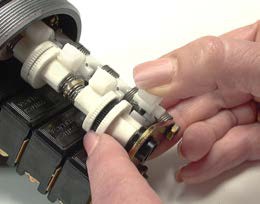
CAM ADJUSTMENTPretravel, overtravel, and actuation sequencing can be adjusted and/or modified in the field. No tools are required.
To Adjust Rotary Types:
- Lift cam follower.
- Move cam wheel axially to disengage teeth on the wheel from teeth on shaft disc.
- Turn the cam wheel to the desired position. Turning in direction of shaft rotation advances operate point. Pretravel decreases and overtravel thereby increases. Each notch on the cam wheel represents an operating point change of 7°20’. The symbols on the cam wheel simplify changing rotation from clockwise to counterclockwise to center neutral, or vise versa. If the switch operates on clockwise and counterclockwise rotation, the pointer on the cam follower lines up with the symbol
 or symbol on the cam wheel. When symbol lines up, pretravel of 15° max. is obtained. When the symbol lines up, 80° max., pretravel is obtained. Operation is in the direction of the inclined surface of the symbol when or lines up with the pointer on the cam follower.
 - When cam wheel has been rotated to the desired location, release cam wheel to engage with mating shaft disc.
- Release cam follower.
CX Wiring MethodsHoneywell recommends that conduit be installed per NEC articles 501-4 and 501-5.
REPLACEMENT PARTSReplacement switch assemblies consist of the components subject to mechanical or electrical wear. They include basic switches, cam wheels, cam followers, and springs. The assemblies are factory adjusted to have the same operating characteristics as new complete switches.How to OrderCatalog listings for complete switches can be converted to replacement switch assembly catalog listings as follows:Momentary action rotary or plunger actuated switches with shaft or plunger restoring force: To order a replacement assembly, change the first digit in the catalog listing for a complete switch to 9 for rotary switches or to 10 for plunger switches.For example, the replacement switch assembly for a 12CX5 rotary switch = 92CX5.Maintained action rotary switches without shaft restoring force: To order a replacement assembly, change the first digit to a 9 and drop the first digit following the letters CX.Example: 12CX12=92CX2
| Rotary SwitchAssembly | 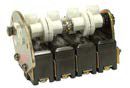 |
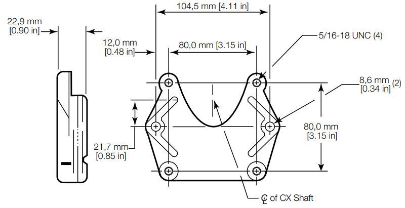
REPLACEMENT LEVERSTo order replacement levers, order the part number which is metal stamped on either the lever or the hub. Only nonsparking levers can be used to retain the explosion-proof properties.MOUNTING ADAPTER —15PA148-CXAvailable for adapting CX to existing 2 hole mount.
ACTUATION SPECIFICATIONS
| Catalog ListingPrefix | 11CX, 21CX,61CX, 71CX,81CX, 91CX* | 12CX, 22CX,62CX, 72CX,82CX, 92CX* | 14CX, 24CX,64CX, 74CX,84CX, 94CX* | 16CX, 26CX,66CX, 76CX,86CX, 96CX* | 1172CX, 2172CX,9172CX* |
| Pretravel, max. | 15° | 15° | 30° | 30° | 15° |
| Differential travel max. | 5° | 10° | 25° | 20° | 5° |
| Overtravel, min. | 90° | 90° | 75° | 75° | 90° |
| Circuitry | Single-PoleDouble-Throw | Single-PoleDouble-Throw | Double-PoleDouble-Throw | Single-PoleDouble-Throw | (Gold Contact) Single-PoleDoubleThrow |
| Electrical ratings | UL/CSA Rating:L96 15 A, 120, 240, or480 Vac½ Hp, 120 Vac;¼ Hp, 240 Vac0.5 A, 125 Vdc,0.25 A, 250 Vdc | UL/CSA Rating:L23 20 A, 120, 240, or480 Vac1 Hp, 120 Vac;2 Hp, 240 Vac0.5 A, 125 Vdc,0.25 A, 250 Vdc | UL/CSA Rating:L5910 A, 120 or 240Vac0.3 A, 125 Vdc,0.15 A, 250 Vdc | UL/CSA Rating:L221 A, 125 Vac | UL/CSA Rating:L221 A, 125 Vac |
*listing indicates replacement parts
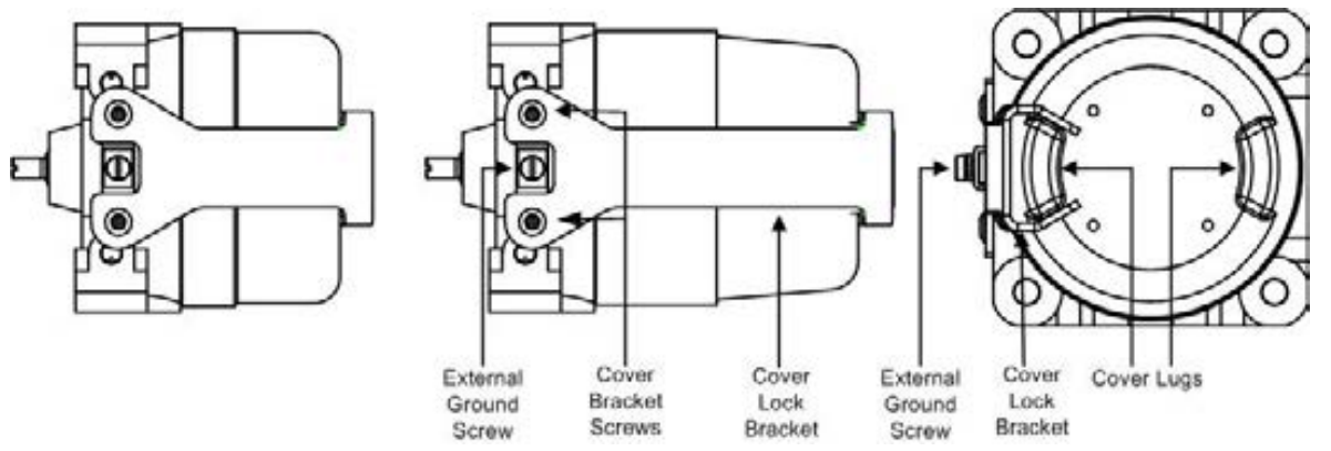
ASSEMBLE COVER LOCK BRACKET FOR EUROPEAN COMPLIANCE
- Make sure the switch cover is tightened so a lug aligns with the external ground screw.
- Remove bracket screws and special screwdriver bit from the bag included in the box.
- Fit top of bracket around lug on the cover.
- Fit external ground screw into a notch in the bottom of the bracket.Screw holes in the bottom of the bracket should align with screw holes in the housing on either side of the external ground screw.
- Use included screwdriver bit to tighten screws into the holes.
WARRANTY/REMEDYHoneywell warrants goods of its manufacture as being free of defective materials and faulty workmanship. Honeywell’s standard product warranty applies unless agreed to otherwise by Honeywell in writing; please refer to your order acknowledgment or consult your local sales office for specific warranty details. If warranted goods are returned to Honeywell during the period of coverage, Honeywell will repair or replace, at its option, without charge those items it finds defective.The foregoing is buyer’s sole remedy and is in lieu of all other warranties, expressed or implied, including those of merchantability and fitness for a particular purpose. In no event shall Honeywell be liable for consequential, special, or indirect damages.While we provide application assistance personally, through our literature and the Honeywell website, it is up to the customer to determine the suitability of the product in the application.Specifications may change without notice. The information we supply is believed to be accurate and reliable as of this printing. However, we assume no responsibility for its use.
For more informationHoneywell Safety and Productivity Solutions service its customers through a worldwide network of sales offices and distributors. For application assistance, current specifications, pricing, or the nearest Authorized Distributor, visit our website or call:USA/Canada +1 302 613 4491Latin America +1 305 805 8188Europe +44 1344 238258Japan +81 (0) 3-6730-7152Singapore +65 6355 2828Greater China +86 4006396841
![]()
HoneywellSafety and Productivity Solutions830 East Arapaho RoadRichardson, TX 75081sps.honeywell.com/ast
PK 88136-14-ML | 14 | 05/21© 2021 Honeywell International Inc. All rights reserved.
References
[xyz-ips snippet=”download-snippet”]