
Honeywell EM3S-V-P-D E-Mon Class 6200 Pulse Meter

Models:
- EM3S-V-P-D
- EM3S-V-P-J
- EM3S-V-P-R
- EM3S-V-P-ER
WARNING
PRE-INSTALLATION INFORMATIONThe E-Mon® Class 6200 meter is a 3-phases meter used to monitor electric power usage of individual loads after the utility meter. Carefully read these operating instructions completely through before mounting and commissioning. For your own safety and for operational reliability, comply with all warnings and instructions. The provided protection can be impaired if the unit is not used in accordance with these operating instructions.
WARNINGUse of this instrument, Class 6200, in a manner inconsistent with this manual or not specified by the manufacturer in writing, can cause permanent damage to the unit and/or serious injury to the operator. The protection and safety features provided by this equipment may become impaired or otherwise compromised. High voltages present on main terminal block screw terminals. Risk of serious injury and/or electrical shock exists. Prior to performing any wiring operations, review all contents of the user manual and de-energize the MAINS power switch. Only qualified personnel should perform installation wiring. Installation wiring must comply with all local and national electrical codes.
WARNINGPlease read markings printed on meter side. Carefully read these instructions and “Quick Starting Guide” (included in the package) completely thoroughly before installation.
PRODUCT OVERVIEW
| Description | Function | |
| 1 | Seal lock | Seal lock |
| 2 | Current Sensor Terminals | Inputs for current measurement |
| 3 | Up/Down Buttons | Use to navigate «up/down» or «left/right» |
| 4 | Set/Back Button | Short press = confirm; Long press = back |
| 5 | Setup lock | Setup lock |
| 6 | I/O Terminal | Push-in connector for I/O or Pulse meter |
| 7 | Voltage Terminals | Inputs for Voltage measurement |
| 8 | Manufacturer Specific ID | Manufacturer Specific ID |
| 9 | LCD-Display | User interface |
| 10 | Metrology LED | 1000 imp/kWh (infrared) |
| 11 | Status LED | Shows the meter status |
INSTALLATION
Single-Phase Three-Wire schematic
DANGER HIGH VOLTAGE! Voltage rating: 100/200 … 230/460 VAC
- S1: Positive connection (White wire of current sensor)
- S2: Negative connection (Black wire of current sensor)
Three-Phase Three-Wire Delta schematic
DANGER HIGH VOLTAGE! Voltage rating: 100 … 277 VAC
- S1: Positive connection (White wire of current sensor)
- S2: Negative connection (Black wire of current sensor)
Three-Phase Four-Wire Wye schematic
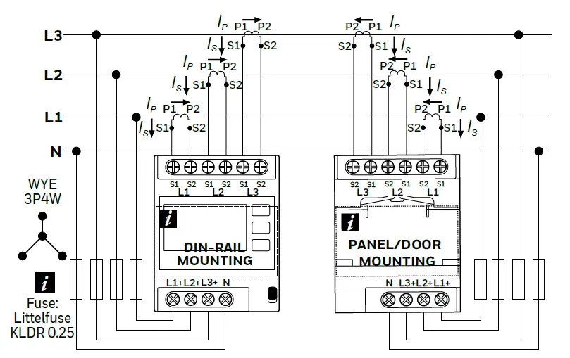
DANGER HIGH VOLTAGE! Voltage rating: 57.7/100 … 277/480 VAC
- S1: Positive connection (White wire of current sensor)
- S2: Negative connection (Black wire of current sensor)
DIMENSIONS
DISPLAY
ENERGY
- Total Registers
- Active Energy
- Import (+A)
- Export (-A)
- Demand
- Active (+A)
- Import (+A)
- Export (-A)
- Maximum Demand
- Active Energy
- Import (+A)
- Export (-A)
- Partial
- Import (+A)
- Export (-A)
- Sum (+AP)+(-AP)
- Difference (+AP)-(-AP)
MONITOR
- Instant
- Line-Neutral Voltage (-N U)
- Line-Line Voltage (-1,2,3 U)
- Current (I)
- Active Power (+A)
- Active Power (-A)
- Reactive Power (+R)
- Reactive Power (-R)
- Apparent Power (+S)
- Apparent Power (-S)
- Frequency (F)
- Power Factor
- Min (Minimum)
- Line-Neutral Voltage
- Line-Line Voltage
- Current (I)
- Active Power (|+A|+|-A|)
- Active Net Power (|+A|-|-A|)
- Average
- Line-Neutral Voltage
- Line-Line Voltage
- Current (I)
- Active Power (|+A|+|-A|)
- Active Net Power (|+A|-|-A|)
- Max (Maximum)
- Line-Neutral Voltage
- Line-Line Voltage
- Current (I)
- Active Power (|+A|+|-A|)
- Active Net Power (|+A|-|-A|)
SETUP
- Reset Registers
- Reset Partial Reg.
- Reset Min/Max/Avg.
- Reset PEAK
- System (Wiring)
- 3P4W
- P1-P3+N
- P2-P3+N
- P1-P2+N
- 3P3W
- P1+N
- P2+N
- P3+N
- Frequency
- 50 Hz
- 60 Hz
- Supply*
- 277/480
- 240/415
- 230/400
- 220/380
- 127/220
- 120/208
- Wiring Check**
- Acknowledge
- Phase direction
- System
- In / Out
- CS Ratio Primary
- Set Value
- CS Ratio Secondary
- Set Value
- Display
- Backlight (On/Off)
- Clock
- Time/Date
- Info
- Port 1Pulse Ratio (mS)Pulse Duration (mS)React to
- Port 2
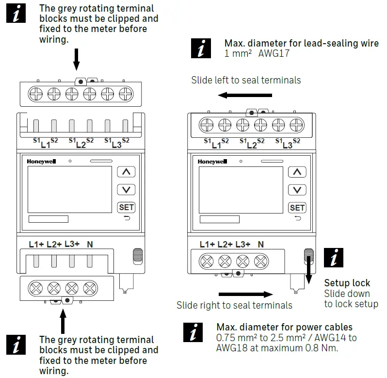
SEALING
CERTIFICATION
Declaration of conformityDownload the Declaration of conformity by scanning the QR codes with a QR code reader on your mobile device or click on link https://hwll.co/dyut5.FCC NoticesContains FCC ID: SQGBL654
The enclosed device complies with Part 15 of the FCC Rules. Operation is subject to the following two conditions:
- This device may not cause harmful interference, and
- This device must accept any interference received, including interference that may cause undesired operation.
This equipment has been tested and found to comply with the limits for a Class B digital device, pursuant to Part 15 of the FCC Rules.These limits are designed to provide reasonable protection against harmful interference in a residential installation. This equipment generates, uses and can radiate radio frequency energy and, if not installed and used in accordance with the instructions, may cause harmful interference to radio communications. However, there is no guarantee that interference will not occur in a particular installation. If this equipment does cause harmful interference to radio or television reception, which can be determined by turning the equipment off and on, the user is encouraged to try to correct the interference by one of the following measures:
- Reorient or relocate the receiving antenna.
- Increase the separation between the equipment and receiver.
- Connect the equipment into an outlet on a circuit different from that to which the receiver is connected.
- Consult the dealer or an experienced radio/TV technician for help.
FCC Caution: Any changes or modifications not expressly approved by the party responsible for compliance could void the user’s authority to operate this equipment.
 report this ad
*System voltage options will be vary as per set System (Wiring) selection.**Different types of errors as per instance will be visible under this option.
References
[xyz-ips snippet=”download-snippet”]