Honeywell FP5000 Pressure Transducer User Guide
DESCRIPTION
The Honeywell Model FP5000 Series is a media-isolated piezoresistive silicon pressure sensor offering multiple output options for reading pressure over the specified full-scale pressure span and temperature range.It is compensated for sensor offset, sensitivity, temperature effects and non-linearity to offer improved thermal stability and accuracy. Hastelloy® C276 and 316L stainless steel wetted parts provide durability with abrasive or corrosive media.
DIFFERENTIATION
- Offers improved accuracy and reliability
- Configurable platform enables a sensor to be built to customer requirements. Simplified nomenclature and order codes make ordering easier
- Many pressure and operating temperature range options
- Built from stocked components; most configurations are shipped within ten business days
- Extensive history of pressure measurement know-how
- Bi-directional differential output available
FEATURES
- Pressure ranges from 10 in-H2O [0.36 psi] up to 5000 psi
- Gage, absolute, vacuum, barometric, compound, and differential wet/wet pressure types Higher accuracy to 0.1 %FSS BFSL
- Multiple output types: 0 Vdc to 5 Vdc, 0 Vdc to 10 Vdc, 4 mA to 20 mA, 5 Vdc ±5 Vdc, 12 mA ±8 mA
- Multiple electrical and pressure connection options
- Zero adjustment through potentiometer
- Operating temperature ranges from -40°C to 125°C [-40°F to 250°F]
- Multiple compensation temperature ranges
- Faster response and higher resolution
- Fully analog reduced-noise signal path provides continuous output resolution
- Stainless steel construction
- Ha C276 and 316L stainless steel wetted parts offer more enhanced durability with abrasive or corrosive media
- CE, RoHS, REACH compliant
- Intrinsic Safety Certifications: cFMus, ATEX, IEC Ex certified 2AR option (4 mA to 20 mA)
VALUE TO CUSTOMERS
- Built on the Honeywell history of higher-quality pressure sensing technologies
- Next-gen design of the popular FP2000 pressure sensor
- Offers more repeatable, reliable, and accurate pressure measurements over time
- Rugged, stainless steel pressure sensors are built and tested to performand survive in many demanding environments
- Configurable platform creates a wide range of standard configurations
- Stocked components enable shipping within ten business days on most configurations.
APPLICATIONS
- Test stands (Automotive, Aerospace, Industrial, and Medical)
- R&D test labs
- Hydraulic and pneumatic system monitoring
- Leak detection
- Manufacturing mold pressure control
- Pump and compressor control
- Liquid level measurement
- Oil & gas process control
- Fluid flow measurement
- Valve testing
TABLE 1. PERFORMANCE SPECIFICATIONS
| Characteristic | Measure |
| Operating pressure ranges | Gage: 0.36 psi to 5000 psiAbsolute: 5 psi to 5000 psiVacuum: 0.36 psi to 15 psiBarometric: 0 to 30 in-Hg,16 to 32 in-Hg, 26 to 32 in-Hg Compound ranges available consult factoryDifferential: 0.36 psi to 1000 psi Equivalent ranges are available in other pressure units also: kPa, bar, mm-Hg, in-Hg, mbar, torr, in-H2O |
| Accuracy1,7 | 0.2 %FSS BFSL (Standard accuracy)0.1 %FSS BFSL (High accuracy) |
| Output (selectable) | 0 Vdc to 5 Vdc, 0 Vdc to 10 Vdc, or 4 mA to 20 mA (two wire) |
| Resolution | Continuous (Fully analog signal path) |
TABLE 2. ENVIRONMENTAL SPECIFICATIONS
| Characteristic | Measure |
| Operating temperature range | See Table 3 (Electrical connectors) |
| Compensated temperature range | See Table 4 (Thermal effects error band) |
| Thermal effects error band (TEEB)2,3 | See Table 4 (Thermal effects error band) |
| Sealing | See Table 3 (Electrical connectors) |
Notes
- Accuracies stated are with respect to best fit straight line (BFSL) for all errors including linearity, hysteresis, and non-repeatability through zero.
- Thermal Effects Error Band – The maximum deviation in output due to changes in temperature over the entire compensated temperature range, relative to output measured at reference temperature. Includes all errors due to: Thermal Effect on Offset and Thermal Effect on Span.
- Thermal effects error band (TEEB) increases pro-rata for pressure ranges below 5 psi [0.35 bar].
- True Zero Output: The voltage output versions have onboard circuitry that allows the output signal to swing all the way to ground (True Zero) and even a little below (~-0.2 V). This mitigates increased error at lower voltage measurements.
- Over pressure: The absolute maximum rating for pressure which may be safely applied to the product for it to remain in specification once pressure is returned to the operating pressure range. Exposure to higher pressure may cause permanent damage to the product.
- Burst pressure: The maximum pressure that may be applied to the product without causing escape of the pressure media. The product should not be expected to function after exposure to any pressure beyond the rated burst pressure.
- All specifications apply at 25°C [77°F] and under operating conditions unless otherwise noted.
- Full Scale Span (FSS): The algebraic difference between output signal measured at the upper and lower limits of the operating pressure range. Also known as “span”.
- Offset: The output signal obtained when the reference pressure is applied to all available pressure ports. Also known as “null” or “zero”.
- Reference pressure: The pressure used as a reference (zero) in measuring product performance. Unless otherwise specified, this is vacuum (0 psia) for absolute pressure sensors and local ambient atmospheric pressure (0 psig) for gage/vacuum pressure sensors.
- Minimum operating pressure: The lower limit of the operating pressure range.
- Maximum line pressure: The maximum pressure that can be applied simultaneously to both ports of a Differential Pressure Sensor without causing changes in specified performance
- Line pressure effect on zero: The change in the output at zero pressure caused by change in line pressure on both ports of differential pressure sensor.
TABLE 3. ELECTRICAL CONNECTORS
| Connector | Operating Temperature Range | Sealing |
| PT-02A-10-6P | -40°C to 125°C [-40°F to 250°F] | IP67 |
| DIN FORM A | -40°C to 125°C [-40°F to 250°F] | IP65 |
| DIN FORM C | -40°C to 90°C [-40°F to 194°F] | IP65 |
| Integral cable | -40°C to 105°C [-40°F to 221°F] | IP67 |
| Conduit fitting | -40°C to 105°C [-40°F to 221°F] | IP67 |
| M12 x 1, 4-pin | -40°C to 85°C [-40°F to 185°F] | IP67 |
TABLE 4. THERMAL EFFECTS ERROR BAND (TEEB)
| Compensated Temperature Range | For Standard Accuracy | For High Accuracy |
| 0° C to 60° C [40° F to 140° F] | < ±0.75 %FSS | < ±0.5 %FSS |
| -20° C to 80° C [0° F to 180° F] | < ±1.5 %FSS | < ±1 %FSS |
| -40° C to 85° C [-40° F to 185° F] | < ±2.25 %FSS | < ±1.5 %FSS |
| -40° C to 125° C [-40° F to 250° F] | < ±2.25 %FSS | < ±1.5 %FSS |
TABLE 5. MECHANICAL SPECIFICATIONS
| Characteristic | Measure |
| Media | Gas, liquid |
| Weight (approx.) – gage, absolute, vacuum, barometric, compound | 150 g [5.3 oz] |
| Weight (approx.) – differential | 300 g [10.6 oz] |
| Wetted parts material | Ha C276 and 316L stainless steel |
| Labels | Laser engraved |
|
Maximum allowed line pressure12 |
|
| Operating range < 15 psi (1 bar): | 50 psi |
| 15 psi (1 bar) < Operating range ≤ 50 psi (3.5 bar): | 250 psi |
| 50 psi (3.5 bar) < Operating range ≤ 250 psi (17 bar): | Pressure range: +500 psi |
| 250 psi (17 bar) < Operating range ≤ 1000 psi (70 bar): | Pressure range: +1000 psi |
|
Line pressure effect on zero13 |
|
| Operating range < 15 psi (1 bar): | ±1 % FSS |
| 15 psi (1 bar) < Operating range ≤ 50 psi (3.5 bar): | ±1 % FSS |
| 50 psi (3.5 bar) < Operating range ≤ 250 psi (17 bar): | ±1.5 % FSS |
| 250 psi (17 bar) < Operating range ≤ 1000 psi (70 bar): | ±1.5 % FSS |
TABLE 6. ELECTRICAL SPECIFICATIONS7
| Specifications | 2AM, 2AR† 4 mA to 20 mA | 2AY‡ 12 mA ±8 mA | 2AN 0 V to 5 V | 2AP 0 V to 10 V | 2AW‡ 5 V ±5 V |
| Supply voltage | 9 Vdc to 28 Vdc | 9 Vdc to 28 Vdc | 14 Vdc to 28 Vdc | ||
| Current consumption | 4 mA to 24 mA | < 6 mA | |||
| Output at reference pressure 10 – (absolute, gage, vacuum, differential)
Output at minimum operating pressure11 – (compound, barometric) |
4 mA ±0.5 %FSS | 12 mA ±0.5 %FSS | 0 V ±0.5 %FSS | 0 V ±0.5 %FSS | 5 V ±0.5 %FSS |
| Full scale span (FSS)8 | 16 mA ±1 %FSS | 16 mA ±1 %FSS | 5 V ±1 %FSS | 10 V ±1 %FSS | 10 V ±1 %FSS |
| Frequency response | 3500 Hz | ||||
| Reverse voltage protection | Yes, 28 V | ||||
| Load impedance | < 950 Ohm at 28 V decreasing linearly to 0 Ohm at 9 V | > 10K Ohms | |||
| Insulation resistance | >500 MOhm to case GND at 33 V | ||||
| Overvoltage protection | >32 V | ||||
| Power up time | < 1 sec | ||||
| Zero adjustment potentiometer | Yes, > ±5 %FS adjustment, accessible from top after demounting connector |
TABLE 7. OVERPRESSURE AND BURST PRESSURE RATINGS
| Pressure type/Port | Operating Range | Over Pressure | Burst Pressure |
| Gage, absolute, vacuum, barometric, compound, differential version positive (high side) | ≤ 15 psi (1 bar) | 6X FS | 10X FS |
| 15 psi to 1000 psi (1 bar to 70 bar) | 4X FS | 6X FS | |
| > 1000 psi (70 bar) | 3X FS or 10,000 psi (700 bar) whichever is less | 4X FS or 10,000 psi (700 bar) whichever is less | |
| Differential version negative (low side) with respect to positive (high side) | ≤ 15 psi (1 bar) | 6 X | 10X |
| 15 psi to 1000 psi (1 bar to 70 bar) | 4X FS or 250 psi whichever is less | 6X FS or 500 psi whichever is less |
TABLE 8. DIN FORM A (6M), DIN FORM C (6BO) WIRING
| PIN | STANDARD | ALTERNATIVE | ||
| 4 mA to 20 mA / 12 mA ±8 mA (2AM, 2AR, 2AY) | 0 V to 5 V/0 V to 10 V/ 5 V ± 5 V (2AN, 2AP, 2AW) | 4 mA to 20 mA / 12 mA ±8 mA (2AM, 2AR, 2AY) | 0 V to 5 V/0 V to 10 V/5 V ± 5 V (2AN, 2AP, 2AW) | |
| Designation | Designation | Designation | Designation | |
| 1 | (+) Supply | (+) Supply | (+) Supply | (+) Supply |
| 2 | (+) Output | (+) Output | (+) Output | Supply return/ (-) Output |
| 3 | No connection | Supply return/ (-) Output | No connection | (+) Output |
| E | No connection | No connection | Case GND | Case GND |
TABLE 9. PT02A-10-6P, 6-PIN (6A) WIRING
| PIN | STANDARD | ALTERNATIVE | ||
| 4 mA to 20 mA / 12 mA ±8 mA (2AM, 2AR, 2AY) | 0 V to 5 V/0 V to 10 V/ 5 V ± 5 V (2AN, 2AP, 2AW) | 4 mA to 20 mA / 12 mA ±8 mA (2AM, 2AR, 2AY) | 0 V to 5 V/0 V to 10 V/5 V ± 5 V (2AN, 2AP, 2AW) | |
| Designation | Designation | Designation | Designation | |
| A | (+) Supply | (+) Supply | (+) Supply | (+) Supply |
| B | No connection | Supply return | (+) Output | (+) Output |
| C | No connection | (-) Output | No connection | No connection |
| D | (+) Output | (+) Output | No connection | Supply return/ (-) Output |
| E | No connection | No connection | No connection | No connection |
| F | No connection | No connection | No connection | No connection |
TABLE 10. INTEGRAL CABLE (6Q), CONDUIT FITTING (6R) WIRING
| PIN | STANDARD | ALTERNATIVE | ||
| 4 mA to 20 mA / 12 mA ±8 mA (2AM, 2AR, 2AY) | 0 V to 5 V/0 V to 10 V/ 5 V ± 5 V (2AN, 2AP, 2AW) | 4 mA to 20 mA / 12 mA ±8 mA (2AM, 2AR, 2AY) | 0 V to 5 V/0 V to 10 V/5 V ± 5 V (2AN, 2AP, 2AW) | |
| Designation | Designation | Designation | Designation | |
| Red | (+) Supply | (+) Supply | (+) Supply | (+) Supply |
| Black | (+) Output | Supply return | Not available | Supply return/ (-) Output |
| Green | Not available | (-) Output | Not available | Not available |
| White | Not available | (+) Output | (+) Output | (+) Output |
TABLE 11. M12 X 1, 4-PIN (6BJ) WIRING
| PIN | STANDARD | ALTERNATIVE | ||
| 4 mA to 20 mA / 12 mA ±8 mA (2AM, 2AR, 2AY) | 0 V to 5 V/0 V to 10 V/ 5 V ± 5 V (2AN, 2AP, 2AW) | 4 mA to 20 mA / 12 mA ±8 mA (2AM, 2AR, 2AY) | 0 V to 5 V/0 V to 10 V/5 V ± 5 V (2AN, 2AP, 2AW) | |
| Designation | Designation | Designation | Designation | |
| 1 | (+) Supply | (+) Supply | (+) Supply | (+) Supply |
| 2 | No connection | (+) Output | (+) Output | No connection |
| 3 | (+) Output | Supply return/ (-) Output | No connection | Supply return/ (-) Output |
| 4 | Case GND | Case GND | Case GND | (+) Output |
TABLE 12. INTRINSICALLY SAFE APPROVALS FOR OPTION 2AR (NOT AVAILABLE ON 2AM, 2AN, 2AP, 2AY, 2AW)
| Agency | Approvals |
| cFMus | Class I, Div 1, Groups A, B, C, DClass I, Zone 0, AEx/Ex ia IIC T4/T5 GaTa= -40°C to 40°C (T5), -40°C to 85°C (T4) |
| ATEX | II 1 G Ex ia IIC T4/T5 GaTa= -40°C to 40°C (T5), -40°C to 85°C (T4) |
| IEC Ex | Ex ia IIC T4/T5 GaTa= -40°C to 40°C (T5), -40°C to 85°C (T4) |
| UKCA | II 1 G Ex ia IIC T4/T5 GaTa= -40°C to 40°C (T5), -40°C to 85°C (T4) (Pending Approval) |
Figure 1. Product Nomenclature
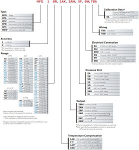
SAMPLE CATALOG LISTINGS
| Order Code | Description |
| NFA1BM,1AK,2AP,5A,6A,7BA | Model FP5000; 0.10% accuracy; 30 psi absolute; compensated across 0°C to 60°C [40°F to 140°F]; 0 Vdc to 10 Vdc output; 1/4-18 NPT female port; PT02A-10-6P 6-pin electrical connector; standard wiring; 5-point calibration data at 77°F |
| NFG2DR,1Y,2AR, 5G,6Q,7BB | Model FP5000; 0.20% accuracy; 5000 psi gage; compensated across -20°C to 80°C [0°F to 180°F]; Intrinsic Safety Certifications; 4 mA to 20 mA output; G 1/4 B male port; 5 ft long integral cable; alternative wiring; 5-point calibration data at 77°F |
| NDW1BR,1AK,2AM,5F,6A,7BA | Model FP5000; 0.10 % accuracy; 100 psi differential; compensated across 0°C to 60°C [40°F to 140°F]; 4 mA to 20 mA output; G 1/4B female port, PT02A-10-6P 6-pin electrical connector; standard wiring; 5-point calibration data at 77°F |
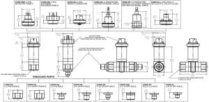
Figure 2. Mounting Dimensions
CAUTION
PRODUCT DAMAGE DUE TO MECHANICAL ISSUES
- Ensure torque specifications are determined for the specific application. Mating materials and thread sealants can result in significantly different torque values from one application to the next.
- When using mating parts made of stainless steel, use a thread sealant with anti-seize properties to prevent thread galling. Ensure the sealant is rated for the application.
- Use appropriate tools (such as an open-ended wrench or deep-well socket) to install transducers.
- Always hand-start transducers into the hole to prevent cross threading and damage.
- Ensure that torque is not applied to the electrical connector.
- Ensure that the proper mating electrical connector with a seal is used to connect the transducer. Improper or damaged seals can compromise ingress protection, leading to short circuits.
- To ensure proper environmental sealing and electrical connections when using a connector, follow the connector manufacturer’s installation guidelines.
- All terminal cavities must be sealed using the correct wire gauge and seal combination.
- If only two leads are used, any additional terminal cavities should be sealed per the connector manufacturer’s installation guide
- Honeywell recommends using a crimping tool for crimping wires to the connector terminals.
- Contact the individual connector manufacturer for connector wiring.
Failure to comply with these instructions could result in product damage.
NOTICE
Refer installation manual #008-0751-00 for installation/ wiring instructions, cautions and warnings related to Intrinsically Safe FP5000 (option 2AR).
WARNING
PERSONAL INJURY
- DO NOT USE these products as safety or emergency stop devices or in any other application where failure of the product could result in personal injury.
Failure to comply with these instructions could result in death or serious injury.
WARNINGMISUSE OF DOCUMENTATION
- The information presented in this product sheet is for reference only. Do not use this document as a product installation guide.
- Complete installation, operation, and maintenance information is provided in the instructions supplied with each product.
Failure to comply with these instructions could result in death or serious injury.
Warranty/Remedy
Honeywell warrants goods of its manufacture as being free of defective materials and faulty workmanship during the applicable warranty period. Honeywell’s standard product warranty applies unless agreed to otherwise by Honeywell in writing; please refer to your order acknowledgment or consult your local sales office for specific warranty details.If warranted goods are returned to Honeywell during the period of coverage, Honeywell will repair or replace, at its option, without charge those items that Honeywell, in its sole discretion, finds defective. The foregoing is buyer’s sole remedy and is in lieu of all other warranties, expressed or implied, including those of merchantability and fitness for a particular purpose. In no event shall Honeywell be liable for consequential, special, or indirect damages.
While Honeywell may provide application assistance personally, through our literature and the Honeywell website, it is buyer’s sole responsibility to determine the suitability of the product in the application.
Specifications may change without notice. The information we supply is believed to be accurate and reliable as of this writing. However, Honeywell assumes no responsibility for its use.
FOR MORE INFORMATION
Honeywell Advanced Sensing Technologies services its customers through a worldwide network of sales offices and distributors. For application assistance, current specifications, pricing, or the nearest Authorized Distributor, visit sps.honeywell.com/ast or call:
USA/Canada: +302 327 8920Latin America: +1 305 805 8188Europe: +1 302 327 8920Japan: +81 (0) 3-6730-7152Singapore: +65 6355 2828Greater China: +86 4006396841

References
[xyz-ips snippet=”download-snippet”]