Honeywell FSS-SMT Sensor Evaluation Board Instructions
1.0 OVERVIEW
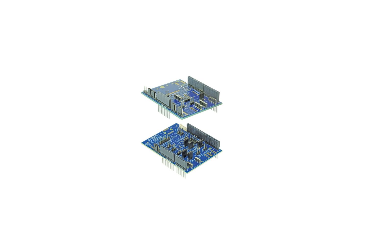
The Honeywell Sensor Evaluation Board (SEB) is an Arduino™ UNO stackable shield that allows evaluation of all Honeywell force sensors and ABP2 Series pressure sensors. Sensor capabilities can be demonstrated and evaluated. In some cases, the evaluation board can be used as part of a prototype.
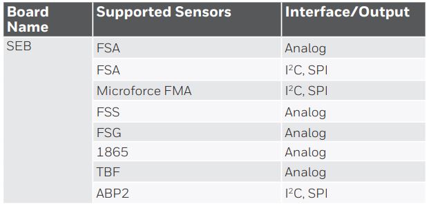
The SEB, along with the readily available components shown in Table 1, and the free evaluation software, comprise a simple set of components used to evaluate the sensors listed in Table 2.
The SEB assembly allows the user to obtain sensor readings without needing to develop any code. The Desktop Application controls the Arduino board to take sensor readings and display them on the screen.
The readings may also be recorded to a .csv file for further analysis.
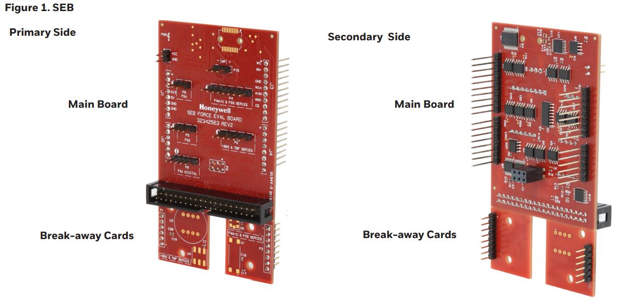
Sensors can be mounted on the SEB break-away cards and wired to the SEB main board via jumper wires, or sensors can be connected to SEB main board directly using jumper wires
2.0 SEB AND USER-PROVIDED COMPONENTS
2.1 Assemble Components shown in Table 1.
Create required assembly from the components shown in Table 1.
TABLE 1. SENSOR EVALUATION KIT CONTENTS AND USER-PROVIDED ITEMSHONEYWELL SENSOR EVALUTION KIT, SEB
Includes:
- Sensor Evaluation Board
USER-PROVIDED COMPONENTS
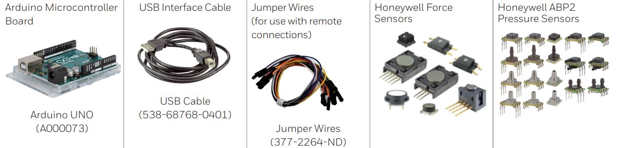
TABLE 2. HONEYWELL FORCE SENSORS THAT CAN BE USED WITH SEB
SENSOR
DESCRIPTION
FSS SeriesThe FSS Series force sensor provides precise, reliable force sensing performance in a compact, commercial-grade package. The sensor features a proven sensing technology that uses a specialized piezo resistive, micromachined silicon sensing element. The low power, unamplified, uncompensated Wheatstone bridge circuit design provides inherently stable mV outputs over the force range.https://sps.honeywell.com/us/en/products/sensing-and-iot/sensors/force-sensors/fss-series
FSS SMT SeriesHoneywell FSS-SMT Series force sensors are unamplified, uncompensated sensors. This low profile surface mount technology (SMT) sensor allows for automated assembly on a printed circuit board.https://sps.honeywell.com/us/en/products/sensing-and-iot/sensors/force-sensors/fss-smt-series
FSG SeriesThe FSG Series force sensor provides precise, reliable force sensing performance in a compact commercial grade package. The sensor features a proven sensing technology that utilizes a specialized piezo resistive micromachined silicon sensing element. The low power, unamplified, non-compensated Wheatstone bridge circuit design provides inherently stable mV outputs over the 5 N, 10 N, 15 N and 20 N force ranges.https://sps.honeywell.com/us/en/products/sensing-and-iot/sensors/force-sensors/fsg-series
FSA SeriesThe FSA Series are piezo resistive-based force sensors offering a radiometric analog or digital output for reading force over the specified full scale force span and temperature range. They are fully calibrated and temperature compensated for sensor offset, sensitivity, temperature effects and nonlinearity using an on-board Application Specific Integrated Circuit (ASIC). Direct mechanical coupling allows for easy interface with the sensor, coupling with tubing, membrane or a plunger, providing repeatable performance and a reliable mechanical interface to the application.https://sps.honeywell.com/us/en/products/sensing-and-iot/sensors/force-sensors/fsa-series
Basic TBF SeriesBasic TBF Series force sensors are small flush diaphragm pressure sensors designed for customers who require a simple device for applications where media compatibility and low trapped volume are important. The TBF Series is an unamplified, but compensated sensor.https://sps.honeywell.com/us/en/products/sensing-and-iot/sensors/force-sensors/basic-tbf-series
1865 SeriesThe 1865 Series is a high-performance transducer specifically designed to address the needs of medical and specialized OEM applications. Offering laser-trimmed compensation, these products may be specified to operate with either a constant current or voltage supply. The 1865 Series is a compensated, unamplified series.https://sps.honeywell.com/us/en/products/sensing-and-iot/sensors/force-sensors/1865-series
Microforce FMA SeriesThe FMA Series are piezo resistive-based force sensors offering a digital output for reading force over the specified full scale force span and temperature range. They are fully calibrated and temperature compensated for sensor offset, sensitivity, temperature effects, and nonlinearity using an on-board Application Specific Integrated Circuit (ASIC). The FMAMSDXX005WCSC3, FMAMSDXX005WC2C3 and FMAMSDXX015WCSC3 are available on a breakout board.https://sps.honeywell.com/us/en/products/sensing-and-iot/sensors/force-sensors/microforce-fma-series
ABP2 SeriesThe ABP2 Series are I2C or SPI digital output sensors available in pressure ranges of 4 in-H2O to 175 psi. They are fully calibrated and temperature compensated for sensor offset, sensitivity, temperature effects and non-linearity using an on-board Application Specific Integrated Circuit (ASIC).https://sps.honeywell.com/us/en/products/sensing-and-iot/sensors/pressure-sensors/board-mountpressure-sensors/basic-abp2-series
2.2 Review Sensor Connection Methods
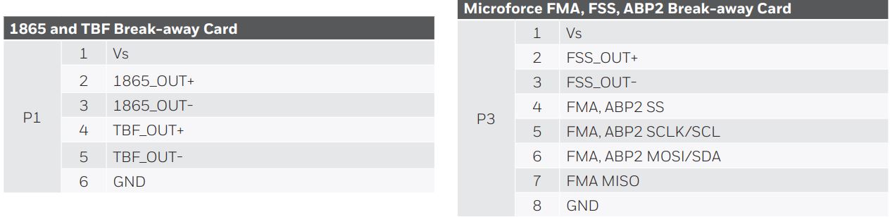
(Please note that a white dot on the card indicates connector pin 1, or pin 1 of the sensor being inserted on the break-away card.)
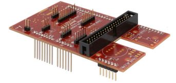
Part 1 – Break-away Cards (Pinout): Mount sensors directly on the SEB main board break-away cards. This allows the sensor to be tested in the normal mounting means. Use the jumper wires to match pins from the break-away card to the appropriate port and equivalent pins on the SEB (see Part 2 table). Please see the Honeywell Technical Note for the recommended SMT handling procedure for additional soldering instructions such as stencil design, etc. Please consult the FMA Series datasheet for availability for a break-out board that greatly simplifies sensor mounting and provides an in-lead termination to assist in connecting to the device.
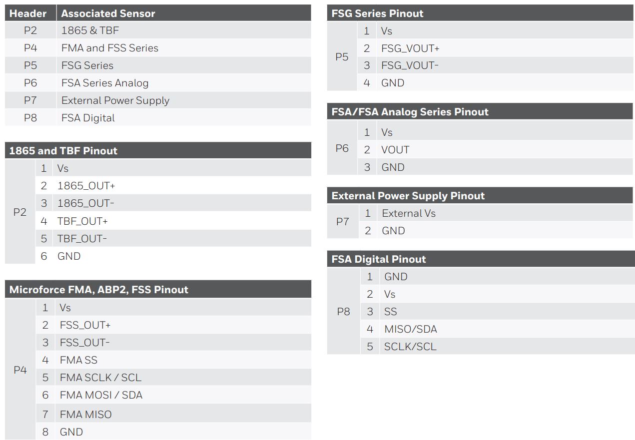
Part 2 – SEB Main Board (Pinout): Connect sensors to the SEB main board using jumper wires from pins on the break-away cards, or directly to legs on the sensor. This could be for proof of concept in preparation for testing/implementation with a break-away card.
2.3 Connect the sensor to be evaluated to the SEB Main Board
Connect the sensor to the break-away card, then with jumper wires to the SEB main board using pinout from section 2.2. Or, it can also be connected directly from pins on the sensor to be tested to the appropriate header on the SEB main board using pinout from section 2.2.
2.4 Connect the SEB to the Arduino UNO
Place the SEB over the Arduino Uno board and align all pins and sockets. Gently press both boards together until the SEB is seated on top of the Arduino board (see Figure 2 below).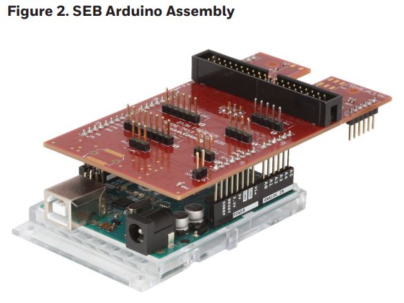
3.0 SOFTWARE INSTALLATION
3.1 Installation of PC and Laptop Software and Drivers or Smartphone App
The desktop application installation includes necessary software drivers for the Arduino UNO board.Please follow these instructions to obtain and load the required software.Before installing, be sure to remove any earlier versions by using the uninstall programs feature on your computer.
3.1.1 System Requirements
- Operating system Microsoft® Windows® 7 or Windows® 10, 64 bit
- The screen must support and be set for a resolution of 800 x 600 or higher
3.1.2 Loading PC or Laptop Software and Device Drivers
This step is required only when the SEB assembly is connected to a USB port for the first time.
- Connect the Arduino/SEB assembly to the PC or laptop. Refer to Table 1 and sections 2.3 and 2.4 to identify correct Arduino board and USB cable.
- Download the required SEB software and device drivers from the following URL:https://sps.honeywell.com/us/en/products/sensingand-iot/sensors/sensor-evaluation-kits/sensorevaluation-kits
- Unzip the downloaded file to a location on the computer or laptop.
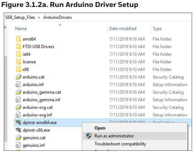
- Navigate to that location, open the subfolder named Arduino Drivers, and find the correct setup file:• dpinst-amd64.exe – for 64-bit system• dpinst-x86.exe for 32-bit system
- For most computers, the drivers will load automatically. But if this is an issue, please perform the following steps. Otherwise, go to step 3.1.2d.
- Load Arduino drivers by right-clicking the correct file and selecting Run as administrator.
 If asked to Accept a license agreement, select the radio button and click Next.
 - At the Welcome screen, click Next.
- Allow the device driver installation to run. Drivers will display as Ready to use when installation is complete. Click Finish.
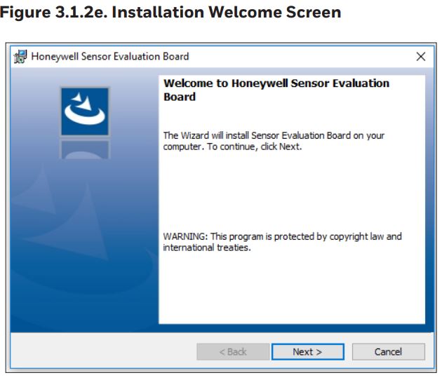
- Return to the main install folder. Right-click the Setup.exe file, and select Run as administrator to start the Desktop Application installation.
- Observe the Welcome screen, and click the Next button.
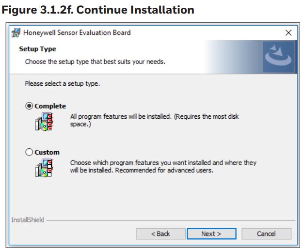
- Click the Complete radio button to install all program features and drivers, then click the Next button.To modify any of the defaults, such as installation directory, click the Custom radio button and then click the Next button. Make modifications as desired and continue.
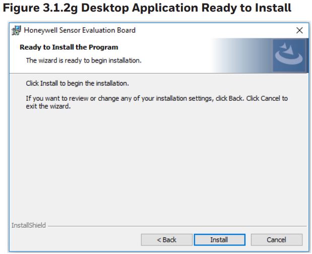
- Observe the Ready to Install screen, and click the Install button.
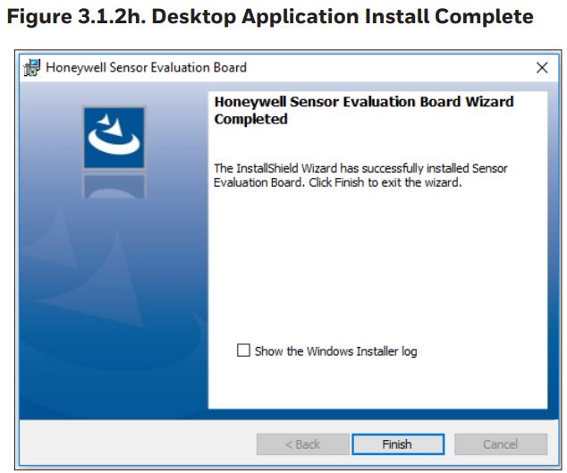
- The Desktop Application install completes. Click the Finish button.
 If asked to Accept a license agreement, select the radio button and click Next.
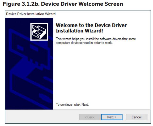
3.2 Launch the Desktop Application
3.2.1 Verify Connections
- Using the desktop application, verify that the SEB assembly is connected to the PC or laptop.
3.2.2 Launch Application
- Using a PC or laptop, launch the Sensor Evaluation Board desktop application on the PC.
4.0 USING THE SOFTWARE
4.1 Sensor Selection
- If device drivers were loaded during initial setup, the desktop application recognizes the SEB assembly.
- When the desktop application automatically recognizes the SEB assembly, it also selects it as the Host Board Type.
- The Device Status will show green rather than red to indicate the application is communicating with the assembly.
- Arduino firmware is verified by the desktop application, which also gives a provision to flash the current or new version if desired. Flashing firmware isn’t necessary if version is correct.
The firmware flashing can be found under flashing detail in the pull down to the right and is initiate by clicking on the browse and flash firmware . The path is then selected by the user to the location it was saved on the hard drive (see Table 5).
TABLE 3. USING THE SOFTWARESTEP 1.
- Connect SEB assembly to PC or laptop.
- Open desktop application.
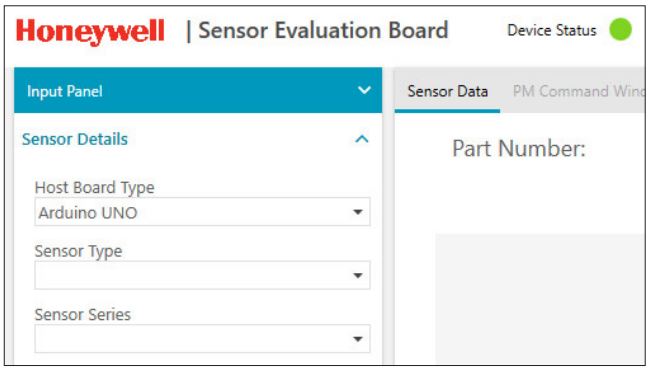
- Verify correct Host Board Type appears and that Device Status light is green. Select correct Host Board Type, if necessary.
2.
- If desired part number configuration appears as a recent Part Number selection, select it.
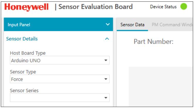
- Otherwise, select Force or Pressure from the Sensor Type dropdown.
TABLE 3. USING THE SOFTWARE (CONT.)STEP 3.
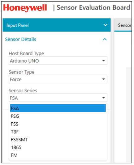
- Select desired series from the Sensor Series dropdown.
4.
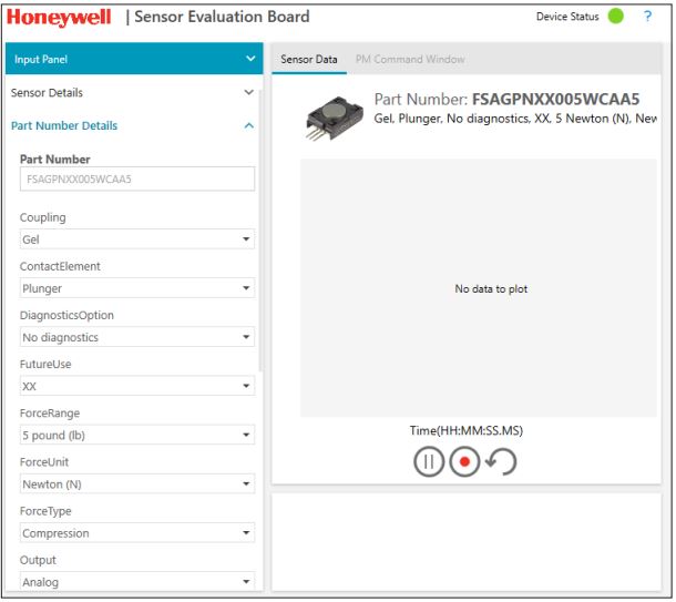
- Click in the Part Number field.
- Start entering desired part number. As you type, valid part numbers appear in a dropdown.
- Pick the desired listing. Appropriate options appear. A description of the part number shows in the window, select from the drop down menu.
- Complete missing option selections, or change existing ones. This includes SEB power supply, and required test set- tings under Settings.
- Click Apply Configuration.
TABLE 4. TEST AND OUTPUTSTEP 1.
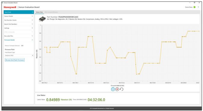
- Start and run the test using the bottom of the Sensor Data window. Start, stop and save data for comparison with other test runs.
TABLE 5. FIRMWARE DETAILS FLASH FIRMWARE TO ARDUINO BOARD ANYTIMESTEP 1.
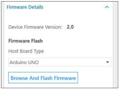
Verify and flash SEB software to the Arduino board anytime using the firmware details option on the desktop application input panel.
- Open the option to view the firmware version currently running on selected Host Board Type.
- Select Browse And Flash Firmware to re-flash the current version, or flash an update.
- Occasionally, firmware updates may be released to the website. Download the necessary .Hex file for use with this flashing application.
TABLE 6. SENSOR SELECTION PANEL SCREEN FUNCTIONS
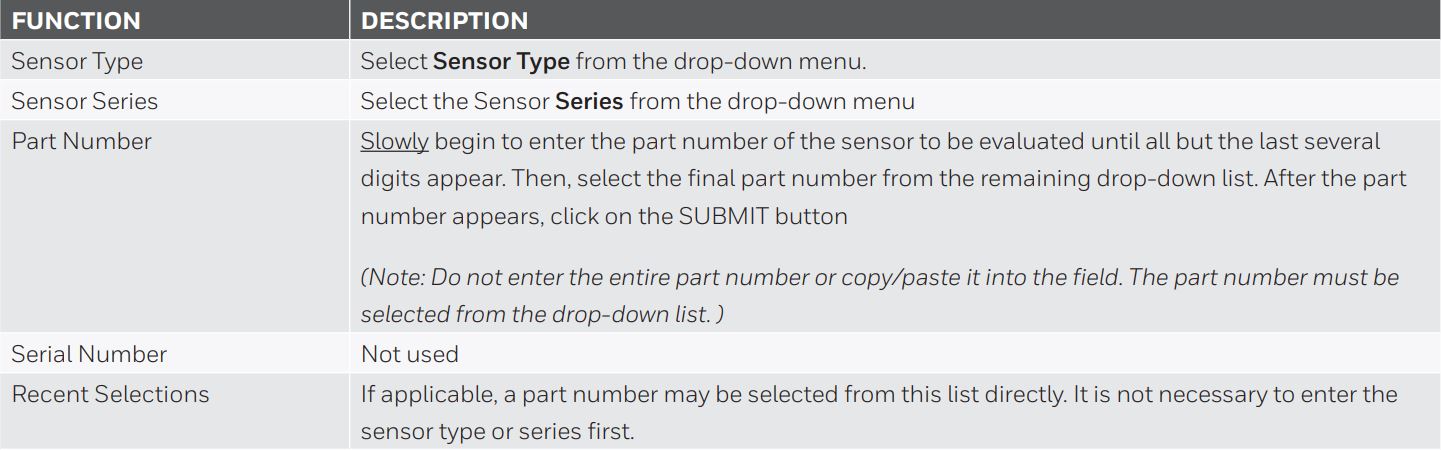
TABLE 7. SETTINGS
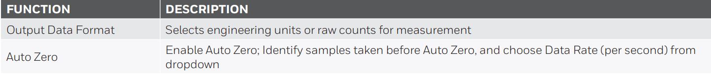
TABLE 8. HELP SCREEN FUNCTIONS

WARRANTY/REMEDY
Honeywell warrants goods of its manufacture as being free of defective materials and faulty workmanship during the applicable warranty period. Honeywell’s standard product warranty applies unless agreed to otherwise by Honeywell in writing; please refer to your order acknowledgment or consult your local sales office for specific warranty details. If warranted goods are returned to Honeywell during the period of coverage, Honeywell will repair or replace, at its option, without charge those items that Honeywell, in its sole discretion, finds defective. The foregoing is buyer’s sole remedy and is in lieu of all other warranties, expressed or implied, including those of merchantability and fitness for a particular purpose. In no event shall Honeywell be liable for consequential, special, or indirect damages.
While Honeywell may provide application assistance personally, through our literature and the Honeywell web site, it is buyer’s sole responsibility to determine the suitability of the product in the application.
Specifications may change without notice. The information we supply is believed to be accurate and reliable as of this writing. However, Honeywell assumes no responsibility for its use.
![]() WARNINGMISUSE OF DOCUMENTATION
WARNINGMISUSE OF DOCUMENTATION
- The information presented in this product sheet is for reference only. Do not use this document as a product installation guide.
- Complete installation, operation, and maintenance information is provided in the instructions supplied with each product.
Failure to comply with these instructions could result in death or serious injury.
![]() WARNINGPERSONAL INJURYDO NOT USE these products as safety or emergency stop devices, or in any application where failure of the product could result in personal injury.Failure to comply with these instructions could result in death or serious injury.
WARNINGPERSONAL INJURYDO NOT USE these products as safety or emergency stop devices, or in any application where failure of the product could result in personal injury.Failure to comply with these instructions could result in death or serious injury.
FOR MORE INFORMATION
Honeywell Advanced Sensing Technologies services its customers through a worldwide network of sales offices and distributors. For application assistance, current specifications, pricing or the nearest Authorized Distributor, visit our website or call:
USA/Canada +1 302 613 4491Latin America +1 305 805 8188Europe +44 1344 238258Japan +81 (0) 3-6730-7152Singapore +65 6355 2828Greater China +86 4006396841
Honeywell Advanced Sensing Technologies830 East Arapaho Road Richardson, TX 75081 sps.honeywell.com/ast
Arduino is a trademark or registered trademark of Arduino, LLC in the United States and/or other countries.Microsoft® and Windows® are either registered trademarks or trademarks of Microsoft Corporation in the United States and/or other countries.3000-0210-001-A-EN | 1 | 07/21 © 2021 Honeywell International Inc.
![]()
References
FSA Series Force Sensors | Honeywell LinkedIn Facebook Twitter YouTube
1865 Series Force Sensors | Honeywell LinkedIn Facebook Twitter YouTube
Products – Advanced Sensing Technologies | Honeywell
Basic TBF Series Force Sensors | Honeywell LinkedIn Facebook Twitter YouTube
FSS-SMT Series Force Sensors | Honeywell LinkedIn Facebook Twitter YouTube
MicroForce FMA Series | Force Sensors | Honeywell LinkedIn Facebook Twitter YouTube
FSG Series Force Sensors | Honeywell LinkedIn Facebook Twitter YouTube
FSS Series Force Sensors | Honeywell LinkedIn Facebook Twitter YouTube
[xyz-ips snippet=”download-snippet”]