
Honeywell Gas Conversion Kits Installation Instructions
This is a legacy product document supported by Resideo. It is no longer manufactured
396206-1, -2 Gas Conversion Kits for RV8310E Millivolt Receiver/Modulating Gas Valve
APPLICATION
The 396206-1 Natural Gas Conversion Kit changes the RV8310E from regulated LP gas to regulated natural gas. The 396206-2 LP Conversion Kit changes the RV8310E from regulated natural gas to regulated LP gas. The kits include a fuel conversion plug (blue for natural gas, red for LP gas) and a conversion label.
INSTALLATION
When Installing This Product…
- Read these instructions carefully. Failure to follow the instructions can damage the product or cause a hazardous condition.
- Check ratings given in the instructions and on the product to make sure the product is suitable for your application.
- The installer must be a trained, experienced service technician.
- After installation is complete, check out product operation using these instructions.
![]() WARNING
WARNING
Fire or Explosion Hazard. Can cause property damage, severe injury or death.
Follow these warnings exactly:
- Disconnect power supply before wiring to prevent electrical shock or equipment damage.
- To avoid dangerous accumulation of fuel gas, turn off gas supply at appliance service valve before starting installation and perform Gas Leak Test after completion of installation.
- Use only your hand to turn the gas control knob. Never use any tools. If the gas control knob will not operate by hand, then a qualified technician should replace the gas control. Force or attempted repair may result in fire or explosion.
- Change main and pilot burner orifices to meet appliance manufacturer specifications.
Conversion to LP Gas (396206-2 Conversion Kit)
- Turn off the gas supply at the appliance service valve.
- Remove the motor cover (see Fig. 1).
- Using a common screwdriver, push the gas selector knob down and turn the knob until the pointer is at the red-colored screw.
- Release the knob.
- Remove the natural gas (NG) fuel conversion plug and insert the LP fuel conversion plug.
- Attach the LP conversion label to the upper right side of the valve, next to the product label.
- Replace the motor cover.
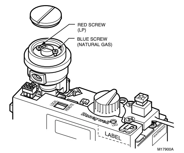
Fig. 1. RV8310E Millivolt Receiver/Modulating Gas Valve, showing motor cover removed and location of conversion plug and conversion label.
Conversion to Natural Gas (396206-1 Conversion Kit)
- Turn off the gas supply at the appliance service valve.
- Remove the motor cover (see Fig. 1).
- Using a common screwdriver, turn the selector knob until the arrows point at the blue-colored screw and the selector knob pops up.
- Release the knob.
- Remove the LP fuel conversion plug and insert the natural gas (NG) fuel conversion plug.
- Attach the natural gas conversion label to the upper right side of the valve, next to the product label.
- Replace the motor cover.
IMPORTANT
The high and low outlet pressure settings for natural gas and LP gas cannot be changed on the RV8310.
OPERATION
![]() WARNING
WARNING
Fire Hazard.Can cause severe injury or death.Moving the LOCAL/REMOTE switch can cause the main burner to come on immediately. Stand away from the main burner when moving the LOCAL/REMOTE switch.
Startup
- Turn the gas control knob counterclockwise from OFF to the PILOT position.
- Push the knob down and hold in position. The pilot valve opens and allows gas to flow to the pilot burner.
- Push the plunger on the piezo until the pilot burner is lit. When the pilot burner is lit, the LED on the control will come on after approximately 60 seconds and will blink continuously.
- Release the gas control knob. the shaft moves upward and the pilot burner stays burning. If the pilot burner goes out, repeat steps 2 and 3.
- Turn the gas control know counterclockwise to the ON position. If the manual switch is in the LOCAL position, the main burner will come on immediately.
On the initial use of a transmitter, a recognition operation is required between the receiver/valve and the transmitter.
- Move the LOCAL/REMOTE switch to the LOCAL position for at least two seconds; then move the switch to the REMOTE position.
- Press the FAN or FLAME button on the transmitter within 30 seconds of the switch change.
The LED will blink indicating that the transmitter will now work with the receiver/valve. If the switch stays in the REMOTE position, the RT8220A Transmitter will control the main valve, flame modulation level and fan control.
If the LOCAL/REMOTE switch is in the LOCAL position, the receiver/valve will be a the highest fixed pressure setting.
Shut-Off Procedure
If the LOCAL/REMOTE switch is in the REMOTE position, the RT8220A Transmitter can shut off the main burner and fan. However, the control is still on and a command from the transmitter can turn on the main burner and fan.
To shut off the system:
Turn the gas control knob clockwise to the OFF position.This closes the main gas and safety valves. The transmitter cannot turn on the main burner or the fan.
CHECKOUT
![]() WARNING
WARNING
Fire or Explosion Hazard.Can cause property damage, severe injury or death.Do not force the gas control knob on the appliance. use only your hand to turn the gas control knob. If the knob does not operate by hand, the valve should be replaced by a qualified service technician.
Gas Control Knob Settings
Gas control knob settings are as follows:
OFF: Prevents main gas flow through the valve.
ON: Permits main burner and pilot gas flow. Gas valve and RT8220A Transmitter control main burner gas flow.
PILOT: Opens pilot valve and allows gas flow to the pilot burner.
NOTE: Valves are shipped with the gas control knob in the ON position.
Perform Gas Leak Test
![]() WARNING
WARNING
Fire or Explosion Hazard.Can cause property damage, severe injury or death.Stand away from the main burner when lighting. Hidden gas leaks can cause flashback in the appliance vestibule. Check for gas leaks with rich soap and water solution any time work is done on a gas system.
Gas Leak Test
- Paint the pipe connections upstream of the gas valve with the rich soap and water solution. Bubbles indicate a gas leak.
- If a leak is detected, tighten the pipe connections.
- Light the main burner.
- With the main burner in operation, paint the pipe joints (including adapters) and valve inlet and outlet with a rich soap and water solution.
- If another leak is detected, tighten the adapter screws, joints, and pipe connections.
- Replace the part if the leak cannot be stopped.
Turn on System
Rotate the gas control knob counterclockwise to ON.
Turn on Main Burner
Follow the instructions provided by the appliance manufacturer or use the RT8220A Transmitter. This product does not have a High/Low knob.
Check and Adjust Gas Input and Burner Ignition
IMPORTANT
Do not exceed the input rating stamped on the appliance nameplate, or the manufacturer recommended burner orifice pressure for size orifice(s) used.
IMPORTANT
For complete combustion, be sure the primary air supply to the main burner is adjusted properly. Follow the instructions of the appliance manufacturer.
CHECKING GAS INPUT BY CLOCKING GAS METER
- Be sure there is no gas flow through the meter except to the appliance being checked.NOTE: Other appliances must remain off with the pilots extinguished, or the consumption must be deducted from the meter reading.
- Convert the flow rate to Btuh as described in the Gas Controls Handbook, form 70-2602.
- Compare to the Btuh input rating on the appliance nameplate.
CHECKING GAS INPUT WITH MANOMETER
NOTE: Both the inlet and outlet pressure taps have a captive screw.
- Be sure the gas control knob is in the PILOT position.
- Loosen, but do not remove the outlet tap captive screw.
- Attach a plastic tube with a 1/4 in. shell ID and connect the manometer.
- Turn the gas control knob to the ON position.
- Check the outlet tap pressure.
- Turn the gas control knob to the OFF position.
- Shut off the gas supply at the manual valve in the gas piping to the appliance or, for LP, at the tank.
- Loosen but do not remove the inlet tap captive screw.
- Attach a plastic tube with a 1/4 in. shell ID and connect the manometer.
- Turn on the gas supply at the manual valve.
- Check the inlet tap pressure.
- Turn the gas control knob to the OFF position.
- Repeat the Gas Leak Test at the pressure tap with the main burner operating.
- Always tighten the screws in the pressure taps after disconnecting the plastic tubes.

® U.S. Registered TrademarkCopyright © 2002 Honeywell ï All Rights Reserved
![]()
Automation and Control Solutions
Honeywell1985 Douglas Drive NorthGolden Valley, MN 55422
Honeywell Limited-Honeywell Limitée35 Dynamic DriveScarborough, OntarioM1V 4Z9
![]() Printed in U.S.A. on recycled paper containing at least 10% post-consumer paper fibers.
Printed in U.S.A. on recycled paper containing at least 10% post-consumer paper fibers.
[xyz-ips snippet=”download-snippet”]