![]()

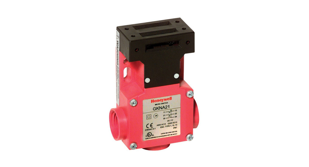
Installation Instructions for theGKN Series Multi-Entry Key Operated Safety Interlock Switch
![]() WARNING
WARNING
IMPROPER INSTALLATION
- Consult with local safety agencies and their requirements when designing a machine-control link, interface, and all control elements that affect safety.
- Strictly adhere to all installation instructions. Failure to comply with these instructions could result in death or serious injury.
MOUNT, WIRE, SEAL, AND TEST SWITCH
WARNINGIMPROPER OPERATION
- Ensure key travels to the given minimum insertion distance to ensure switch contact transfer.
- Ensure key travels to maximum extraction distance to ensure the correct operation of the positive brake mechanism.
- Do not exceed 50 N [11.2 lb] actuation force.
- Do not use the key as a stop for the door.Failure to comply with these instructions could result in death or serious injury.
- Refer to:
- Page 6 for specifications.
- Page 7 for switch mounting.
2. Ensure proper clearance for the switch and key at the mounting location.3. Align the switch and key together before mounting.4. Mount switch and key:
- Torque switch to the mounting surface: 1,0 N m-1,4 N m [9 in lb-12 in lb] using M5 screws
- Torque key to the mounting surface: 1,0 N m-1,4 N m [9 in lb-12 in lb] using M4 or M5 screws
- Care should be taken to ensure that all mounted hardware cannot become detached during the operational lifetime in the intended application
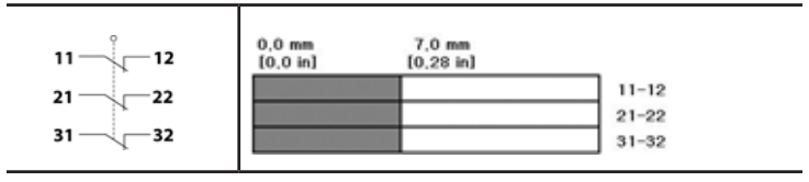
5. Refer to the circuit diagram on switch housing. Diagram depicts a safety switch when the key is inserted.
6. Remove screws on the cover plate.7. The three conduit openings have been molded using knockout. Break out the conduit opening required for use.8. Connect stranded wire (0,75 mm 2 to 2,5 mm 2, 18 AWG- 14 AWG) or solid wire (0,75 mm 2 – 1,5 mm 2 , 18 AWG16 AWG) to connector terminals (Use copper wire only, minimum 75 °C rated):
- Torque switch terminal screws: 0,8 Nm to 1,0 N m [7 in lb-9 in lb] M3
- Torque connector to secure the cable to switch enclosure (if required): 1,8 Nm to 2,2 N m [16 in lb-19 in lb]
9. Seal conduit opening according to instructions in PK 80112.10. Reassemble cover plate with cover screw. Torque to0,40 Nm to 0,50 Nm [3.5 in-lb to 4.5 in-lb].11. Perform functional tests:
- Open and close protective guard several times to confirm key slides easily into switch head
- Open and close protective guard several times to confirm switch contacts transfer (change state) in each state
- Confirm the normally closed contacts open when the protective guard is open
- Confirm hazardous motion does not start when the protective guard is open
GKN Series
| Designation and Utilization Category | Rated Operational Current le (A) at Rated Operational Voltage Ue (V) | |||
| 120 Vac |
240 Vac/250 Vdc |
600 Vac | ||
| AC15 | A600 | 1,2 A | 3 A | |
| DC13 | Q300 | 0,55 A | 0,27A | — |
| Rated thermal current (Ith) | 10 A | Sealing | I P67; NEMA 1, 4X indoor use only, 12, 13 | |
| Rated impulse withstand (Uimp) | 2500 V | Pollution degree | 2 (micro-environment, inside enclosure);
3 (macro-environment, installation environment) |
|
| Rated insulation voltage (Ui) | 600 V | Operating temperature range | -25 °C to 70 °C [-13 °F to 158 °F] | |
| Short-circuit protective device (type/ maximum rating) | Class J fuse (10 A/600 V) | Storage temperature range | -40 °C to 85 °C [-40 °F to 185 °F] | |
| Conditional short-circuit current | 1000 A | Expected mechanical life | 500,000 operations |
Complies with:
- Low Voltage Directive 73/23/EEC, as amended by directive 93/68/EEC.
- Machinery Directive 98/37/EEC only as the directives relate to the components being used in a safety function.
- IEC/EN60947-5-1.
MCTF (Mechanical Life): >1,000,000 cycles with single-sided confidence limit of 100 %MCTF (Electrical Life): >25,000 cycles with single-sided confidence limit of 75 %Highest SIL Capability: SIL3 (HFT:1), IEC 61508-2: 2010; Proof Test Interval: 1 Year
Designation and utilization categoryRated operational current Ie (A) at rated operational voltage Ue (V)Rated thermal current (Ith)Rated impulse withstand (Uimp)Rated insulation voltage (Ui)Short-circuit protective device (type/maximum rating)Conditional short-circuit currentSealingPollution degreeOperating temperature rangeStorage temperature rangeMechanical lifeComplies with:· Low Voltage Directive 73/23/EEC, as amended by directive93/68/EEC.·Machinery Directive 98/37/EEC only as the directives relate to the components being used in a safety function.·IEC/EN60947-5-1.MCTF (Mechanical Life): >1,000,000 cycles with single-sided confidence limit of 100 %MCTF (Electrical Life): >25,000 cycles with single-sided confidence limit of 75 %Highest SIL Capability: SIL3 (HFT:1), IEC 61508-2: 2010; Proof Test Interval: 1 Year
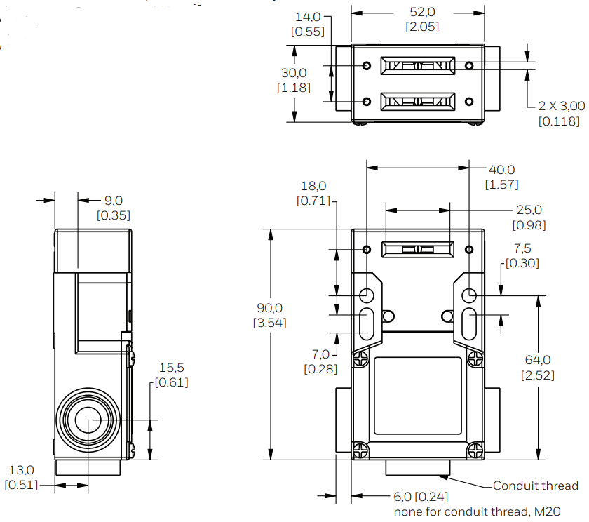
MOUNTING DIMENSIONS (MM/IN)
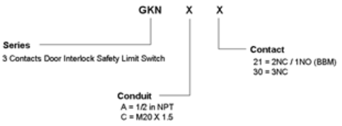
PART NUMBER TREE
CIRCUIT AND TRAVEL DIAGRAMS
Switch Code 21 – 2 NC/1NO BBM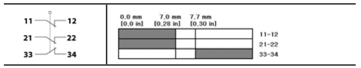
Switch Code 30 – 3 NC
SWITCH ORDER GUIDE (ACTIVE LISTINGS
|
Description |
| 3 contact door interlock safety limit switch;1/2 in NPT conduit; 2NC/1NO (BBM) |
| 3 contact door interlock safety limit switch; 1/2 in NPT conduit; 3NC |
| 3 contact door interlock safety limit switch; M20 x 1.5 conduit; 2NC/1NO (BBM) |
| 3 contact door interlock safety limit switch; M20 x 1.5 conduit; 3NC |
| Straight key |
| 90° key |
| Left-right adjustable key |
| Up-down adjustable key |
| Multidirectional key |
| Funnel key |
SWITCH ORDER GUIDE (ACTIVE LISTINGS)
| Min. Actuating Radius |
| min. R 160 [6.30] |
| min. R 160 [6.30] |
| min. R 32 [1.26] |
| min. R 45 [1.77] |
| Moveable max. 18 degrees |
| min. R 160 [6.30] |
Warranty
Honeywell warrants goods of its manufacture as being free of defective materials and faulty workmanship during the applicable warranty period. Honeywell’s standard product warranty applies unless agreed to otherwise by Honeywell in writing; please refer to your order acknowledgment or consult your local sales office for specific warranty details. If warranted goods are returned to Honeywell during theperiod of coverage, Honeywell will repair or replace, at its option, without charge those items that Honeywell, in its sole discretion, finds defective. The foregoing is the buyer’s sole remedy and is in lieu of all other warranties, expressed or implied, including those of merchantability and fitness for a particular purpose. In no event shall Honeywell be liable for consequential, special, or indirect damages.While Honeywell may provide application assistance personally, through our literature and the Honeywell website, it is the buyer’s sole responsibility to determine the suitability of the product in the application.Specifications may change without notice. The information we supply is believed to be accurate and reliable as of this writing. However, Honeywell assumes no responsibility for its use.
Email: [email protected]Internet: sensing.honeywell.comAsia Pacific+65 6355-2828+65 6445-3033 FaxUSA/Canada+1-800-537-6945+1-815-235-6847+1-815-235-6545Fax
Honeywell Advanced Sensing Technologies830 East Arapaho RoadRichardson, TX 75081sps.honeywell.com/ast
TORX® is a registered trademark of the Camcar Corp. division of Textron IndsTeflon™ is a registered trademark and a brand name owned by Chemours 50017382-12-ML | 12 | 04/21© 2021 Honeywell International Inc. All rights reserved.
References
[xyz-ips snippet=”download-snippet”]