![]()
HE360 Humidifier andInstallation KitThis is a legacy product document supported by Resideo. It is no longer manufacturedINSTALLATION INSTRUCTIONS
WELCOME
To the comfortable world of humidified air. When you use your Honeywell humidifier, notice that your skin is not as dry, and that your scratchy throat and irritated nasal passages that aggravate allergies and asthma are steadily improving.You have also taken the first step in reducing the zapping you create when you walk on your carpet and then touch your TV, computer, metal doorknob or your pet. Your furniture and woodwork are also benefitting from the difference that humidified air makes.Congratulations! You have just made a great investment in improving the comfort of your home.
APPLICATION
This kit contains your new Honeywell HE360 Humidifier, H8908 Humidistat and all the accessories required for installation.
INSTALLATION
Preparing for the Installation Be sure to identify all the required (Table 1) accessories (included) and make sure the appropriate tools are available before beginning the installation.
Required Accessories (Included)Required ToolsTable 1. Required Accessories.
| Quantity | Accessory (Item Quantity) |
| Humidifier Parts and Accessories | |
| 20 ft(6.2m) | 18 gauge, two-strand thermostat wire |
| 20 ft(6.2m) | 1/4 in. (6.35 mm) OD feedwater tubing |
| 10 ft(3.1m) | 1/2 in (12.7 mm) ID drain tubing |
| 1 bag | Connecting and mounting hardware:Wire nuts (4) No.8 sheet metal screws (18)Drain tube clampFeed tube mounting clamps (6)Brass inserts (2)Plastic compression rings (2) |
| 1 | H8908 Humidistat |
| 1 bag | Saddle Valve Assembly:Saddle valve and top clamp (1) Threaded bottom clamp (1) Bolts (2)Rubber gasket (1)Brass insert (1)Plastic bushing (1) |
Table 1. Required Accessories.
| Quantity | Accessory (Item Quantity) |
| Air Pressure Switch and Accessories | |
| 2 | Black rubber gasket |
| 2 | Tubing Fitting Elbow |
| 10 ft (3.1m) | Tubing, 1/4 in. ID |
| 1 | Differential Pressure Switch |
| 2 | Screws, #8 x 3/4 in. sheet metal |
| 2 | Terminal Adaptor |
Tools required for installation include:
- Tin snip.
- Screwdriver.
- Adjustable or open-end wrench.
- Drill, punch or awl.
- Level.
- 3/4-in. Sheet Metal Drill Bit
Determining Best Location for Humidifier![]() CAUTIONTemperature and Static Pressure Hazard.Can cause property or equipment damage.Locate a humidifier where the ambient temperature is between 32°F (0°C) and 160°F (71°C).Do not install a humidifier where freezing temperatures could occur.Be sure supply plenum static pressure is no greater than 0.4 in. wc and water pressure is no greater than 124 psi.
CAUTIONTemperature and Static Pressure Hazard.Can cause property or equipment damage.Locate a humidifier where the ambient temperature is between 32°F (0°C) and 160°F (71°C).Do not install a humidifier where freezing temperatures could occur.Be sure supply plenum static pressure is no greater than 0.4 in. wc and water pressure is no greater than 124 psi.
- Select a location for the humidifier on the supply (warm air stream) plenum. See Fig. 1.
- Select a location that cannot damage the air conditioner A-coil during installation.
- Do not locate the humidifier on the furnace body.
- Allow adequate clearance in front of and above the humidifier so you can easily remove the cover to perform routine maintenance.
— Mount the humidifier at least 3 in. (78 mm) above the furnace body to allow adequate space for the solenoid valve and drain line.— Mount the humidifier in a conditioned space to prevent freezing.

Selecting Water Supply Location
- Use either hard or soft water in the humidifier and either hot or cold water. The water flow rate, with the humidifier running, is 3.5 gal/hr (13 liters/hr) to flush the pad and provide moisture for evaporation.
- Make sure that the 20 ft (6.2m) of feedwater tubing provided is adequate to connect the water supply (saddle valve) with the humidifier solenoid valve.
Locating Closest Floor Drain
- Select a location with access to a floor drain to provide drainage for air conditioner condensation and humidifier drainage.
- If you do not have a drain available, we recommend that you install the Honeywell Whole House Drum or Disk Humidifier. Make sure that the 10 ft (3.1m) of drain tubing is adequate to reach from the humidifier drain connection to the floor drain.
Selecting Location for Humidistat
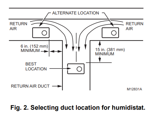
- Select a location for the humidistat on the return plenum or on the wall in the living space.— Mounting on the return plenum is the easiest installation for the control wiring circuit.For return duct mounting, the humidistat should be mounted upstream from the humidifier or bypass so that it is properly sensing the relative humidity of the living space. Locate the control at least 8 in. (203 mm) upstream from the humidifier in the return air duct. (See Fig 2.)
Locating Closest 120V Electrical Outlet
- Select a location with access to an outlet. If not available, contact an electrician to have one installed.
- Make sure that the humidifier cord is adequate to reach from the humidifier to the outlet.
- Make sure that the 20 ft (6.2m) of thermostat wire is adequate to reach from the humidifier solenoid to the sail switch, to the humidistat.
Installing the Humidifier
 WARNINGHazardous VoltageCan cause personal injury or equipment damage.Do not cut or drill into any air conditioning or electrical accessory.
![]() CAUTIONSharp Edges Installation Hazard.Can cause personal injury.Wear gloves and safety glasses.
CAUTIONSharp Edges Installation Hazard.Can cause personal injury.Wear gloves and safety glasses.
- Turn off power to the air handling system at the circuit breaker.
- Draw a level line on the plenum in the location chosen for the humidifier. (Leveling assures optimal humidifier performance.)
- Locate the template (form number 69-1651 included in the box).
- Tape the template in position and trace around the template.
- Remove the template and carefully cut the rectangular opening.
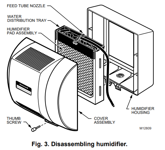
- Disassemble the humidifier; remove the cover and take out the humidifier pad assembly. See Fig. 3.

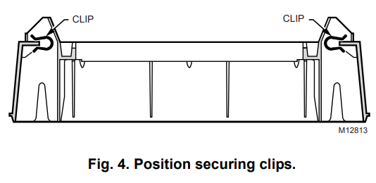
- Position the securing clips as shown in Fig. 4.
- Make sure the humidifier housing is level, then position it in the opening so the plastic tabs are in place on the lower sheet metal edge of the opening. Use pliers, as necessary, to flatten cut edges. See Fig. 5.
- Push in securing clips until completely seated.
- Drill holes and install the three sheet metal screws on the top of the humidifier housing. Secure the housing with the three remaining screws.
- Reinstall the humidifier pad assembly in the humidifier housing.IMPORTANTBe sure to reconnect the water feed tube and ensure that the tube is not pinched or kinked.
- Hinge the cover in place and secure with the thumbscrew located at the bottom of the cover.

Connecting the Plumbing
- Shut off the water. CAUTIONChemical Hazard.Can cause personal injury or equipment damage.Do not use any line connected to an air conditioner.Do not use gas line.
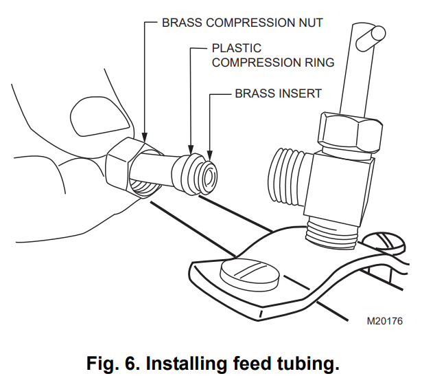
- First, connect 1/4-in. line to the humidifier’s solenoid valve, located at the bottom of the humidifier.a. Remove the compression nut.b. Discard the brass ring, replacing it with the plastic ring.c. Install the brass insert into the end of the tubing.d. Insert the tubing into the solenoid valve fitting and support the valve while tightening the compression nut.NOTE: Do not over-tighten the compression nut. Moderate tightness prevents leaking.
- Use the saddle valve (included) to tap into the water supply line at the location selected. See Fig. 8.If tapping into the galvanized pipe, drain line, and pre-drill 3/17-in. tap for saddle valve.NOTE: The saddle valve is not designed to regulate water flow. The valve is either open or closed.IMPORTANTTo prevent debris from clogging the solenoid inline filter, be sure to install the saddle valve handle pointing toward the ceiling.
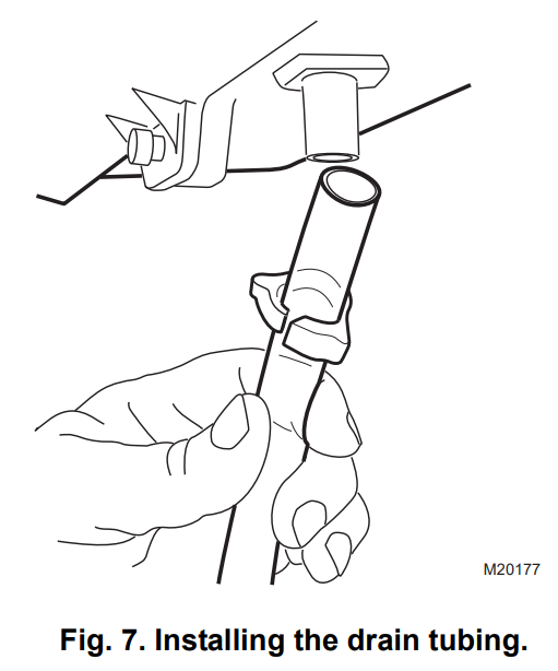
- Use 1/4-in. (6mm) OD tubing and connect the saddle valve to the inlet side of the solenoid valve on the humidifier (See Fig. 9).
- Repeat step 2, a – d for saddle valve fitting.NOTE: Cut tubing to correct length so the tubing terminates at the drain.
Air Pressure Switch Installation
IMPORTANTDo not install the switch in an area where temperature exceeds the rating of -40F to 190F (-40C to 88C)
- Disconnect power from the humidifier before installing.
- Mount the switch vertically with pressure connectors facing down, using provided self-tapping screws to secure the switch to the duct.IMPORTANTCalibration accuracy requires that the switch be mounted vertically (as pictured in Fig. 8).
- The return duct is recommended, however, the switch can also be mounted to the supply duct.Fig. 9. Mounting the pressure switch.SUPPLY DUCT INSTALL – AIRLINE ONLY TO TAP A, CONNECTED TO THE + PORT ON THE AIRFLOW SWITCHRETURN DUCT INSTALL – AIRLINE ONLY TO TAP B, CONNECTED TO THE – PORT ON THE AIRFLOW SWITCHSUPPLY/RETURN DUCT INSTALL – AIRLINE CONNECTED TO BOTH THE + AND – PORTS ON THE AIRFLOW SWITCHM27303
- Cut a 3/4-in. diameter hole in the duct within 10 feet of the switch to ensure the provided tubing reaches the pressure tap elbow.
- Insert the black rubber gasket into the duct hole.
- Connect the tubing to the tubing fitting elbow and insert the tubing fitting elbow into the black rubber gasket.
- Connect the other end of the tubing to the applicable pressure connection on the switch.e. Black connection if installed on the supplyf. Grey connection if installed on the returng. Both grey and black if installed on both
IMPORTANTWith low-speed airflow or variable speed systems it is recommended to run tubing to both the supply and return ducts.
Fig. 10. Install tubing.CONNECT TUBING TO + CONNECTION IF PRESSURE TAP IS MOUNTED TO SUPPLY DUCT. CONNECT TO – IF PRESSURE TAP IS MOUNTED TO RETURN DUCT.M27304 -
You may cut the tubing to fit the connection length between the tubing fitting elbow and switch. It is also recommended to secure the hose to existing structures to avoid accidental disconnection.
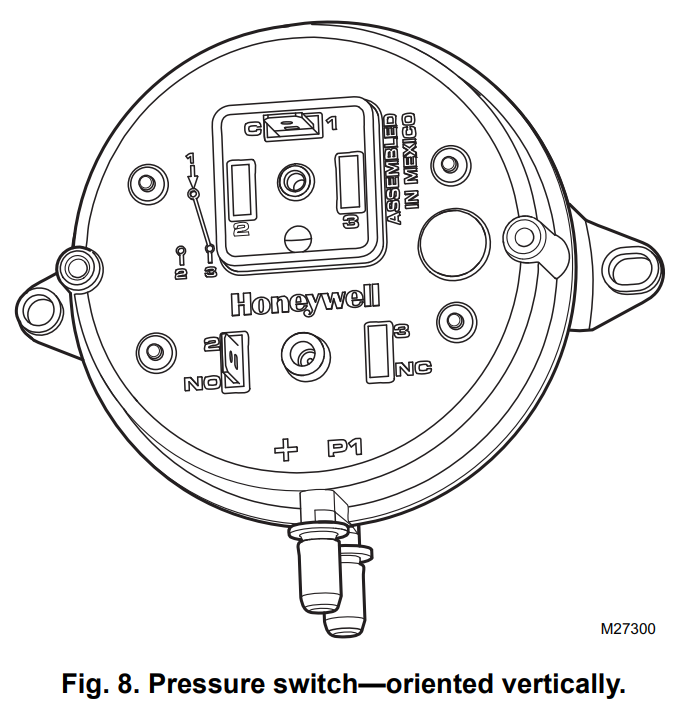
 Fig. 9. Mounting the pressure switch.SUPPLY DUCT INSTALL – AIRLINE ONLY TO TAP A, CONNECTED TO THE + PORT ON THE AIRFLOW SWITCHRETURN DUCT INSTALL – AIRLINE ONLY TO TAP B, CONNECTED TO THE – PORT ON THE AIRFLOW SWITCHSUPPLY/RETURN DUCT INSTALL – AIRLINE CONNECTED TO BOTH THE + AND – PORTS ON THE AIRFLOW SWITCHM27303
 Fig. 10. Install tubing.CONNECT TUBING TO + CONNECTION IF PRESSURE TAP IS MOUNTED TO SUPPLY DUCT. CONNECT TO – IF PRESSURE TAP IS MOUNTED TO RETURN DUCT.M27304
Installing the Humidistat
Installing on Mounting Duct
- Apply the template to the duct location chosen for the humidistat. Make sure the template is level before drilling the holes.
- Refer to the template (provided with the H8908 Humidistat Installation Instructions) to drill the control assembly opening and mounting holes for the H8908.
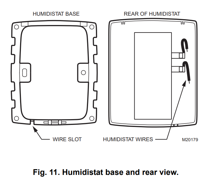
- Remove the H8908 case from the base.
- Position the foam gasket on the H8908 base.
- Position the base on the duct with the arrow up.
- Secure the base to the duct using the four1 in. (25 mm) mounting screws provided with humidistat.
- Connect the low-voltage wires to the leads and replace the H8908 case. See Fig. 12.NOTE: For wall mounting instructions, see the H8908 Installation Instructions.
WIRING
CAUTIONHazardous Voltage.Can cause personal injury or equipment damage.Disconnect power supply before installing or servicing equipment.IMPORTANTAll wiring must comply with applicable local codes, ordinances, and regulations.Wire the humidifier solenoid valve, pressure switch, humidistat, and transformer. See Fig. 13.

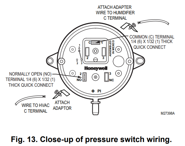
- Run the two-strand thermostat wire from the humidifier to the humidistat, and from the humidistat to the pressure switch and back to complete the wiring loop to the humidifier. This is illustrated in Fig. 12.
- Cut lengths of thermostat wire to reach between components, leaving adequate wire at both ends for connections.NOTE: Humidistat and pressure switch can be wired in any order.
- At the humidifier, connect the black and white conductors to the two yellow humidifier wires. (The red wires from the humidifier are not used.)
- At the humidistat, connect both black conductors to the two humidistat terminals. Use a wire nut to connect together the two white conductors.
TESTING HUMIDIFIER OPERATION
Checklist
- A humidifier is a level.
- Control wiring was reviewed using circuit diagram.
- A humidifier is plugged in.
- Feedline has no kinks.
- The drain line slopes continuously down and ends at the floor drain.
- The water hose inside the humidifier is connected to the PerfectFlow™ water distribution tray.
After installation use the following steps to check the humidifier operation:
- Turn on the power and the water supply
- Turn the H8908 Humidistat to On and turn on the heat by setting the thermostat to 10ºF (6ºC) above room temperature.IMPORTANT The furnace blower must be on to activate the humidifier.
- Make sure that water is flowing out of the drain hose. If water does not flow, see Troubleshooting Your Humidifier section.
- Check for leaks.
- Reset the thermostat and H8908 Humidistat to a comfortable setting for automatic operation.
OPERATION
How Your Humidifier WorksYour Honeywell humidifier uses the principle that vapor (evaporated water) is created when warm air blows over a water-soaked area. As the vapor circulates, the relative humidity rises.Your humidity control monitors the relative humidity and activates the humidifier accordingly. The humidifier has a water supply that dispenses water evenly over a humidifier pad. The warm dry air, from the furnace, passes over the humidifier pad and picks up the moist air to circulate it throughout your home.Humidified air feels warmer and more comfortable so you may be able to lower your thermostat heating setpoint, which saves money on your heating fuel bills. The end result is that your humidifier gives you a comfortable environment that is also energy efficient. Controlling Your Humidity SettingsYour H8908 Humidistat controls your humidifier.
- Choose the humidity control setting using the combination of relative humidity/outdoor temperature setting scale on your humidity control dial.
- Match the dial set to the outdoor temperature to optimize the humidity level while reducing the moisture condensation on your windows. See Table 2 to adjust the humidity control to the recommended setting.NOTE: As the outside temperature drops, a lower humidity setting is recommended to accommodate dewpoint effects.These settings should reduce the accumulation of moisture and ice on windows and other areas of the home.
- Adjust the humidity control setting to adjust for indoor activities such as cooking, showering and clothes drying, which can cause excessive levels of humidity that can accumulate moisture on your windows.NOTE: If these activities persist for more than a few hours, set the humidity control to the lowest setting to turn off the humidifier. If the condition does not improve, ventilate your home to remove the moisture.
Table 2. Setting Your Humidistat.
| When Outside Temperature is: | Use This Control Setting: |
| -20°F (-29°C) | 15 |
| -10°F (-23°C) | 20 |
| 0°F (-18°C) | 25 |
| +10°F (-12°C) | 30 |
| +20°F (-7°C) | 35 |
| Above 20°F (-7°C) | 40 |
MAINTAINING YOUR HUMIDIFIER
A regular maintenance program prolongs the life of your humidifier and makes your home more comfortable. The frequency of cleaning depends on the condition of your water.You can use either hard or soft water in your humidifier, but hard water mineral deposits are more difficult to clean than soft water deposits. Use the following procedure to clean your Honeywell humidifier. WARNINGSerious Personal Injury Hazard.Can cause electrical shock and injury from moving parts.Disconnect power and shut off the water supply before removing the cover.IMPORTANTNever oil any part of the humidifier.
Every 1 to 3 Months (Depending on Water Quality)
- Disconnect the power and turn off the humidifier water supply.
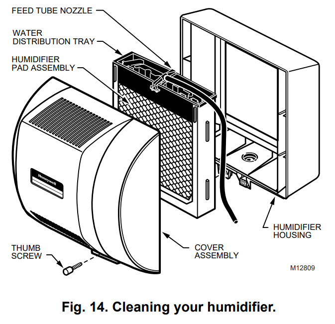
- Remove the humidifier cover by unplugging the connector and loosening the thumbscrew. Grasp the cover near the bottom and pull it toward you. See Fig. 14.
- Remove the humidifier pad assembly from the humidifier by grasping the top of the tray and pulling it toward you.
- Lift the tray off the pad.
- Gently pinch the water nozzle catches inward until you can lift the water nozzle off the tray.
- Carefully remove any mineral deposits from the tray and frame. Be sure the frame drain hole has nothing blocking it.
- Disconnect the drain hose from the drain fitting on the bottom of the humidifier housing.
- Clean the drain fitting, if necessary.
- Bend the drain hose to loosen any mineral deposits.
- Flush the drain hose with pressurized water (a running tap) to clean the house.
- Reattach the drain hose to the drain fitting.
- Snap the water nozzle back on the tray.
- Be sure the marked end of the pad is facing up.Place the tray on the new pad.
- Place the humidifier pad assembly in the humidifier housing. Be sure the water feed tube is placed in the guide slots.
- Replace the humidifier cover.
- Verify the humidifier operation by following the steps in the Checking Your Humidifier for Correct Operation section.
CHECKING YOUR HUMIDIFIER FOR CORRECT OPERATION
After winter startup or servicing, use the following steps to check your humidifier operation:
- Turn on the humidifier power and water supply.
- Turn the humidistat to its highest setting and set the thermostat to 10°F (6°C) above the room temperature.
- Observe that water is flowing out of the drain hose.NOTE: The furnace blower must be running to activate the humidifier.
- Reset the thermostat and humidistat to a comfortable setting for automatic operation.
TROUBLESHOOTING YOUR HUMIDIFIER
Table 3. Troubleshooting Humidifier.
| Problem | What to look for | What to do |
| Water leakage | Leaking joints. | Shut off water. lighten connections. |
| Brass tubing inserts | Verify that brass tubing inserts are used. | |
| Saddle valve is leaking. | Verify rubber pad is installed on the saddle valve. | |
| No water to drain. | Electrical | Verify control circuit wiring. Check all connections. |
| Humidistat | Turn humidistat up and down and listen for contact to click. | |
| Humidifier power | Verify that outlet has power. | |
| Solenoid | After verifying other wiring components, turn on the furnace fan. turn humidistat up and down, and listen for the solenoid to click. | |
| Plumbing | Verify plumbing connections. Check for kinks. | |
| Saddle valve | Verify that the needle pierces water line and then backs out needle to open the valve. | |
| Humidifier | Remove cover and verify that water flows into the distribution tray. | |
| Drain tubing | Verify no obstructions. | |
| Low humidity | The furnace blower not operating. | •Reset the circuit breaker or check for a blown fuse.•Check that the furnace power is on.•Check all external wiring connections.•Check the humidity control setting•Call a professional heating contractor. |
| Rapid air changes. Drafts (cold air is dry and is an added load to the humidifier). | •Keep doors and windows closed.•Close fireplace damper when not in use.•Keep exhaust fan running time to a minimum.•Seal around doors and windows. | |
| High humidity | Condensation on walls. | •Turn off humidity control and water until condensation is completely evaporated. |
| Heavy condensation on windows. | •Turn humidity control down low enough to eliminate condensation caused by moisture from bathing, mopping, cooking. etc. If moisture persists. more ventilation is needed. |
LIMITED ONE-YEAR WARRANTY
Honeywell warrants this product, excluding humidifier pad, to be free from defects in the workmanship or materials, under normal use and service, for a period of one (1) year from the date of purchase by the consumer. If, at any time during the warranty period, the product is defective or malfunctions, Honeywell shall repair or replace it (at Honeywell’s option) within a reasonable period of time.If the product is defective, return it, with a bill of sale or other dated proof of purchase, to the retailer where you purchased it.This warranty does not cover removal or reinstallation costs. This warranty shall not apply if it is shown by Honeywell that the defect or malfunction was caused by damage that occurred while the product was in the possession of a consumer.Honeywell’s sole responsibility shall be to repair or replace the product within the terms stated above. HONEYWELL SHALL NOT BE LIABLE FOR ANY LOSS OR DAMAGE OF ANY KIND, INCLUDING ANY INCIDENTAL OR CONSEQUENTIAL DAMAGES RESULTING, DIRECTLY OR INDIRECTLY, FROM ANY BREACH OF ANY WARRANTY, EXPRESS OR IMPLIED, OR ANY OTHER FAILURE OF THIS PRODUCT. Some states do not allow the exclusion or limitation of incidental or consequential damages, so this limitation may not apply to you.THIS WARRANTY IS THE ONLY EXPRESS WARRANTY HONEYWELL MAKES ON THIS PRODUCT. THE DURATION OF ANY IMPLIED WARRANTIES, INCLUDING THE WARRANTIES OF MERCHANTABILITY AND FITNESS FOR A PARTICULAR PURPOSE, IS HEREBY LIMITED TO THE ONE-YEAR DURATION OF THIS WARRANTY. Some states do not allow limitations on how long an implied warranty lasts, so the above limitation may not apply to you.This warranty gives you specific legal rights, and you may have other rights which vary from state to state.If you have any questions concerning this warranty, please write to Honeywell Customer Care, 1885 Douglas Drive, Minneapolis, MN55422. In Canada, write Retail Products ON15-02H, Honeywell Limited/Honeywell Limitée, 35Dynamic Drive, Scarborough, Ontario M1V 4Z9.
![]()
Automation and Control SolutionsHoneywell International Inc.1985 Douglas Drive NorthGolden Valley, MN 55422Honeywell Limited-Honeywell Limitée35 Dynamic DriveToronto, Ontario M1V 4Z9customer.honeywell.com
® U.S. Registered Trademark© 2010 Honeywell International Inc.69-2517EF—01 M.S. Rev. 11-10Printed in the U.S.A.

References
[xyz-ips snippet=”download-snippet”]