![]()
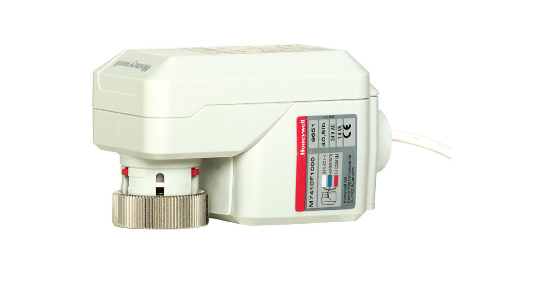
M6410A, M7410F, M6435A, M7435F ActuatorsV5852A, V5853A, V5862A, V5863A Valves40.5 LB (180N) NON-SPRING AND SPRING RETURN ACTUATORSAND 1/2 INCH, 3/4 INCH CARTRIDGE GLOBE VALVES
PRODUCT DATA
APPLICATIONM6410A and M7410F Series 1000 Non-Spring Return Valve Actuators provide floating or modulating control of Series 1000 and 2000 V5852A, V5853A, V5862A and V5863ACartridge Globe Valves.M6435A and M7435F Series 1000 Spring Return Valve Actuators provide floating or modulating control of Series 1000 and 2000 V5852A, V5853A, V5862A and V5863ACartridge Globe Valves.The actuators are used in electronic temperature control systems, which use hot and/or cold water (with glycol up to 50 percent) as the controlled medium in variable air volume (VAV) terminal units, fan-coil units, small reheaters, and coolers.The V5852A, V5853A, V5862A, V5863A Series 1000 and 2000 Cartridge Globe Valves can also be controlled by MP958A Pneumatic Valve Actuators.
FEATURES
- Small size allows installation in limited space.
- Long-stroke allows a wider range of control.
Actuators
- Low power consumption.
- Synchronous motor.
- No mounting tools are required (including the MP958).
- Low-maintenance plastic housing.
- Conduit connector standard.
- No separate linkage is required.
- M64XXA provides 3-position floating control without proportional feedback.
- M74XXF receives 0 to 10 Vdc or 2 to 10 Vdc input signal, selectable at the site.
- M74XXF includes a direct/reverse acting switch.Non-Spring Return (M6410A, M7410F)
- Especially suitable for Excel® Controller or Individual Room Controller (IRC) System.
- Internal valve position indicator.
- Magnetic coupling for torque limitation independent of the voltage supply, and self-adjustment of the close-off port.
- Ready-to-wire connecting cable.Spring Return (M6435A, M7435F)
- Force-limiting end switches.
- No calibration.
Valves
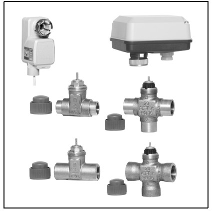
- V5852A is a two-way female sweat valve.
- V5853A is a three-way female sweat mixing valve.
- V5862A is a two-way female NPT valve.
- V5863A is a three-way female NPT mixing valve.
- A soft valve seat provides a low leakage rate.
- Valve inserts are changeable without draining the valve when used with the insert replacement tool.
- The threaded plastic cover allows manual operation.
- Brass body and stainless steel stem.


SPECIFICATIONS
IMPORTANTThe specifications given in this publication do not include normal manufacturing tolerances. Therefore, an individual unit may not exactly match the listed specifications. Also, this product is tested and calibrated under closely controlled conditions and some minor differences in performance can be expected if those conditions are changed.Models:M6410A: Non-Spring Return Valve Actuator. Provides floating control of the V5852A, V5853A, V5862A and V5863A Valves.M6435A: Spring Return Valve Actuator. Provides floating control of V5852A, V5853A, V5862A and V5863A Valves.Stem retracts upon power failure.M7410F: Non-Spring Return Valve Actuator. Provides modulating control of V5852A, V5853A, V5862A and V5863A Valves.M7435F: Spring Return Valve Actuator. Provides modulating control of V5852A, V5853A, V5862A and V5863A Valves.Stem retracts upon power failure.V5852A: Two-way Sweat Valves.V5853A: Three-way Sweat Mixing Valves.V5862A: Two-way NPT Valves.V5863A: Three-way NPT Mixing Valves.
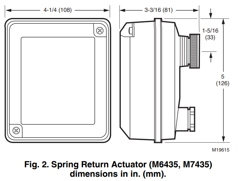
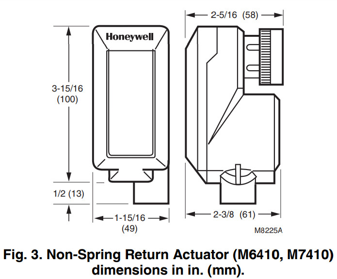
CAUTIONEquipment Damage Hazard.Installing a high-force (67.5 lb [300 N]) actuator on 1/2 or 3/4 in. valve can damage the valve beyond repair.Use only Series 1000 (40.5 lb [180 N]) actuators with these smaller (1/2 in. and 3/4 in.) valves.IMPORTANT— Complete valve body soldering (V5852, V5853) before installing cartridge inserts.— Install low-force actuators (40.5 lb) only on small valves (1/2 in., 3/4 in.).Dimensions:Valves: See Fig. 1.Spring Return Actuators: See Fig. 2.Non-Spring Return Actuators: See Fig. 3.Stroke: 1/4 in. (6.5 mm).
Control Modes:M6410A, M6435A: Floating.M7410F, M7435F: Modulating.Electrical Ratings:Input Power:M6410A, M7410F: 24 Vac, +10/-30 percent, 50/60 Hz.M6435A, M7435F: 24 Vac, +20/-15 percent, 50/60 Hz.Power Consumption:M6410A: 0.7 VA.M7410F: 1.4 VA.M6435A: 10 VA.M7435F: 5 VA.Input Signal (M7410F, M7435F): Modulating 0 to 10V, 2 to 10V (adjustable), 0.1 mA.Input Impedance (M7410F, M7435F): 100K ohms.Ambient Ratings:Operating Temperature Range: 32° to 122°F (0° to 50°C).Storage Temperature Range: -40° to 158°F (-40° to 70°C).Humidity Range: 5 to 95% RH (noncondensing).Mounting: Actuator screws onto valve body.Connections:M6410A, M7410F: 4.9 ft (1.5m) cable.M6435A, M7435F: 1.5 sq mm terminals.Weight:M6410A: 5 oz (0.15 kg).M7410F: 5.6 oz (0.16 kg).M6435A, M7435F: 17.6 oz (0.5 kg).Running Time:At 50 Hz:M6410A, M7410F: 150 seconds.M6435A, M7435F: 60 seconds.At 60 Hz:M6410A, M7410F: 125 seconds.M6435A, M7435F: 50 seconds.Spring Return Time: 10 seconds.Stem Force: 40.5 lb (180 N).Suitable Medium: Water with maximum 50% glycol.Controlled Water Temperature: 36° to 230°F (2° to 110°C).Leakage Rate: <0.02% of Cv.
ORDERING INFORMATION
When purchasing replacement and modernization products from your TRADELINE® wholesaler or distributor, refer to the TRADELINE® Catalog or price sheets for the complete ordering number.If you have additional questions, need further information, or would like to comment on our products or services, please write phone:
- Your local Honeywell Automation and Control Products Sales Office (check white pages of your phone directory).
- Honeywell Customer Care1885 Douglas Drive NorthMinneapolis, Minnesota 55422-4386
International Sales and Service Offices in all principal cities of the world. Manufacturing in Australia, Canada, Finland, France Germany, Japan, Mexico, Netherlands, Spain, Taiwan, United Kingdom, U.S.A.
Actuator Required:M6410A: Non-Spring Return Valve Actuator (3-position floating).M6435A: Spring Return Valve Actuator (3-position floating; stem retracts upon power failure).M7410F: 0 to 10 Vdc or 2 to 10 Vdc Electronic Actuator, orM7435F: Spring Return Valve Actuator (modulating control; stem retracts upon power failure).MP958: Pneumatic Valve Actuator.Valve inserts are provided as spare parts. See Table 2.Rangeability:Two-way Valve: 100:1.Three-way Valve: 50:1 for the controlled port (A to AB).Flow Characteristic:V5853, V5863: A to AB: Equal Percentage.B to AB: Linear.V5852, V5862: Equal percentage.Valve Cv Rating: See Table 1.
NOTE: To determine the capacity index (Cv) needed for your application, use the following formula: Cv = gallons per minute divided by the square root of the pressure drop across the valve when the valve is fully open.Valve Close-off Rating: See Table 1.Body Material:Yellow BrassStem and Plug Assembly:Stem: Stainless steel.Plug: Brass.
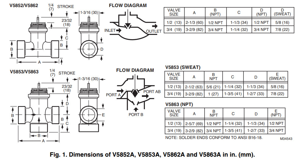
Table 1. Valve Close-off Ratings.
| Pipe Size inin. (mm) | Cva | Close-off Rating (psi) | |
| Two-way | Three-way | ||
| 1/2 (13) | 0.2 | 232 | |
| 0.3 | 232116 | 1 | |
| 0.5 | |||
| 0.7 | 232 | ||
| 1.2 | 174 | ||
| 2.9 | 36174 | ||
| 3/4 (19) | 2.9 | 58 | 34b or 15c |
| 3.6 |
The Cv for the bypass port (B) on all three-way valves is reduced by one Cv level. Example: A Port Cv = 0.5;B Port Cv = 0.3. This feature eliminates the need for a balancing valve with the load matched to the proper Cv.b For V5853A1XXX and V5863A1XXX Valves (Series 1000).c For V5853A2XXX and V5863A2XXX Valves (Series 2000).IMPORTANTMount all valve types in return flow. When delta values exceed 8.70 psi (60 kPa), noise can develop.Approvals (Actuators): Underwriters Laboratories Inc. is listed for plenum use (UL94-5V).Accessories and Replacement Parts:WV108B Brush Tool for valve seat cleaning (used with WV108 tool).WV108M Insert Replacement Tool, for replacing cartridge insert without draining system.
Table 2. Valve Insert Replacement Parts.
| Diameter(in.) | For Valve | Cv | PartNumber | Interchangeable With | ||||
| Two-Way | ||||||||
| 1/2 | V5852A2007, | V5862A2005 | 0.2 | 902812 | 0902809, | 0902810, | 902811 | 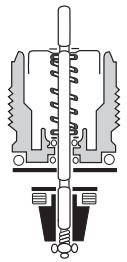 |
| V5852A2015, | V5862A2013 | 0.3 | 902811 | 0902809, | 0902810, | 902812 | ||
| V5852A2023, | V5862A2021 | 0.5 | 902810 | 0902809, | 0902811, | 902812 | ||
| V5852A2031, | V5862A2039 | 0.7 | 902809 | 0902810, | 0902811, | 902812 | ||
| V5852A2049, | V5862A2047 | 1. | 902808 | 902807 | ||||
| V5852A2056, | V5862A2054 | 2. | 902807 | 902808 | ||||
| 3/4 | V5852A2064, | V5862A2062 | 3. | 902814 | 902815 | |||
| V5852A2072, | V5862A2070 | 5. | 902815 | 902814 | ||||
| Three-Way | ||||||||
| 1/2 | V5853A2006, | V5863A2004 | 0.3 | 902821 | 0902822, | 0902823, | 902824 | 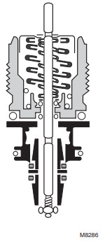 |
| V5853A2014, | V5863A2012 | 0.5 | 902822 | 0902821, | 0902823, | 902824 | ||
| V5853A2022, | V5863A2020 | 0.7 | 902823 | 0902821, | 0902822, | 902823 | ||
| V5853A2030, | V5863A2038 | 1. | 902824 | 0902821, | 0902822, | 902824 | ||
| V5853A2048, | V5863A2046 | 2. | 902825 | None | ||||
| 3/4 | V5853A2055,V5863A1006, | V5853A1008, V5863A2053 | 3. | 902827 | None | |||
| V5853A2063,V5863A1014, | V5853A1016, V5863A2061 | 5. | 902827 | None |
INSTALLATIONWhen Installing this Product…
- Read these instructions carefully. Failure to follow them could damage the product or cause a hazardous condition.
- Check ratings given in instructions and on the product to ensure the product is suitable for your application.
- Installer must be a trained, experienced service technician.
- After installation is complete, check out product operation as provided in these instructions.
 WARNINGSevere Scalding Hazard.Contact with hot liquid can lead to severe injury or cause death.For a pressurized valve, only open with Valve Cartridge Replacement Tool. For complete safety, release system pressure to the valve body before changing cartridge.
 CAUTIONElectrical Shock or Equipment Damage Hazard.Can shock individuals or short equipment circuitry.Disconnect power supply before installation. CAUTIONSweat Valve Damage Hazard.Soldering the valve with the cartridge in place can damage the device.Prior to attaching the valve to piping, remove cartridge from potential exposure to heat.
IMPORTANT
- Before installing the valve and actuator, use the protective cover/manual handle to ensure the valve stem operates freely. An impaired stem operation can indicate a bent stem (due to rough handling). This condition can require replacing the valve.
- When installing valves, make sure the flow direction is correct by checking the arrow on the valve body.
- Mount the valve only with the stem pointing upward.
- Leave the protective cover in place until ready to attach the actuator.
LocationSelect a location where the valve and actuator are accessibleIMPORTANTMount all valve types in return flow. When delta values exceed 8.70 psi (60 kPa), noise can develop.MountingValveThe valve body should be completely installed in the pipe linebefore the actuator is installed.IMPORTANTThe insert is packed separately from the V5852, V5853 Sweat Valve. The valve must be installed and soldered before the insert is installed in the valve.Torque the insert between 27 and 44 in.-lb.
- Verify pipe size and flow direction for the valve being used.
- Position the valve so that the actuator can be easily installed.
- Install the valve using the applicable tools and supplies (wrenches, solder, flux, torch or soldering iron). Follow standard practices.
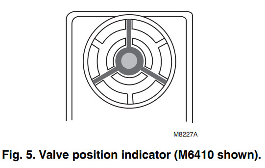
ActuatorNo tools are required to install the M6410A or M7410F on a valve because they are threaded onto the valve by hand. Do not overtighten by using a wrench on the connection, because this can damage the valve or actuator.To mount the M6410A or M7410F Actuator, refer to Fig. 4 through 6. Fig. 5 shows the valve position indicator.
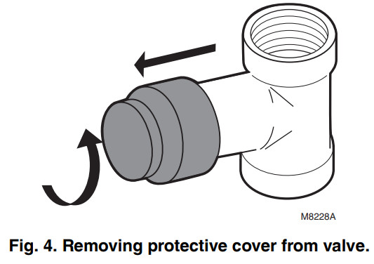
- Remove the protective cover from the valve (Fig. 4).
- Make sure the actuator is in the (factory-supplied) OPEN position.
- Screw the actuator connector onto the body of the valve (Fig. 6).

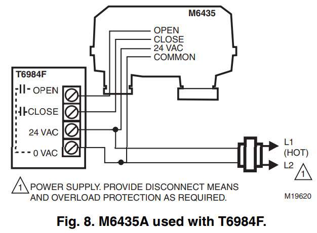
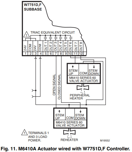
WiringConnect the M6410A, M6435A Actuators to the controller using the controller wiring diagram. See Fig. 8 for a typical T6984F hookup. For Excel, 10 A hookups see Fig. 11.
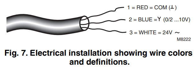
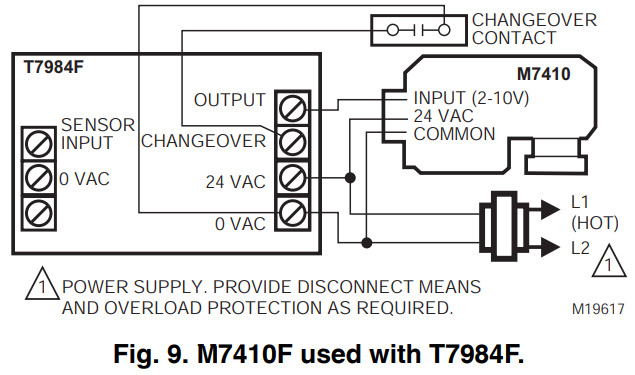
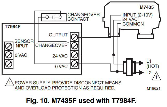
Use the M7410F, M7435F with Excel ® 5000/500/100/80 or T7984 Controllers. Power the M7410F from the same transformer as the controller. See Fig. 9 and 10. Electricalinstallation must comply with the wiring diagram shown in Fig. 7.
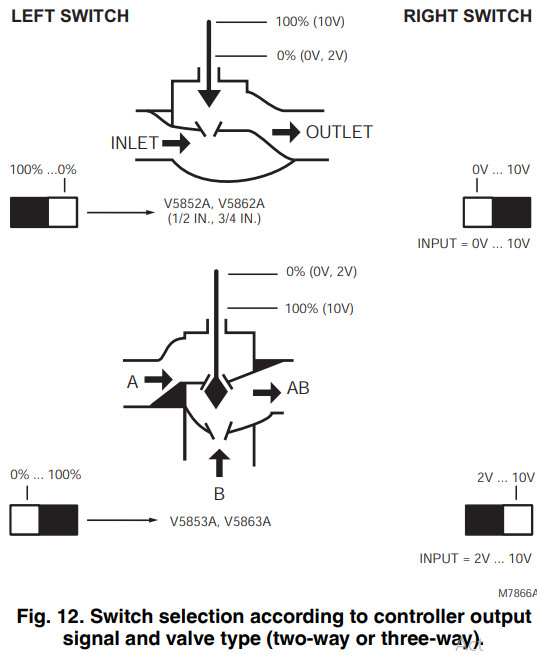
Switch Selection (M7410F)The two built-in selector switches must be set according to the valve type (two-way or three-way) and the controller output signal (0 to 10V or 2 to 10V). See Fig. 12.
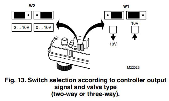
Switch Selection (M7435F)The two built-in selector switches must be set according to the desired valve action and the controller output signal (0 to 10V or 2 to 10V). See Fig. 13.
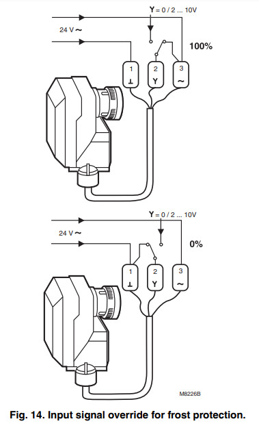
Input Signal Override (M7410F)To override the controller output signal, connect the input signal wire with COM (0%) or 24V (100%), see Fig. 14, using an external relay.If the temperature falls below a certain point; for example, 32°F (0°C), a relay can switch the 24 Vac to the Y connection (0 to 10V, 2 to 10V). This opens or closes the valve.OPERATIONApply power to the actuator to drive the synchronous motor to turn a screw spindle that opens or closes the valve. The actuator is attached to the valve by a hand-tightened coupling ring and a magnetic coupling that limit the gear assembly torque and the actuator driving force.The actuator pushes the center stem of the valve down, compressing the valve spring and closing the valve. When the actuator reverses, the valve spring expands, opening the valve and pushing the center stem up.The valves are supplied with a threaded plastic protective cover/manual handle to protect the stem and to allow for manual operation. Use the protective cover/manual handle to fill the system during initial installation.Turning the protective cover/manual handle:— Clockwise: pushes the center stem of the valve down, compressing the valve spring and closing the valve.— Counterclockwise: allows the spring to expand, pushing the center stem up and opening the valve.
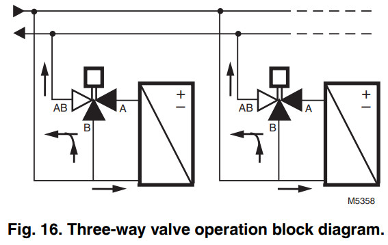
NOTES:— You can also use the protective cover/handle for heating/cooling with neither a controller nor actuator during the building construction phase.— Retain the protective cover. It can be needed for future manual operation.CommissioningA microprocessor within the actuator maintains accurate control/positioning by recommissioning itself every 24 hours or whenever power is applied or interrupted. When power is applied, the actuator drives to 0 and then to its starting position according to the starting/input signal. The initial commissioning or 24-hour recommissioning takes between 2.5 and 5 minutes, depending on the position of the actuator.Valve FlowTWO-WAY VALVESIn the two-way valves, the direction of flow is always from the inlet port to the outlet port as indicated by the arrows on the valve body (see Fig. 15).THREE-WAY VALVESThree-way valves are designed to be used as mixing valves.This means that port AB is the total flow outlet; port A is the controlled flow inlet, and port B is the bypass inlet (see Fig. 16).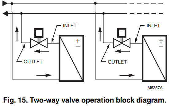
CHECKOUTIMPORTANTOperating the system through one complete cycle is recommended to verify that the valve and actuator function properly.ValveCheck Body and Connections for LeaksBefore installing the actuator, make sure that the valve stem operates freely by using the protective cover/manual handle.Impaired stem operation can indicate that the body was twisted by faulty piping or that the stem was bent by rough handling. Either of these conditions can require the replacement of the valve or cartridge insert.If leaking or other problems occur:
- Remove pressure from the valve.
- Remove the cartridge insert.NOTE: Instructions for removing and replacing the cartridge insert are packed with the WV108Insert Replacement Tool.
- Make sure the cartridge insert O-ring is properly seated and not damaged.
- After installing the actuator, check the actuator’s operation.
ActuatorPerform a functional checkout of the M6410A Actuator as follows:
- Change the room temperature setpoint by at least 10°F (6°C).
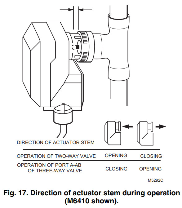
- Make sure the actuator either opens or closes the valve, depending on the direction of the temperature change. See Fig. 17.
- If the actuator stem moves in the wrong direction, reverse the connections for the open and close actuator wires.
- If step 3 does not resolve the problem, replace the actuator.
Perform a functional checkout of the M7410F Actuator as follows:
- Change the Y input signal. The movement of the actuator stem (Fig. 17) indicates if the valve is opening or closing.
- If the direction of the valve stem travel is not correct, reset the direct/reverse switch.
By using this Honeywell literature, you agree that Honeywell will have no liability for any damages arising out of your use or modification to, the literature. You will defend and indemnify Honeywell, its affiliates and subsidiaries, from and against any liability, cost, or damages,including attorneys’ fees, arising out of, or resulting from, any modification to the literature by you.
Automation and Control SolutionsHoneywell International Inc.1985 Douglas Drive NorthGolden Valley, MN 55422customer.honeywell.com
® U.S. Registered Trademark© 2013 Honeywell International Inc.62-0100—11 M.S. Rev. 04-13Printed in United States
![]()
[xyz-ips snippet=”download-snippet”]