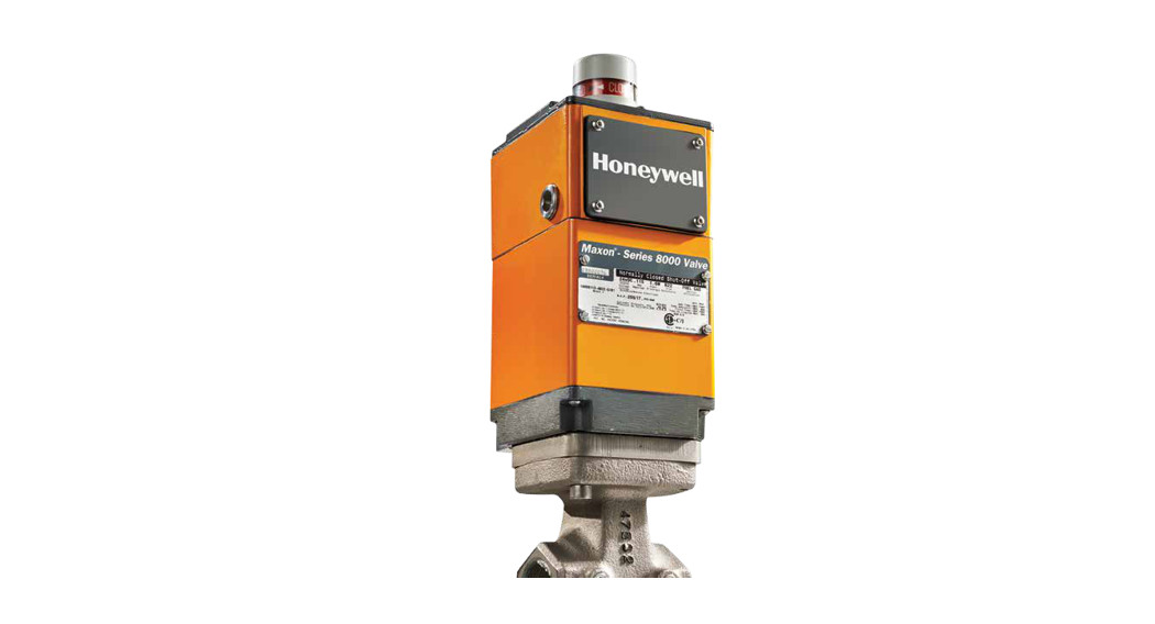
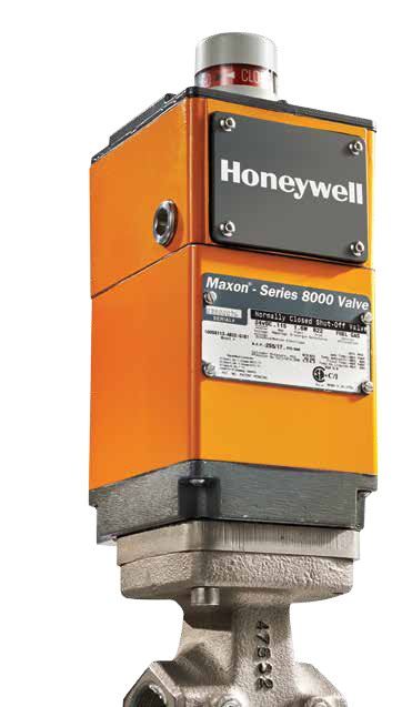
 MAXON PSCHECK™ Partial Stroke Technology with Series 8000 Pneumatic Safety Shut-off Valve
Selection Guide

Safety First.Efficiency First.Success First.
 |
 |
Choose the configuration that’s right for your system.
| Features | Panel Options | ||
| LED Indicator Lights
No display has buttons and indicator lights |
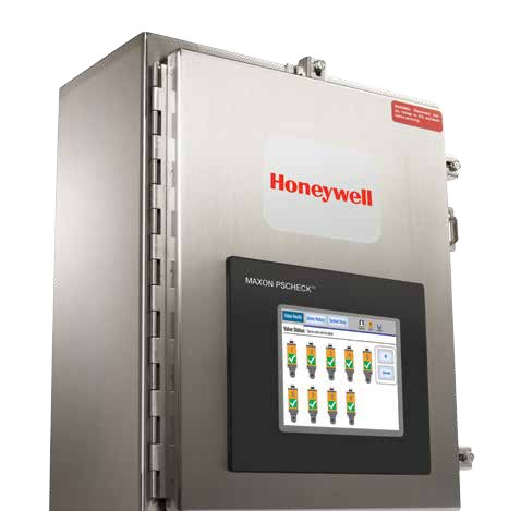
LCD Touchscreen Display
Display only, easy-to-use interface |
DCS IntegrationThe plain panel connects through the system | |
| CONFIGURATION | 1-5 Valve Systems | 1-9 Valve Systems | 1-9 Valves Systems |
| Z Partial Stroke Test verification of test pass/fail | • | • | • |
| Data logging | • | ||
| Valve degradation error detection | • | • | |
| Export of valve trending information | • | ||
| RATING | SIL 2 | Optional | Optional |
| Class I Division 1 (Z-Purge via pressurized panel) | Special Order | Special Order | |
| Class I Division 2 | Optional | Optional | |
| General-purpose Type 12 enclosure | Optional | Optional | Optional |
| Type 4x enclosure | Optional | Optional | Optional |
| SOFTWARE | Date valve built (manufacturer setting) | Factory set | Factory set |
| Date valve is installed and commissioned | Factory set | • | |
| Valve identification/location | • | ||
| Trending of valve performance | • | ||
| Compare valve historical trending data | • | ||
| View alarm history | • | ||
| Manual test | Keyed access | • | • |
| Automatically run partial stroke tests | • | • | • |
| Set frequency of test | Factory set | • | |
| Set limits on hard and soft alarms | • | ||
| SPECIALS | User authorization | Keyed access | • |
| Panel heater | Special Order | Special Order | Special Order |
| Panel cooler | Special Order | Special Order | Special Order |
| HARDWARE PANEL ADD-ON | Pressure transducer – air line pressure measurement | Special Order | Special Order |
| Inlet panel voltage options: | 24VDC,110-240VACor24VAC | 24VDC,110-240VACor24VAC | 24VDC,110-240VACor24VAC |
| Communications options –•Ethernet • Modlous 1761-NET• Modbus AIC+•Non-safety communications | • | • |
Panel Sizes
Non-SIL, Type 12, Type 4X panel sizes:
| 1-2 Valve Systems | 20″H x 20″W x 8″D |
| 3-5 Valve Systems | 24″H x 24″W x 8″D |
| 6-9 Valve Systems | 36″H x 30″W x 10″D |
SIL, Type 4X panel size:
| 1-9 Valve Systems | 36″H x 36″W x 12″D |

Explanation of features
CONFIGURATIONPartial Stroke Test verification of test pass/fail – The partial stroke test can be run manually or automatically at pre-set times. Depending on the system capabilities, the valve’s health status will be conveyed either by LED indicator lights on the panel, via an icon on the touch screen display or via direct communication to the DCS.Data logging – Valve health trending data is captured in non-volatile microprocessor memory and will retain all of the valve health information for up to 10 years or longerdependent on how many times a year the valve partial stroke test is run.Valve degradation error detection – Tests performed by MAXON PSCHECK systems will identify a soft or hard failure (on the 8000 pneumatic SSOV) by checking the amount of time required for the valve to ‘trip’, signaling a capability to either open or close. The longer time it takes to trip the valve indicates potential performance issues. If the valve is degrading it will signal a soft failure alert, if the valve fails it will indicate a failure.Export of valve trending information – It is simple to export the valve health trending data via a supplied Compact Flash (CF) drive. The information is presented in a . CSV format that can be modified for analysis, audits, and for presentation to regulatory or insurance authorities.SOFTWAREDate valve built – A factory build date will be established in permanent memory. Date valve installed and commissioned – During the commissioning process, the customer will be required to set the date the system is installed which will also establish the baseline for the valve’s health.Valve identification/location – The customer has the ability to set a custom number for each valve to help identify its location.Trending of valve performance – Diagnostics captures the valve testing information and tracks the overall health of the 8000 pneumatic safety shut-off valve by plotting this information on a touch screen display showing the valve’s health trending over the life of the valve. This trending information or predictive indicator shows a linear relationship between the initial installation health data vs. the degradation of the valve’s performance over the life of the valve. This trending data is used to indicate when the valve may require maintenance, replacement or that it will potentially fail.
Compare valve historical trending data – Ability to switch between three different screens changing the number of captured data points enabling better short and longterm viewing of the trending information.View alarm history – Captures all alarms, the dates of the alarms, and valve testing information when either a soft ‘alert’ alarm or a hard ‘failure’ alarm is triggered. The system will track all alarm instances over the life of the valve.Manual test – Ability to start an immediate manual test on the valves by pushing a button on the panel, an icon on the touch screen display or initiated via the DCS dependent on the configuration ordered. The test will return immediate results on the valve’s performance and will not interfere with any pre-set automatic tests nor will it interfere with any of the valve or burner management functions.Automatic test – The unit will ship from the factory with all systems pre-set to a monthly partial stroke test schedule. In systems with the touch screen display or via DCS connection, the customer will have the option to change the frequency of the test timing to daily, weekly, monthly, quarterly, bi-annually, annually or a custom set test rate.Set limits on hard and soft alarms – The unit will ship with factory-set limits on when a hard or soft alarm will trigger indicating that the valve’s performance is degrading and maintenance should be scheduled or that the valve has failed the test. Both can be changed by the customer during the commissioning process or at a later date. These limits can be increased meaning the valve will run longer without any warnings or alerts or can be lowered meaning the system will alarm out, indicating the valve’s degradation sooner.User authorization – For systems with a touch screen display, enables password protected access to limit who can modify the settings and to limit general access to the trending and tracking information. For manual units with LED indicator lights, a key is provided to conduct a manual test.
The MAXON PSCHECK technology is an IEC 61511 SIL2 certified diagnostic system that along with Maxon’s Series 8000 valves helps meet SIL3 compliant Safety Instrumented System (SIS) performance requirements.
Commercial & Industrial Combustion (C&IC)Honeywell
| MUNCIE, INDIANA, USAMaxon201 East 18th StreetP.O. Box 2068Muncie, IN 47307-0068Tel: 765.284.3304Fax: 765.286.8394 | GOLDEN VALLEY, MINNESOTA, USAHoneywell Automation and Control Solutions1985 Douglas Drive NorthGolden Valley, MN 55422-3992www.honeywell.com |
 Follow us on Twitter: @honeywellcpro
![]() Sales Offices & Representatives Worldwidewww.maxoncorp.comcustomer.honeywell.com
Sales Offices & Representatives Worldwidewww.maxoncorp.comcustomer.honeywell.com
 02-00019 PRJuly 2014© 2014 Honeywell International Inc.
[xyz-ips snippet=”download-snippet”]