
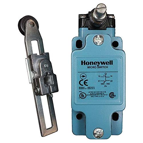
Honeywell Micro Global Limit Switch GLS
WARNING:
- Consult with local safety agencies and their requirements when designing a machine-control link, interface, and all control elements that affect safety.
- Strictly adhere to all installation instructions.
- Failure to comply with these instructions could result in death or serious injury.
- Ensure switch actuator achieves sufficient travel for positive opening of normally closed (NC) contacts to occur.
- Failure to comply with these instructions could result in death or serious injury.
- Refer to:• Page 5 for adjustments.• Pages 9 to 18 for specific travel distances for each switch code, and specifications.• Page 5 proper application of limit switches, and switch mounting dimensions.
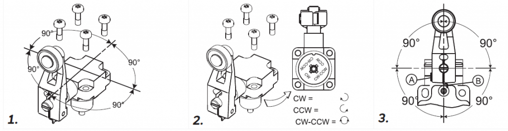
- Perform adjustments (if desired):• Head orientation, page 5.• Actuation direction (Figure 2, page 5).• Side rotary switches with 90* positive drive levers(catalog listings ending in A1A, A1B, A5A, A5B) (Figure 3):– Ensure flats of switch shaft engage groove in actuator lever.– Tighten locking screw (A) until tab (B) no longer moves.
- Mount switch using four M5 or #10 screws. Torque screws to 4,9 Nm to 5,9 Nm [43 in-lb to 52 in-lb].
- Remove screws on cover plate.
- Connect stranded wire (0,75 mm2 to 2,5 mm2, 18-14 AWG) or solid wire (0,75 mm2 to 1,5 mm2, 18-16 AWG) to connector terminals (use 90 *C wire when ambient temperature is over 75 *C). Torque switch terminal screws to 0,8 Nm to 1,0 Nm [7 in-lb to 9 in-lb]. Wire strip length should be 7,3 mm [0.29 in] max.
- Seal conduit opening according to instructions in PK 80112.
- Reassemble cover plate, and torque cover screws to 0,5 Nm [4.4 in-lb].
FIELD ADJUSTABLE HEAD
OPERATION REQUIREMENTS
TERMS
- Contact Closed
- Contact Open
- Differential Travel
- Free Position
- Operating Position 1
- Positive Opening 1 to IEC 947-5-1
- Differential Travel 1
- Over Travel
- Maximum Operating Force
- Maximum Disconnect Force
READING OPERATING SPECIFICATIONS

PRODUCT
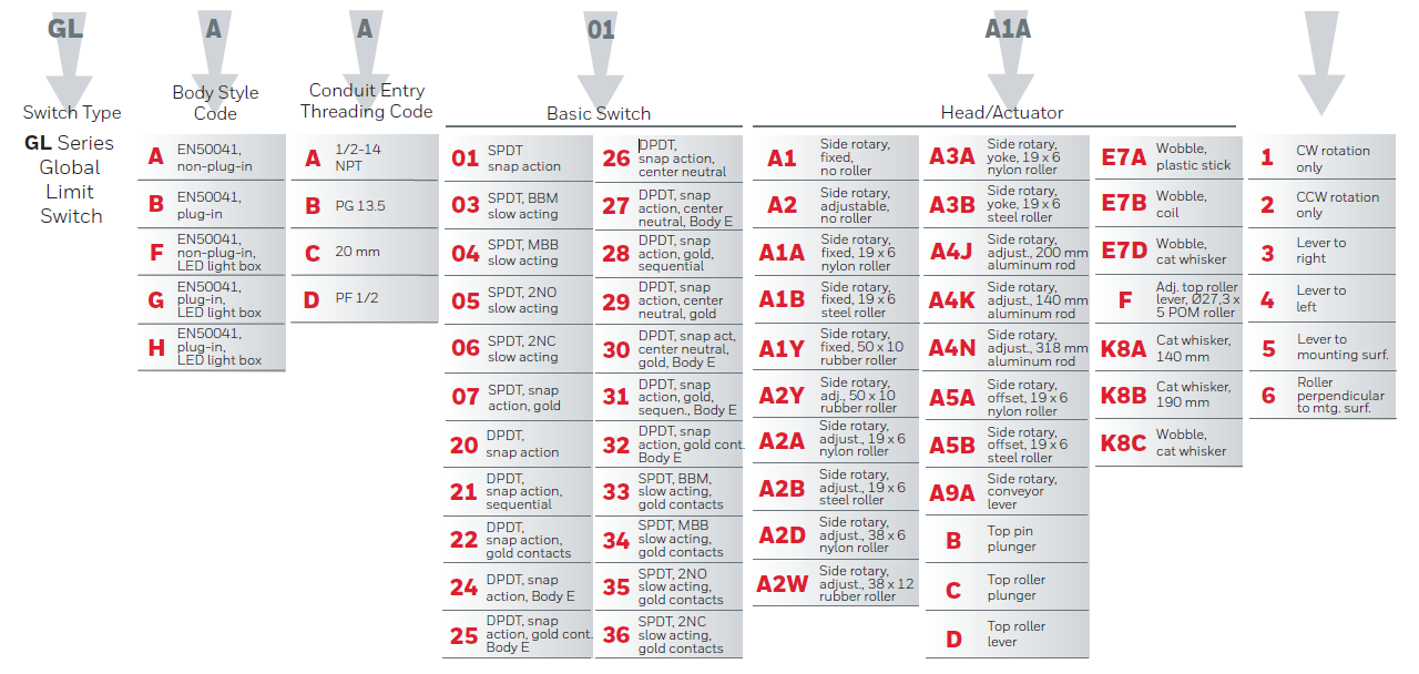
Figure 2. Fixed Lever, Side Rotary Switch – Non-plug-in Body Style, GLZ51 lever, and GLA body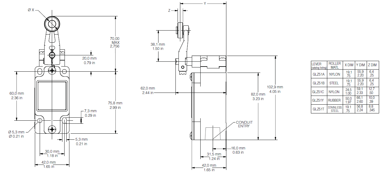
Figure 3. Fixed Lever, Side Rotary Switch – Plug-in Body Style, GLZ51 lever, and GLB body
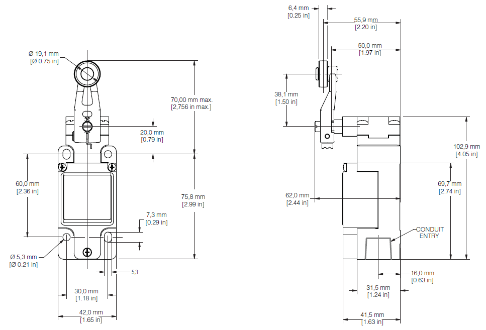
Figure 4. Adjustable Lever Dimensions, GLZ52
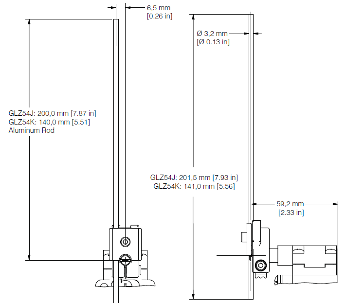
Figure 5. Aluminum Rod Lever Dimensions, GLZ54
Notes:
- Free position, operate point, over travel and pre-travel all to EN 50041
- Operating characteristics apply to counter clockwise (CCW) and clock wise (CW) actuation
- Refer to page 5 for instructions on how to read operating characteristics and specifications
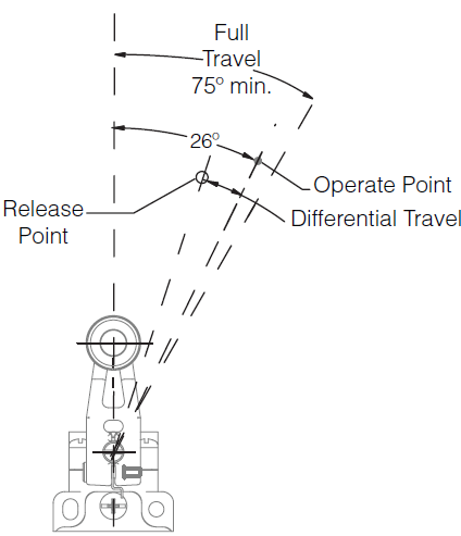
FIGURE 6. HEAD CODE: A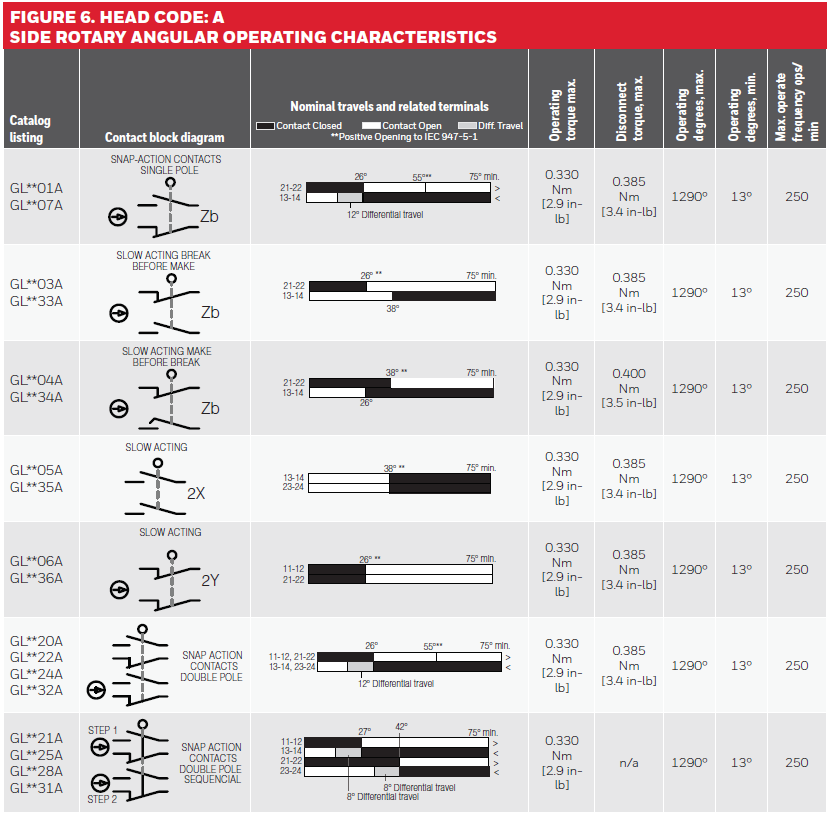
Notes:
- Cam travel for adjustable lever applies when lever is adjusted to 38,1 mm [1.5 in]
- Refer to page 5 for instructions on how to read operating characteristics and specifications

FIGURE 7. HEAD CODE: A • SIDE ROTARY CAM ACTUATION PER EN50041 OPERATING CHARACTERISTICS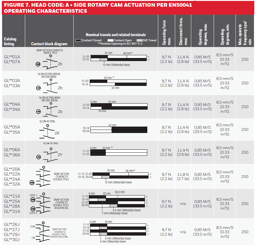
Notes:
- Free position, operate point, overtravel, and pretravel all to EN50041
- Refer to page 5 for instructions on how to read operating characteristics and specifications
FIGURE 8. HEAD CODE: BPIN PLUNGER OPERATING CHARACTERISTICS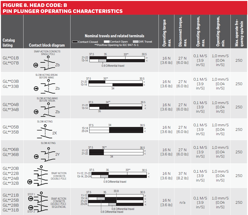
Notes:
- Free position, operate point, overtravel, and pretravel all to EN50041
- Refer to page 5 for instructions on how to read operating characteristics and specifications

FIGURE 9. HEAD CODE: CTOP ROLLER PLUNGER PIN ACTUATION OPERATING CHARACTERISTICS
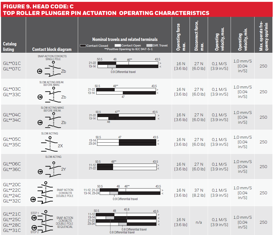
Notes:
- Free position, operate point, overtravel, and pretravel all to EN50041
- Refer to page 5 for instructions on how to read operating characteristics and specifications
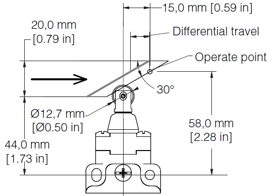
FIGURE 10. HEAD CODE: CROLLER PLUNGER CAM ACTUATION PER EN50041 OPERATING CHARACTERISTICS

Notes:
- Free position, operate point, overtravel, and pretravel all to EN50041
- Refer to page 5 for instructions on how to read operating characteristics and specifications
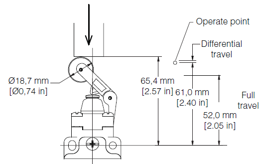
FIGURE 11. HEAD CODE: DTOP ROLLER LEVER PIN ACTUATION OPERATING CHARACTERISTICS
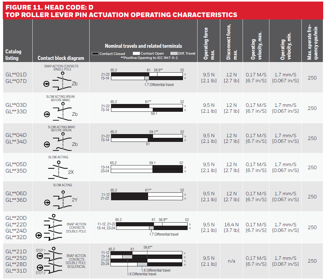
Notes:
- Free position, operate point, overtravel, and pretravel all to EN50041
- Refer to page 5 for instructions on how to read operating characteristics and specifications
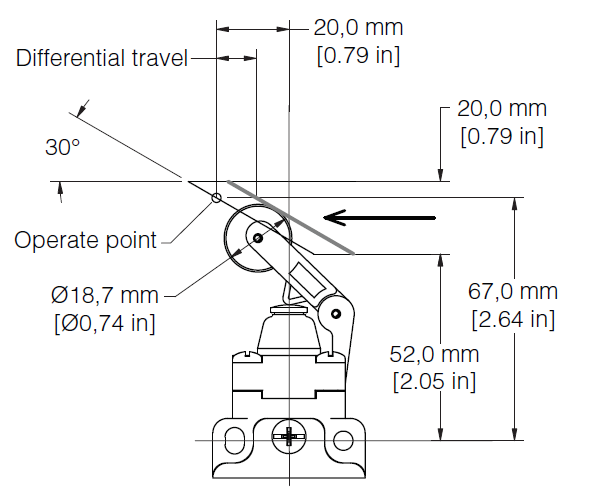
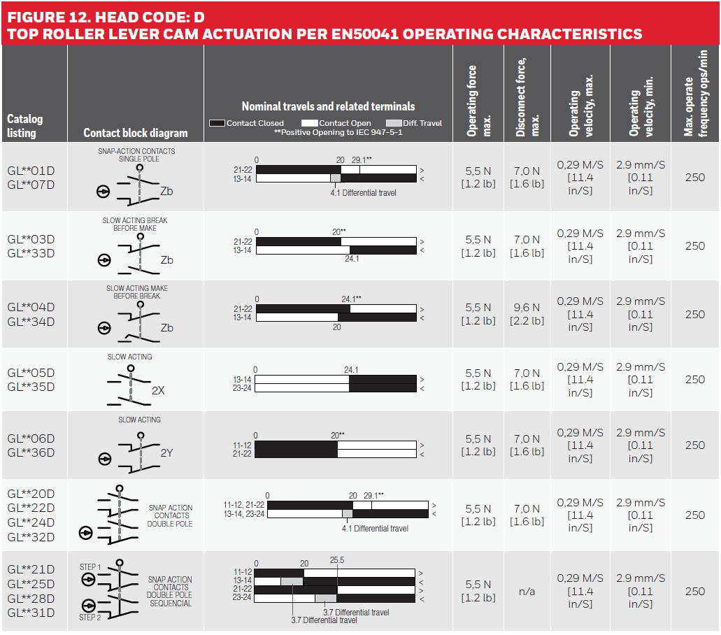
FIGURE 12. HEAD CODE: DTOP ROLLER LEVER CAM ACTUATION PER EN50041 OPERATING CHARACTERISTICS
Head Code: E • WOBBLE AND CAT WHISKER ACTUATOR DIMENSIONS
Figure 13. Coil Actuator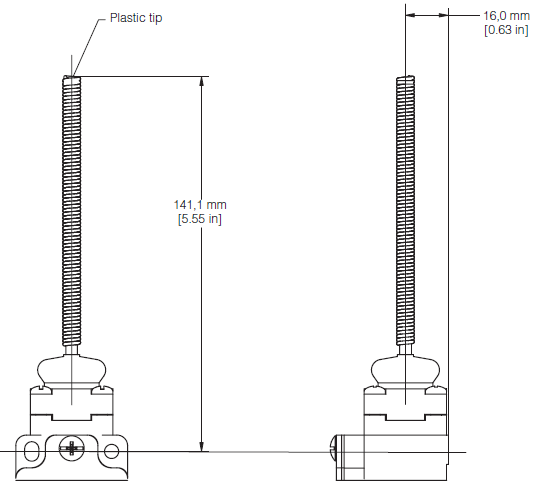
Figure 14. Plastic Rod and Flexible Cable

Figure 15. Cat Whisker Wobbles

Notes:
- Free position, operate point, overtravel, and pretravel all to EN50041
- Refer to page 5 for instructions on how to read operating characteristics and specifications

FIGURE 16. HEAD CODE: EWOBBLE STICK ANGULAR ACTUATION OPERATING CHARACTERISTICS
Notes:
- Free position, operate point, overtravel, and pretravel all to EN50041
- Refer to page 5 for instructions on how to read operating characteristics and specifications
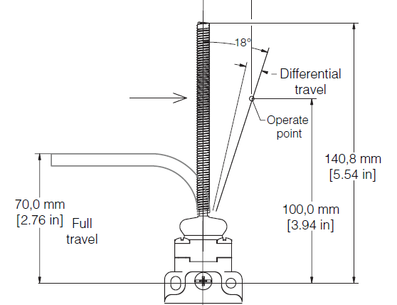
FIGURE 17. HEAD CODE: KWOBBLE STICK ANGULAR ACTUATION OPERATING CHARACTERISTICS

WARRANTY
Honeywell warrants goods of its manufacture as being free of defective materials and faulty workmanship. Honeywell’s standard product warranty applies unless agreed to otherwise by Honeywell in writing; please refer to your order acknowledgement or consult your local sales office for specific warranty details. If warranted goods are returned to Honey-well during the period of coverage, Honeywell will repair or replace, at its option, without charge those items it finds defective. The foregoing is buyer’s sole remedy and is in lieu of all other warranties, expressed or implied, including those of merchantability and fitness for a particular purpose. In no event shall Honeywell be liable for consequential, special, or indirect damages.
While Honeywell may provide application assistance personally, through our literature and the Honeywell web site, it is up to the customer to determine the suitability of the product in the application.Specifications may change without notice. The information we supply is believed to be accurate and reliable as of this printing. However, we assume no responsibility for its use.
FOR MORE INFORMATIONHoneywell Advanced Sensing Technologies services its customers through a worldwide network of sales offices and distributors. For application assistance, current specifications, pricing or the nearest Authorized Distributor, visit our website or call:USA/Canada +1 302 613 4491
USA/Canada +1 302 613 4491Latin America +1 305 805 8188Europe +44 1344 238258Japan +81 (0) 3-6730-7152Singapore +65 6355 2828Greater China +86 4006396841
![]()
HoneywellAdvanced Sensing Technologies 830 East Arapaho Road Richardson, TX 75081sps.honeywell.com/ast
References
[xyz-ips snippet=”download-snippet”]