Honeywell MIDAS-T-NP1 MDA Scientific Midas Gas Detector Pyrolyzer Module Option
Introduction
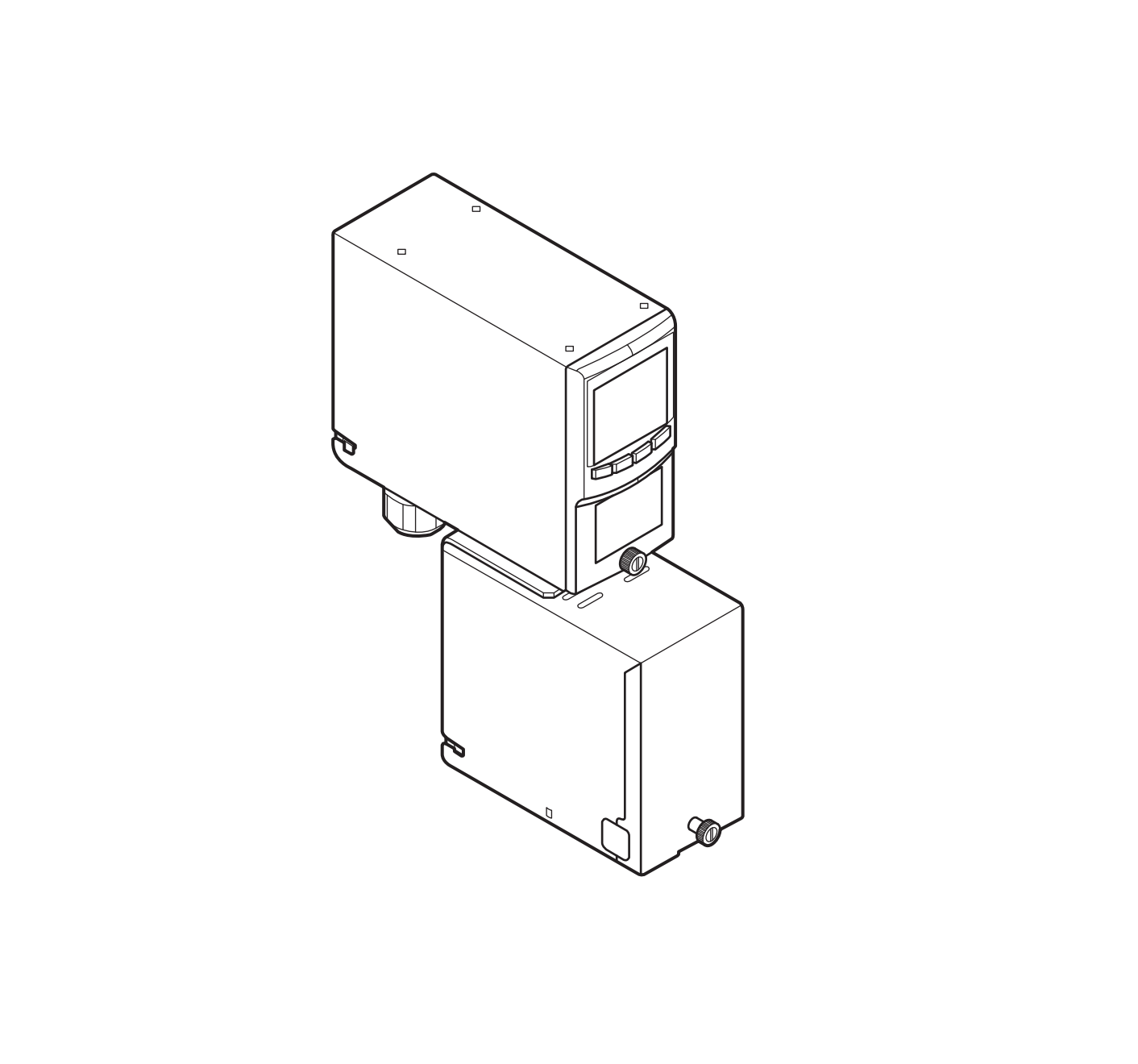
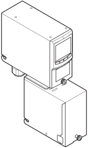
The MIDAS-T-NP1 pyrolyzer option is installed under the standard Midas gas detector. The air sample is drawn through the pyrolyzer to the sensor cartridge. The pyrolyzer converts the target gas present in the air sample into hydrogen fluoride (HF) by means of pyrolysis. The HF can then be measured by the sensor and the concentration displayed as the equivalent reading in ppm of the target gas.
To maintain sensor accuracy when using the pyrolyzer, it is recommended to perform gas calibration every 6 months, and do not allow the ambient temperature at the point of installation to exceed 10-40°C (50104°F) Operation above this temperature may require more frequent bump testing or calibration to confirm working specification. Because of the higher operating temperatures when using the pyrolyzer module, Honeywell Analytics strongly recommends that the ventilated Midas Top Cover (part number MIDAS-A-039) be used in all pyrolyzer applications.
Note: The Pyrolyzer module is serviceable only by trained personnel or by Honeywell Analytics’ Service Center. Inappropriate handling can cause injury and device damage.
Gases that can be detected by the pyrolyzer are shown in this table.
|
Detectable Gases |
||
|
Cartridge Part No. |
Gas |
Gas ID |
|
MIDAS-E-XHF, MIDAS-S-XHF |
NF3 | 01 |
| CH3F |
02 |
|
|
MIDAS-E-XCF, MIDAS-S-XCF |
C4F6 |
01 |
|
C5F8 |
02 |
|
| CH2F2 |
03 |
The unit’s dimensions are shown in Figure 1.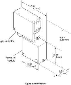
Fitting the Pyrolyzer Module
- Disconnect power to the detector.
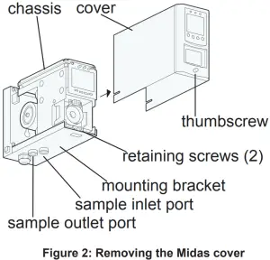
- Unscrew the thumbscrew on the front panel.
- Remove the cover by pulling it forward off the chassis (See Figure 2).

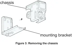
- Unscrew the two retaining screws located at the bottom front of the chassis.
- Pull the chassis forward to disconnect it from the mounting bracket assembly (see Figure 3).
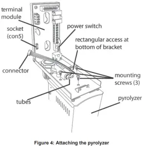
- Thread the connector and wire harness from the pyrolyzer through the rectangular access in the bottom of the mounting bracket.
- Secure the wires with a retention clip (if available).
- Plug the connector into the socket (con5) at the bottom left of the terminal board.
- Align the fitting at the top rear of the pyrolyzer with the sample inlet and outlet ports at the bottom of the mounting bracket.
- Connect the pyrolyzer to the detector with the three provided mounting screws (see Figure 4).
- The flow rate must be calibrated after installing or servicing the pyrolyzer. Refer to the Midas Technical Manual for the calibration procedure.
Reassembling the Detector
- Align:a. the PCB at the top rear of the chassis with the PCB connector at the top of the mounting bracket andb. the two tubes at the bottom rear of the chassis with the two tubes on the bottom of the mounting bracket.
- Slide the chassis backward on the mounting bracket assembly so that the PCB, connector, and tubes engage fully. Push the chassis backward on the mounting bracket. CAUTION: The LCD is fragile. Do not apply pressure to its surface.
- Tighten the retaining screws to secure the chassis to the mounting bracket.
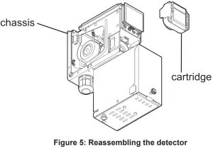
- Insert the sensor cartridge (see Figure 1) into the sensor cartridge chamber (Figure 5) and refer to the Sensor Cartridge Installation Quick Start Guide (MIDAS-A-021).
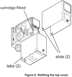
- Set the power switch to the “on” position. 6. Refit the ventilated top by aligning the slots on either side with the locating tabs on the mounting bracket assembly and pushing the cover horizontally until seated.
- Refit the ventilated top by aligning the slots on either side with the locating tabs on the mounting bracket assembly and pushing the cover horizontally until seated.
- Tighten the thumbscrew on the front panel.
Configuring the Detector
- After completion of the startup sequence, press the “” button for a few seconds to select the setup menu.
- Enter the passcode (if necessary).
- Use the “” or “” buttons to select the setup menu ” ” icon. Press the “” to accept.
- Use the “” or “” buttons to select the set alarms ” ALm” submenu. Press “” to accept.
- The flashing gas ID code and the gas cylinder and alarms icon ” ” will appear.
- Use the “” or “” buttons to change the gas ID number to that of the target gas . Press “” to accept.
- Continue to accept or change the rest of the alarm settings. For further details on these settings, refer to the Midas Operating Instructions (part number MIDAS-A-001).
- Press “” to update all changes (“UPdt” will be displayed).
- Press “X” twice to return to normal operation.
Find out morewww.honeywellanalytics.com
Contact Honeywell Analytics:
AmericasHoneywell Analytics, Inc. 405 Barclay Blvd. Lincolnshire, IL 60069 USATel: +1 847 955 8200Toll free: +1 800 538 0363Fax: +1 847 955 8210[email protected]
Europe, Middle East. AfricaLife Safety Distribution GmbH Javastrasse 2 8604 Hegnau SwitzerlandTel: +41 (0)44 943 4300Fax: +41 (0)44 943 4398[email protected]
Asia Pacific, IndiaHoneywell Analytics Asia Pacific, Co., Ltd. 7F SangAm IT Tower 434 Worldcup Buk-ro, Mapo-gu Seoul 03922 South KoreaTel: +82 (0)2 6909 0300Fax: +82 (0)2 2025 0388India Tel: +91 124 4752700[email protected]
 report this ad
[xyz-ips snippet=”download-snippet”]