![]()
Installation andUser Manual
N2 protocolfor Variable Frequency Drives

Safety
This manual contains clearly marked cautions and warnings which are intended for your personal safety nd to avoid any unintentional damage to the product or connected appliances.Please read the information included in cautions and warnings carefully.The cautions and warnings are marked as follows:
 |
= DANGER! Dangerous voltage |
 |
= WARNING or CAUTION |
Table 1. Warning signs
Danger
|
The components of the power unit of the drive are live when the drive is connected to mains potential. Coming into contact with this voltage is extremely dangerous and may cause death or severe injury. |
|
The motor terminals U, V, W, and the brake resistor terminals are live when the drive is connected to the mains, even if the motor is not running. |
|
After disconnecting the drive from the mains, wait until the indicators on the keypad go out (if no keypad is attached see the indicators on the cover). Wait 5 more minutes before doing any work on the connections of drive. Do not open the cover before this time has expired. After the expiration of this time, use measuringequipment to absolutely ensure that no voltage is present. Always ensure the absence of voltage before starting any electrical work! |
|
The control I/O-terminals are isolated from the mains potential. However, the relay outputs and other I/O-terminals may have a dangerous control voltage present even when the drive is disconnected from the mains. |
|
Before connecting the drive to mains make sure that the front and cable covers of drive are closed. |
|
During a ramp stop (see the Application Manual), the motor is still generating voltage to the drive. Therefore, do not touch the components of the drive before the motor has completely stopped. Wait until the indicators on the keypad go out (if no keypad is attached see the indicators on the cover). Wait additional 5 minutes before starting any work on the drive. |
Warnings
|
Honeywell the drive is meant for fixed installations only. |
|
not perform any measurements when the drive is connected to the mains. |
|
The earth leakage current of drives exceeds 3.5mA AC. According to standard EN61800-5-1, a reinforced protective ground connection must be ensured. See chapter 1.3. |
|
If the drive is used as a part of a machine, the machine manufacturer is responsible for providing the machine with a supply disconnecting device (EN 60204-1). |
|
spare parts delivered by Honeywell can be used. |
|
At power-up, power brake or fault reset the motor will start immediately if the start signal is active unless the pulse control for Start/Stop logic has been selected. Furthermore, the I/O functionalities (including start inputs) may change if parameters, applications, or software are changed. Disconnect, therefore, the motor if an unexpected start can cause danger. |
|
|
|
The motor starts automatically after an automatic fault reset if the auto-restart is activated. See the Application Manual for more detailed information. |
|
Prior to measurements on the motor or the motor cable, disconnect the cable from the drive. |
|
Do not touch the components on the circuit boards. Static voltage discharge damage the components. |
|
Check that the EMC level of the drive corresponds to the requirements of your network. |
Earthing and earth fault protection
 CAUTION!
The drive must always be earthed with an earthing conductor connected to the earthing terminal marked with ![]() .The touch current of the drive exceeds 3.5mA AC. According to EN61800-5-1, one or more of the following conditions for the associated protective circuit shall be satisfied:A fixed connection and:
.The touch current of the drive exceeds 3.5mA AC. According to EN61800-5-1, one or more of the following conditions for the associated protective circuit shall be satisfied:A fixed connection and:
a) the protective earthing conductor shall have a cross-sectional area of at least 10 mm2 Cu or 16 mm2 Al.orb) an automatic disconnection of the supply in case of discontinuity of the protective earthing conductor.orc) provision of an additional terminal for a second protective earthing conductor of the same cross-sectional area as the original protective earthing conductor.
| The cross-sectional area of phase conductors (S) [mm 2 ] | The minimum cross-sectional area of the corresponding protective earthing conductor [mm 2 ] |
|
S ≤ 1616 <S ≤3535 < S |
S 16 S/2 |
| The values above are valid only if the protective earthing conductor is made of the same metal as the phase conductors. If this is not so, the cross-sectional area of the protective earthing conductor shall be determined in a manner that produces a conductance equivalent to that which results from the application of this table. |
Table 2. Protective earthing conductor cross-section
The cross-sectional area of every protective earthing conductor which does not form a part of the supply cable or cable enclosure shall, in any case, be not less than:– 2.5mm2 if mechanical protection is provided or 2– 4mm if mechanical protection is not provided. For cord-connected equipment, provisions shall be made so that the protective earthing conductor in the cord shall, in the case of failure of the strain-relief mechanism, be the last conductor to be interrupted.However, always follow the local regulations for the minimum size of the protective earthing conductor.
NOTE: Due to the high capacitive currents present in the drive, fault current protective switches may not function properly.
Do not perform any voltage withstand tests on any part of the drive. There is a certain procedure according to which the tests shall be performed. Ignoring this procedure may result in a damaged product.
Metasys N2 – general info
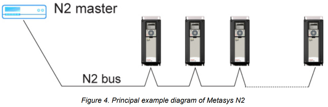
The N2 communications protocol is used by Johnson Controls and others to connect terminal unit controllers to supervisory controllers. It is open to any manufacturer and based upon a simple ASCII protocol widely used in the process control industry.The physical characteristics of the N2 bus are three-wire RS-485 with a maximum of 100 devices over a 4,000-foot distance running at 9,600 bps.Logically, the N2 is a master-slave protocol, the supervisory controller normally being the master. Data is partitioned into common HVAC control objects, such as analoginput, analog output, binary input, and binary output.N2 messaging supports the reading, writing, and overriding of these points.Additionally, there are messages defined to perform uploads and downloads of devices as well as direct memory reads and writes.
N2 technical data
N2 protocol
| Connections andcommunications | Interface | RS-485 |
| Data transfer method | RS-485 MS/TP, half-duplex | |
| Transfer cable | STP (Shielded Twisted Pair), type Belden 9841 or similar | |
| Connector | 2.5 mm2 | |
| Electrical isolation | Functional | |
| Metasys N2 | As described in “Metasys N2 Open System Protocol Specification” | |
| Baud rate | 9600 baud | |
| Addresses | 1 to 255 |
Table 3.
N2 installation
Open the cover of the AC drive.
 The relay outputs and other I/O-terminals may have a dangerous control voltage present even when the drive is disconnected from the mains.
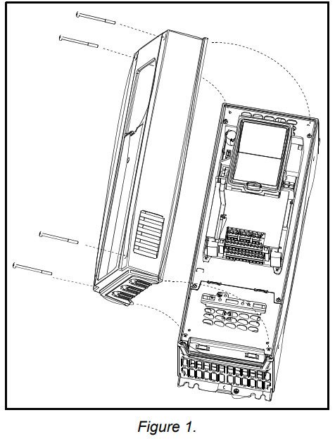
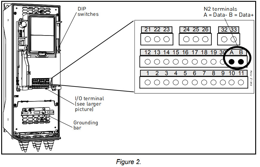
Locate the components that you will need on the AC drive to connect and run the N2 cables.
Prepare for use
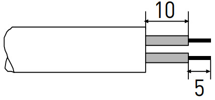
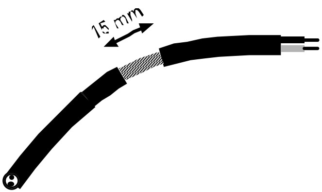
Strip about 15 mm of the N2 cable (see specification on page 7) and cut off the grey cable shield. Remember to do this for both bus cables (except for the last device).Leave no more than 10 mm of the cable outside the terminal block and strip the cables at about 5 mm to fit in the terminals. See the picture below.
Also, strip the cable now at such a distance from the terminal that you can fix it to the frame with the grounding clamp. Strip the cable at a maximum length of 15 mm inches. Do not strip the aluminum cable shield!
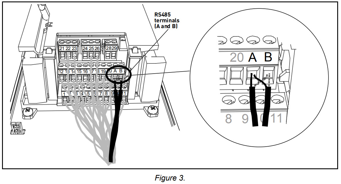
Then connect the cable to its appropriate terminals on AC drive standard terminal block, terminals A and B (A = negative, B = positive). See Figure 3.
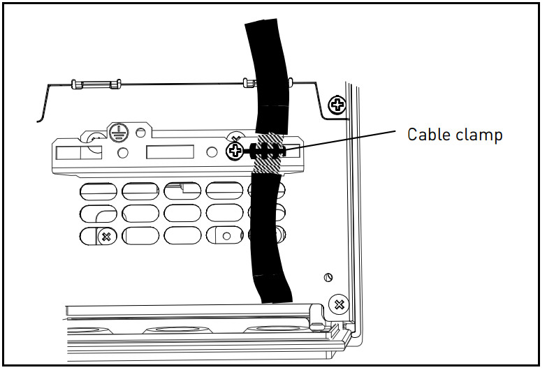
Using the cable clamp included in the delivery of the drive, ground the shield of the RS485 cable to the frame of the AC drive.
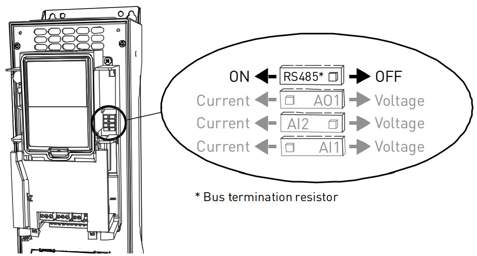
If the drive is the last device on the bus, the bus termination must be set. Locate the DIP switches to the right of the control keypad of the drive and turns the switch for the RS485 bus termination resistor to position ON. Biasing is built in the termination resistor. See also step 9 on page12.
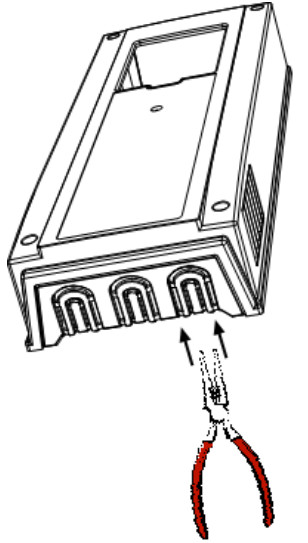
Unless already done for the other control cables, cut free the opening on the AC drive cover for the RS485 cable (protection class IP21).
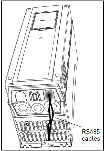
Remount the AC drive cover and run the RS485 cables as shown in the picture.NOTE: When planning the cable runs, remember to keep the distance between the Fieldbus cable and the motor cable at a minimum of 30 cm.
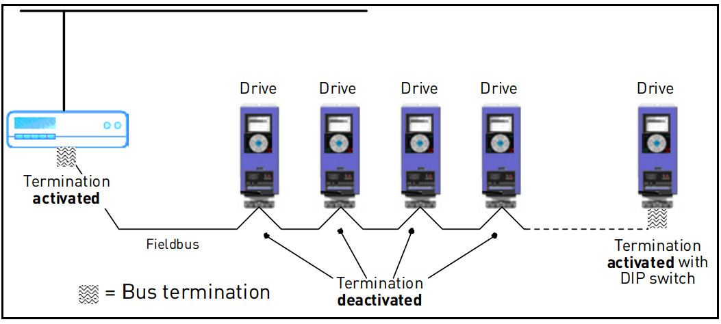
The bus termination must be set for the first and the last device of the Fieldbus line. See the picture below. See also step 6 on page 11. We recommend that the first device on the bus and, thus, terminated was the Master device.
Programming
Basic information on how to use the control keypad you will find in the Honeywell HVAC Application Manual.The navigation path to the Fieldbus parameters may differ from application to application. The exemplary paths below apply to the drive.
- First, ensure that the right Fieldbus protocol is selected.Navigate: Main Menu > I/O and Hardware (M5) > RS-485 (M5.7) > Common settings (M5.7.1) > Protocol (P5.7.1.1) > Edit > (Choose protocol)
- Select ‘Fieldbus control’ as the Remote Control Place.Navigate: Main Menu > Quick Setup (M1) > Rem. Ctrl. Place (P1.15)ORNavigate: Main Menu > Parameters (M3) > Start/Stop Setup (M3.2) > Rem. Ctrl. Place (P3.2.1)
- Choose the source of reference.Navigate: Main Menu > Parameters (M3) > References (M3.3)
- Set Fieldbus parameters in menu M5.7. See below.
N2 parameters and monitoring values (M5.7.3)
| Code | Parameter | Min | Max | Unit | Default | ID | Description |
| PARAMETERS | |||||||
| P5.7.3.1.1 | Slave address | 1 | 255 | 1 | Unique slave device address. | ||
| P5.7.3.1.2 | Communication time-out | 0 | 255 | s | 10 | 0 = Not used |
Table 4. Parameters related to N2
| Code | Parameter | Min | Max | Unit | Default | ID | Description |
| MONITORING VALUES | |||||||
| P5.7.3.2.1 | Fieldbus protocol status | 1 | 3 | 1 | 1 = Stopped | 0 = ‘nit2 = Operational3 = Faulted | |
| P5.7.3.2.2 | Communication status | 0.0 | 100. | 0.0 | 0-99 Number ofmessages with errors 0-999 Number of messages without communication errors | ||
| P5.7.3.2.3 | Invalid data | 0 | |||||
| P5.7.3.2.4 | Invalid commands | 0 | |||||
| P5.7.3.2.5 | Command not accepted | 0 | |||||
| P5.7.3.2.6 | Control word | hex | See page 15. | ||||
| P5.7.3.2.7 | Status word | hex | See page 15. |
N2 parameter descriptions
N2 parameters
P5.7.3.1.1SLAVE ADDRESS
Each slave must have a unique address (from 1 to 255) so that it can be addressed independently from other nodes.
P5.7.3.1.2COMMUNICATION TIME-OUTN2 board initiates a communication error for a time defined with this parameter. ‘0’ means thano fault is generated.
N2 monitoring valuesP5.7.3.2.1FIELDBUS PROTOCOL STATUSFieldbus Protocol Status tells the status of the protocol.
| INITIALIZING | The protocol is starting up |
| STOPPED | The protocol is timeouts or not used |
| OPERATIONAL | Protocol is running |
| FAULTED | A major fault in the protocol requires restarting.If the fault remains contact Technical Support. |
Table 6. FB protocol statuses
P5.7.3.2.2COMMUNICATION STATUSThe Communication status shows how many errors and how many good messages the frequency converter has received.The Communication status includes a common error counter accounts CRC and parity errors and a counter for good messages. Only messages to the current slave in use are united in the good messages.
| Good messages | |
| 0…999 | Number of messages received without errors |
| Bad Frames | |
| 0…99 | Number of messages received with errors |
P5.7.3.2.3INVALID DATAOne of the fields contains a value that is out of the expected range.P5.7.3.2.4INVALID COMMANDSCommand not appropriate for this field or record.
P5.7.3.2.5COMMAND NOT ACCEPTEDDue to problems with the device, the command is ignored.P5.7.3.2.6CONTROL WORDShows the Control Word received from the bus.P5.7.3.2.7STATUS WORDShows the current Status Word that is sent to the bus.
Communications
Features of the N2-Honeywell interface:
- Direct control of drive (e.g. Run, Stop, Direction, Speed reference, Fault reset)
- Full access to all Honeywell parameters
- Monitor Honeywell status (e.g. Output frequency, Output current, Fault code)
Metasys N2 interface
Features of the N2 Interface:
- Direct control of drive (e.g. Run, Stop, Direction, Speed reference, Fault reset)
- Full access to necessary parameters
- Monitor drive status (e.g. Output frequency, Output current, Fault code)
- In standalone operation, or should the polling stop, the overridden values are released after a specified period (about 10 minutes)
Analogue Input (AI)All Analogue Input (AI) points have the following features:
- Support Change of State (COS) reporting based on high and low warning limits.
- Support Change of State (COS) reporting based on high and low alarm limits.
- Support Change of State (COS) reporting based on override status.
- Always considered reliable and never out of range.
- Writing of alarm and warning limit values beyond the range that can be held by the drive’s internal variable will result in having that limit replaced by the “Invalid Float”value even though the message is acknowledged. The net result will be the inactivation of the alarm or warning (the same as if the original out of range value was used).
- Overriding is supported from the standpoint that the “Override Active” bit will be set and the value reported to the N2 network will be the overridden value. However, the value in the drive remains unchanged. Therefore, the N2 system should be set up to disallow overriding AI points or have an alarm condition activated when an AI point is overridden.
- Overriding an AI point with a value beyond the limit allowed by the drive’s internal variable will result in an “Invalid Data” error response and the override status and valuewill remain unchanged.
- Support Change of State (COS) reporting based on the current state.
- Support Change of State (COS) reporting based on an alarm condition.
- Support Change of State (COS) reporting based on override status.
- Always considered reliable.
- Support Change of State (COS) reporting based on override status.
- Always considered reliable.
- Overriding of the AO points is the method used to change a value. Overriding an AO point with a value beyond the limit allowed by the drive’s internal variable will result in an “Invalid Data” error response and the override status and value will remain unchanged. If the overridden value is beyond the drive’s parameter limit but within the range that will fit in the variable, an acknowledged response is given and the value will be internally clamped to its limit.
- An AO point override copies the override value to the corresponding drive parameter. This is the same as changing the value on the keypad. The value is non-volatile and will remain in effect when the drive is turned off and back on. It also remains at this value when the N2 network “releases” the point. The N2 system always reads the current parameter value.
- Support Change of State (COS) reporting based on override status.
- Always considered reliable.
- Overriding BO points control the drive. These points are input commands to the drive.When released, the drive’s internal value remains at its last overridden value.
- Do not support Change of State (COS) reporting.
- Can be overridden and the “Override Active” bit will be set. However, the Internal value is unchanged (Read-Only).
N2 point map
Analog inputs (AI)
| NPT | NPA | Description | Units | Note |
| Al | 1 | Speed Setpoint | Hz | 2 decimals |
| Al | 2 | Output Frequency | Hz | 2 decimals |
| Al | 3 | Motor Speed | Rpm | 0 decimals |
| Al | 4 | Load (power) | % | 1 decimal |
| Al | 5 | Megawatt Hours | MWh | Total Counter |
| Al | 6 | Motor Current | A | 2 decimals |
| Al | 7 | Bus Voltage | V | 0 decimals |
| Al | 8 | Motor Volts | V | 1 decimal |
| Al | 9 | Heatsink Temperature | ° F | 0 decimals |
| Al | 10 | Motor Torque | % | 1 decimal |
| Al | 11 | Operating Days (trip) | Day | 0 decimals |
| Al | 12 | Operating Hours (trip) | Hour | 0 decimals |
| Al | 13 | Kilowatt Hours (trip) | kWh | Trip Counter |
| Al | 14 | Torque Reference | % | 1 decimal |
| Al | 15 | Motor TemperatureRise | % | 1 decimal |
| Al | 16 | FBProcessDataOut11) | -32768 to +32767 | 0 decimals |
| Al | 17 | FBProcessDataOut21 | -32768 to +32767 | 0 decimals |
| Al | 18 | FBProcessDataOut31) | -32768 to +32767 | 0 decimals |
| Al | 19 | FBProcessDataOut41 | -32768 to +32767 | 0 decimals |
| Al | 20 | FBProcessDataOut51) | -32768 to +32767 | 0 decimals |
| Al | 21 | FBProcessDataOut61) | -32768 to +32767 | 0 decimals |
| Al | 22 | FBProcessDataOut71) | -32768 to +32767 | 0 decimals |
| Al | 23 | FBProcessDataOut81 | -32768 to +32767 | 0 decimals |
| 1) These analog inputs are application-specific |
Table 8.
Binary Inputs (BI)
| NPT | NPA | Description | 0 = | 1 = |
| BI | 1 | Ready | Not Ready | Ready |
| BI | 2 | Run | Stop | Run |
| BI | 3 | Direction | Clockwise | Counterclockwise |
| BI | 4 | Faulted | Not Faulted | Faulted |
| BI | 5 | Alarm | Not Alarm | Alarm |
| BI | 6 | Ref. Frequency reached | FALSE | TRUE |
| BI | 7 | Motor running zerospeed | FALSE | TRUE |
| BI | 8 | Flux ready | Not ready | Ready |
Table 9.
Analogue Outputs (AO)
| NPT | NPA | Description | Units | Note |
| AO | 1 | Comms Speed | % | 2 decimals |
| AO | 2 | Current Limit | A | 2 decimals |
| AO | 3 | Minimum Speed | Hz | 2 decimals |
| AO | 4 | Maximum Speed | Hz | 2 decimals |
| AO | 5 | Accel Time | s | 1 decimal |
| AO | 6 | Decel Time | s | 1 decimal |
| AO | 7 | FBProcessDatalN 11) | -32768 to +32767 | 2 decimals |
| AO | 8 | FBProcessDatalN 21) | -32768 to +32767 | 2 decimals |
| AO | 9 | FBProcessDatalN 3’1 | -32768 to +32767 | 2 decimals |
| AO | 10 | FBProcessDatalN 411 | -32768 to +32767 | 2 decimals |
| AO | 11 | FBProcessDatalN 5): | -32768 to +32767 | 2 decimals |
| AO | 12 | FBProcessDatalN 611 | -32768 to +32767 | 2 decimals |
| AO | 13 | FBProcessDatalN 71 | -32768 to +32767 | 2 decimals |
| AO | 14 | FBProcessDatalN 8″ | -32768 to +32767 | 2 decimals |
| AO | 15 | Any parameter Read/Write | Depends onparameter | |
| 1) These Analogue Outputs are application-specific. |
Table 10.
Binary Outputs (BO)
| NPT | NPA | Description | 0 = | 1 = |
| BO | 1 | Comms Start/Stop | Stop | Start |
| BO | 2 | Comms Forward/Reverse | Forward | Reverse |
| BO | 3 | Reset Fault | N/A | Reset |
| BO | 4 | Stop mode information 1 | – | – |
| BO | 5 | Stop mode information 2 | – | – |
| BO | 6 | Force ramp to zero | – | – |
| BO | 7 | Freeze ramp | – | – |
| BO | 8 | Reference to zero | – | – |
| BO | 9 | BusCtrl | – | – |
| BO | 10 | BusRef | – |
Table 11.
Internal Integers (ADI)
| NPT | NPA | Description | Units |
| ADI | 1 | Active Fault Code | – |
| ADI | 2 | Control Word | – |
| ADI | 3 | Status Word | – |
| ADI | 4 | Any parameter ID | – |
Table 12.
Fault tracing
When an unusual operating condition is detected by the AC drive control diagnostics, the drive initiates a notification visible, for example, on the keypad. The keypad will show the ordinal number of the fault, the fault code, and a short fault description.The fault can be reset with the Reset button on the control keypad or via the I/O terminal. The faults are stored in the Fault history menu which can be browsed. The different fault codes you will find in the table below. This fault table presents only the faults related to the Fieldbus in use.NOTE: When contacting the distributor or factory because of a fault condition, always write down all texts and codes on the keypad display and send a description of the problem together with the Drive Info File to Honeywell Technical Support.
Typical fault conditions
| Faultcondition | Possible cause | Remedy |
| Terminationresistor | Missing or excessive termination resistor. | Install termination resistors atboth ends of the Fieldbus line. |
| Cabling | •Supply or motor cables are located too close to the Fieldbus cable•Wrong type of Fieldbus cable•Too long cabling | |
| Grounding | Inadequate grounding. | Ensure grounding in all pointson the net |
| Connections | Faulty connections.•Excessive stripping of cables•Conductors in wrong terminals•Too loose connections of conductors | |
| Parameter | •Faulty address•Overlapping slave addresses•Wrong baud rate•Wrong control place selected |
Table 13. Typical fault conditions
RS-485 bus biasing
When none of the devices on the RS-485 bus is sending data all devices are in idle status. This being the case, the bus voltage is in an indefinite state, usually near 0 V due to the termination resistors. This may cause problems in character reception because the single characters in serial communication begin with start bit referring to bus status ‘0’ with voltage of less than 200mV whereas the bus status ‘1’ corresponds to bus voltage of more than +200mV. The RS485 standard considers the voltage interval -200mV…+200mV as an undefined state.Bus biasing is therefore needed to maintain the voltage in status ‘1’ (above +200mV) also between the mes- sages.To bias the bus you will have to add a separate active termination resistor specifically designed for the RS-485 bus (e.g. Siemens active RS 485 terminating element (6ES7972-0DA00-0AA0).
Other fault conditions
The following fault tracing diagram will help you to locate and fix some of the most usual problems. If the problem persists contact your local distributor.

Quick setup
Following these instructions, you can easily and fast set up your N2 bus for use:
| 1 | Choose control place.A.Press LOC/REM button on keypad to select Remote Control PlaceB.Select Fieldbus as remote control place: Main Menu > Quick Setup (M1) > Rem. Ctn. Place (P1.15) > FieldbusCTRL |
| 2 | Make these settings in the master softwareC.Set Control Word to ‘0’ (ADI2)D.Set Control Word to 1′ (ADI2)E.Frequency converter status is RUNF.Set Reference value to ‘50.00%’ (A01)G.Output Frequency (Al2) is 25.00Hz if MinFreq is 0.00 Hz and MaxFreq is 50.00 HzH.Set Control Word to ‘0’ (ADI2)I.Frequency converter status is STOP. |
Annex
Process Data IN (Master to Slave)Use of Process Data In variables depends on the used application. The configuration of the data is free.Process Data OUT (Slave to Master)Use of Process Data Out variables depends on the used application.The Fieldbus Master can read the frequency converter’s actual values using process data variables.Control applications use process data as follows:
| ID | Data | Value | Unit | Scale |
| 2104 | Process data OUT 1 | Output Frequency | Hz | 0,01 Hz |
| 2105 | Process data OUT 2 | Motor Speed | rpm | 1 rpm |
| 2106 | Process data OUT 3 | Motor Current | A | 0,1 A |
| 2107 | Process data OUT 4 | Motor Torque | % | 0,1 % |
| 2108 | Process data OUT 5 | Motor Power | % | 0,1 % |
| 2109 | Process data OUT 6 | Motor Voltage | V | 0,1 V |
| 2110 | Process data OUT 7 | DC link voltage | V | 1 V |
| 2111 | Process data OUT 8 | Active Fault Code | – |
Table 14. Process Data OUT variables
Find out moreFor more information on Honeywell’s variable frequency drives and otherHoneywell products, visit us online athttp://ecc.emea.honeywell.com
By using this Honeywell literature, you agree that Honeywell will have no liability for any damages arising out of your use or modification to, the literature. You will defend and indemnify Honeywell, its affiliates and subsidiaries, from and against any liability, cost, or damages, including attorneys’ fees, arising out of, or resulting from, any modification to the literature by you.
Automation and Control SolutionsHoneywell GmbHBöblinger Str. 1771101 Schönaich, GermanyTelephone (49) 7031 637 01Telefax (49) 7073 637 493www.ecc.emea.honeywell.com
EN2B-0374GE51 R1210April 2018© 2018 Honeywell International Inc.
![]()
[xyz-ips snippet=”download-snippet”]