
![]()
PCMOD Interface Module
INSTALLATION INSTRUCTIONS
BEFORE INSTALLATION
Review the following before installing the W7220-PCMOD.I/OThe W7220-PCMOD tool is connected to the S-Bus device using 2 non-polarity 18-22 ga. wires via 6- pin connector supplied with the product. The W7220-PCMOD tool is connected to the personal computer using a USB cable provided with the product. The PC tool is powered through the Sylk device and USB connection to the personal computer.NOTE: A S-Bus device is any Honeywell component or controller that is compatible with the W7220PCMOD tool.If you have a question contact your local distributor or the Honeywell hotline at 888-516-9347.
This document describes the wiring, basic operation, and setup for the PC tool software module. This tool is used with SBus that transfers information from the Sylk device and communicates it to a personal computer via USB cable.
Refer to Fig. 1 for wiring configurations.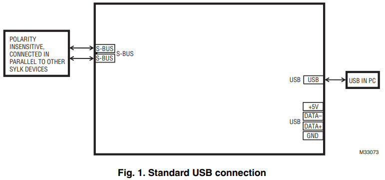

INSTALLATION AND SETUP
- Download PC tool software from http://customer.honeywell.com/economizertools to your personal computer.
- NOTE: OEM and Field tools are the same hardware but use different programs and are used for different purposes. The password for the Field software is password. For the OEM password call your Honeywell OEM representative.During initial software, the installation makes sure to check the box to create a desktop shortcut and check on “Install/Remove TUSB Drivers” on the installation screen.If you are repeating the installation of the software or not sure if the TUSB drivers are on the computer you are using, follow the steps in 4 below.If you do not want to run the application immediately, unselect the “Run Jade Configuration tool” before clicking on FINISH.After successfully downloading the software to your computer you will need to restart your computer.Close all programs and restart your computer.For additional instructions contact your local distributor or the Honeywell hotline at 888-516-9347.
- Follow the next steps in order.2. Connect the W7220-PCMOD interface module to your computer using the USB cable provided.3. Connect the W7220-PCMOD tool to your S-Bus device using 2 non-polarity 18-22 gauge wires and power the Sylk devise. Start configuration tool. If you get a message stating PC-tool cannot get firmware revision, then follow the steps in 4 below. The wires can be up to 100 feet without protection and up to 400 feet using twisted-pair wire.
- To verify the correct port on your computer:• Press the Windows key and the Pause key at the same time on your keyboard.• Click Device Manager that appears on the left side of the screen (if using Windows XP the System the properties window will appear; click on hardware, then device manager).• Click Ports from Device window pop up.• Note the Com port assigned to TUSB3410. Close the Device Manager screen.NOTE: If the TUSB3410 port does not appear on your ports then the PC tool has not been connected properly.
- Go to the configuration tool and choose the matching to comport to TUSB3410 from the Settings menu.
For Specific instructions refer to the Honeywell E-learning module at: http://customer.honeywell.comNOTE: If the full page does not appear on your computer viewing screen – go to the upper right corner and maximize the page using the minimize/maximize boxes. The page will re-size and vertical and horizontal scrolling bars will appear on the right side and bottom of the page.
There are features in the Jade economizer controllers that can only be turned on or off and adjusted using the PC tool.NOTE: The firmware in both the Jade and the PC tool needs to be current for all features to be configurable. If using different, earlier versions of Jade and PC tool, then the supported features will be limited to the version of Jade firmware. The PC tool firmware is backwardly compatible with all versions of the Jade firmware.If you chose a feature using the PC tool firmware that is not supported by an older version of the Jade controller, you will receive a message stating that the feature is not supported.These features are found on the economizer and the configuration pages for the Trade version and are dependent on the version of firmware used. They are found on the configuration page for the OEM version. The Trade version location is noted in the description below.Features available only using the PC tool configurator:
- Ability to choose W7220 (Jade full-featured) or W7218 (Jade Lite de-featured Model) (On configuration page for Trade version)THE FOLLOWING FEATURES ARE NOT AVAILABLE ON THE W7218 JADE LITE PRODUCT. THEY ARE ONLY AVAILABLE WITH THE JADE CONTROLLER.
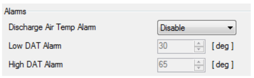
- Ability to choose discharge air temperature alarm. This feature creates an alarm on the Jade if the temperature of the discharge air goes above or below preset limits. The operator has the ability to choose from disabling, enable both high and low, enable high only, or enable low only. (On economizer page for Trade version)a. This feature will only be active when the Jade is in the OCC (occupied) mode.b. Choose “disable” to turn off the alarm feature.c. Choose “Enable hi” to only alarm on a high-temperatured.Choose “Enable lo” to only alarm on a low-temperaturee.Choose “Enable” to alarm on a high and a low temperature.f. Example: If the Jade is “Enable” the operator will input a high DAT temperature and a low DAT temperature. If the high temperature is programmed for 80F and the low temperature is programmed for 30F then if the discharge air temperature sensor senses 81F then a DAT hi-temp alarm will display on the LCD on Jade nd if the discharge air temperature senses 29F then a DAT lo temp alarm will display on the LCD on Jade.g. The operator can choose high only or low only or disable the alarm feature if not using a DAT sensor in the system.

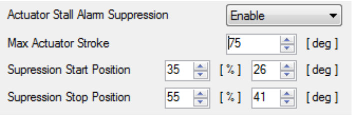
- Ability to turn on and set range in damper position where an actuator stall alarm will be disabled. (On economizer page for Trade version)
a. For applications where the damper does not travel a full 90 degrees in the application and to avoid nuisance alarms when the damper stalls, the operator has the ability to enable a stall alarm, to input the full stroke (in degrees) of the damper movement and to choose the start and stop position of the alarm suppression.b. Example: The operator chooses to “enable” the suppression alarm, sets the damper at 75 degrees full travel and sets the start suppression at 35% open (26 degrees) and suppression stop at 55% open (41 degrees) IF the damper stalls between 35% and 55% open and alarm will be displayed on the Jade LCD.
-
Actuator slipping on a shaft or disconnected from the damper.(On economizer page for Trade version)The actuator disconnected from the damper or slipping on the shaft feature can be enabled or disabled. If the operator chooses to “enable” the feature then the Jade system will complete a system air temperature check when the conditions are right and command the damper to open or close. If there is the expected change in the system air temperatures then the actuator is connected to the damper. If the expected system air temperature changes do not occur then an actuator slippage alarm is displayed on the LCD of the Jade. The sensitivity of the system can be set to HIGH, STANDARD, or LOW. HIGH means the system will check only 5 times for the damper to move before displaying an alarm, LOW means the system will check 20 times for the damper to move before displaying an alarm and STANDARD is 10 times before the alarm is displayed.
-
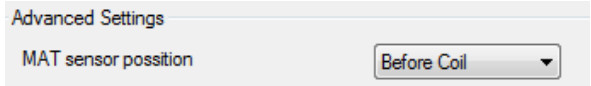
The PC tool allows the operator to choose if the sensor is placed in the mixed air (before the coil) or in the discharge air (after the oil). The operator has the ability to choose”AUTO” where the system determines where the sensor is located based on the conditionsor the operator can choose “BEFORE THE COIL”. (On configuration page for Trade version) This solves a problem caused by placing the mixed air sensor after the cooling coil (in discharge air). Without this feature and the MA sensor is placed after the coolingcoil, then when the cooling coil is energized, the system would lose the benefits of economizing.
-
The damper threshold feature (Adaptive Integral Action) is the difference in the mixed air temperature reported by the MAT sensor and the MAT setpoint and affects the rate of the opening and closing of the damper. Setting a lower (2 degrees) transfer rate between the actual MAT sensor reading and the MAT setpoint means the damper is closing and opening faster and a larger transfer rate (up to 20 degrees) between the sensor reading and the setpoint means the damper is opening and closing slower. This is used in applications where there is a large MA space or there is a long duct between the OA and the MA causing a delay. (On configuration page for Trade version)


PCMOD INTERFACE MODULE
By using this Honeywell literature, you agree that Honeywell will have no liability for any damages arising out of your use or modification to, the literature. You will defend and indemnify Honeywell, its affiliates and subsidiaries, from and against any liability, cost, or damages, including attorneys’ fees, arising out of, or resulting from, any modification to the literature by you.
Automation and Control SolutionsHoneywell International Inc.1985 Douglas Drive NorthGolden Valley, MN 55422customer.honeywell.com
![]() ® U.S. Registered Trademark© 2014 Honeywell International Inc.62-0409—07 M.S. Rev. 12-14Printed in the United States
® U.S. Registered Trademark© 2014 Honeywell International Inc.62-0409—07 M.S. Rev. 12-14Printed in the United States
[xyz-ips snippet=”download-snippet”]