
Installation Instructions for the
Quadrature Speed and Direction Sensors 32309314
SNG-Q Series Issue E
General Information
Honeywell’s SNG-Q Series Quadrature Speed and Direction Sensors are designed to provide both speed and direction information. Speed information is provided from digital square wave outputs; direction is provided using a quadrature output with signals 90° phase shifted from each other. With the quadrature output, target direction is determined by output lead/lag phase shifting.
The product is designed for applications where enhanced accuracy is required to detect small target features. This accuracy is enabled by dual differential Hall-effect sensor IC technology. The SNG-Q Series is designed for a wide operating temperature range, robust electrical noise immunity and industry leading environmental sealing capability.
This product includes an O-ring seal for pressure applications, and a fixed mounting flange for simple installation using one fastener.
Table 1. Electrical Specifications
| Characteristic | Parameter | Comment |
| Supply voltage | 4.5 V to 26 V | — |
| Output signal:
type duty cycle¹
phase shift
high low: SNG-QPLA/QPCA/ QPMB/QPDB load current rise time fall time frequency |
square wave 50% ±10%
90° ±45°
≥Vs – 0.5 V
≤0.5 V ≤1.75 V 40 mA max. 10 us max. 5 us max. 3 Hz to 20 kHz |
Two channel, phase shifted by 90° either channel, may lead or lag. Dependent on target geometry and sensor-to-target orientation; see Figures 2, 3, 4, 5, 6, 7, 8, 9 for recommended orientation. Dependent on target geometry and sensor-to-target orientation; see Figures 2, 3, 4, 5, 6, 7, 8, 9 for recommended orientation. — —
Applies to each output at all conditions. 1 kOhm pull-up resistor, dependent on load resistor. 1 kOhm pull-up resistor, dependent on load resistor. Frequencies >10 kHz may be dependent on target geometry and air gap. |
| Short circuit protection | 50 mA max. | —
|
| Supply current:
normal max. |
12 mA 18 mA |
all conditions |
| Reverse voltage | -26 V max. | 10 min duration |
¹Duty cycle = Time high/time total.
Table 2. Mechanical Specifications
| Characteristic | Parameter |
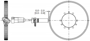
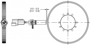
| Sensing air gap | 0,0 mm to 2,0 mm [0.0 in to 0.08 in] |
| Target:
width1 slot width2 tooth width2 tooth height3 |
>5,0 mm [0.20 in] recommended; 12,7 mm [0.5 in] typ. 2,0 mm [0.08 in] min. 2,0 mm [0.08 in] min. >3,0 mm [0.12 in] recommended; 5,0 mm [0.20 in] typ. |
| Materials:
housing bushing O-ring cable4 |
PBT brass fluorocarbon with PTFE coating, ø11,8 mm [ø0.47 in] OD x ø1,80 mm [ø0.07 in] CS EVA, four conductor, 36 AWG, 28 strand, ø5,2 mm [ø0.20 in] jacket |
| Mounting:
bore size5 torque |
ø15,15 mm to ø15,40 mm [ø0.60 in to ø0.61 in] 10 N m [88.5 in-lb] max. with M6 X 1.0 bolt |
¹Narrower targets may limit axial offsets.²Other geometry may be suitable.³Shorter tooth heights may limit maximum air gap performance.4Applies to SNG-QPLA-001, SNG-QPCA-001, SNG-QPMB-000, SNG-QPDB-000, and SNG-QPDB-002.5Application dependent.
Table 3. Environmental Specifications
| Characteristic | Condition | Parameter |
| EMI:
radiated immunity bulk current injection ESD |
ISO 11452-2, 400 MHz to 1 GHz ISO 11452-4, 1 MHz to 400 MHz ISO 10605, Section 9 conforms to CE Mark standards EN60947-5-2:2007 and EN 60947-5-2/A1:2012 |
100 V/m 100 mA ±8 kV contact, ±15 kV air |
| Operating temperature | — | -40°C to 150°C [-40°F to 302°F] |
| Thermal shock, air to air | -40°C to 150°C [-40°F to 302°F], 60 min. soak, <3 s transfer | 500 cycles |
| Humidity | 95% humidity at 38 °C [100 °F] | 240 hr |
| Salt fog | 5% salt solution by mass at 35 °C [95 °F] | 96 hr |
| Thermal saline dunk | 100°C to 25°C [212°F to 77°F] air to liquid, 5% saline | 10 cycles |
| High temperature exposure with power | 150°C [302°F], 13.5 Vdc, 1 kOhm load | 500 hr |
| Vibration | 3 perpendicular axes, 48 hr per axis | 29.28 GMS, 50 Hz to 2000 Hz
MIL-STD-202-214 |
| Degree of protection | — | IP69K |
| Resistance to fluids | — | general under-the-hood automotive fluids |
Figure 1. Sensor Output (All catalog listings)
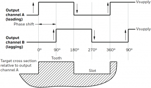
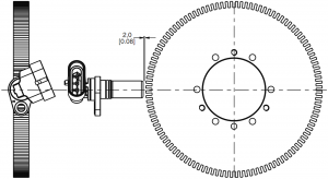
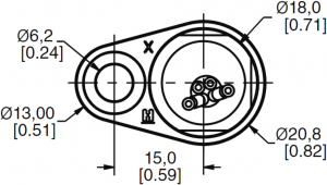
Figure 2. Possible Mounting Orientations
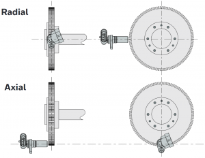
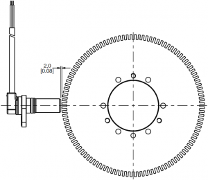
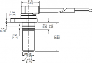
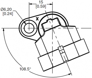
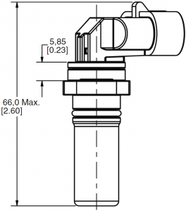
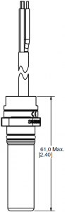
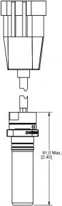
Figure 3. SNG-QPLA-000 Mounting Dimensions (For reference only: mm/[in].)


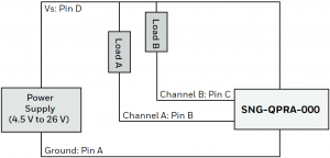
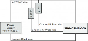
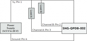
Circuit Diagram
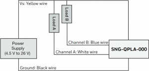
Note: The load resistor values should be such that the output current does not exceed the maximum load current of 40 mA.
Use Ohm’s Law to calculate the load resistor based on the supply/load voltage used:
R = V / 0.04 A
Leadwire Assignment
|
Yellow |
Black | White | Blue |
| Vsupply | Ground | Channel A |
Channel B |
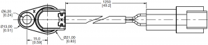
Figure 4. SNG-QPCA-001 Mounting Dimensions (For reference only: mm/[in].)
![]()


Circuit Diagram
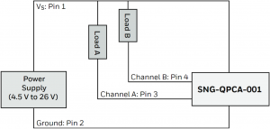
Note: The load resistor values should be such that the output current does not exceed the maximum load current of 40 mA.
Use Ohm’s Law to calculate the load resistor based on the supply/load voltage used:
R = V / 0.04 A
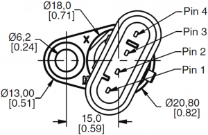
Deutsch DTM04-4P Pinout(mating connector is Deutsch DTM06-4S)
|
Pin 1 |
Pin 2 | Pin 3 | Pin 4 |
| Vsupply | Ground | Channel A |
Channel B |
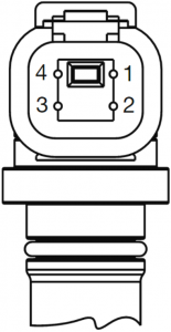
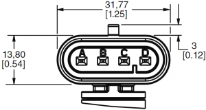
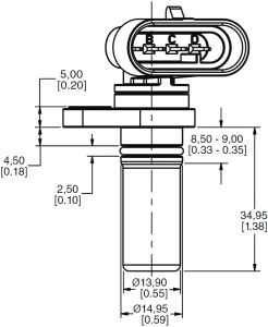
Figure 5. SNG-QPRA-000 Mounting Dimensions (For reference only: mm/[in].)
Circuit Diagram
Note: The load resistor values should be such that the output current does not exceed the maximum load current of 40 mA.
Use Ohm’s Law to calculate the load resistor based on the supply/load voltage used:
R = V / 0.04 A
Amp Superseal 1.5 Connector Pinout(mating connector is Amp Superseal 1.5 282088)
|
Pin A |
Pin B | Pin C | Pin D |
| Ground | Channel A | Channel B |
Vsupply |
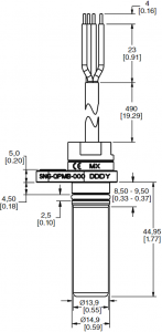
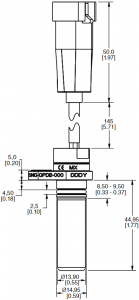
Figure 6. SNG-QPMB-000 Mounting Dimensions (For reference only: mm/[in].)

Circuit Diagram
Note: The load resistor values should be such that the output current does not exceed the maximum load current of 40 mA.
Use Ohm’s Law to calculate the load resistor based on the supply/load voltage used:
R = V / 0.04 A
Leadwire Assignment
|
Yellow |
Black | White | Blue |
| Vsupply | Ground | Channel A |
Channel B |
Figure 7. SNG-QPDB-000 Mounting Dimensions (For reference only: mm/[in].)

Circuit Diagram

Note: The load resistor values should be such that the output current does not exceed the maximum load current of 40 mA.
Use Ohm’s Law to calculate the load resistor based on the supply/load voltage used:
R = V / 0.04 A
Amp Superseal 1.5 282106 Pinout(mating connector is Amp Superseal 1.5 282088)
|
Pin 1 |
Pin 2 | Pin 3 | Pin 4 |
| Vsupply | Channel B | Channel A |
Ground |
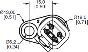
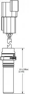
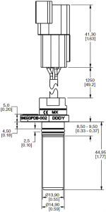
Figure 8. SNG-QPDB-002 Mounting Dimensions (For reference only: mm/[in].)
Circuit Diagram
Note: The load resistor values should be such that the output current does not exceed the maximum load current of 40 mA.
Use Ohm’s Law to calculate the load resistor based on the supply/load voltage used:
R = V / 0.04 A
Deutsch DTM04-4P Pinout(mating connector is Deutsch DTM06-4S)
|
Pin 1 |
Pin 2 | Pin 3 | Pin 4 |
| Vsupply | Channel B | Channel A |
Ground |
 WARNING
 WARNING
PERSONAL INJURY
DO NOT USE these products as safety or emergency stop devices or in any other application where failure of the product could result in personal injury.Failure to comply with these instructions could result in death or serious injury.
Warranty/Remedy
Honeywell warrants goods of its manufacture as being free of defective materials and faulty workmanship during the applicable warranty period. Honeywell’s standard product warranty applies unless agreed to otherwise by Honeywell in writing; please refer to your order acknowledgement or consult your local sales office for specific warranty details. If warranted goods are returned to Honeywell during the period of coverage, Honeywell will repair or replace, at its option, without charge those items that Honeywell, in its sole discretion, finds defective.The foregoing is buyer’s sole remedy and is in lieu of all other warranties, expressed or implied, including those of merchantability and fitness for a particular purpose. In no event shall Honeywell be liable for consequential, special, or indirect damages.
While Honeywell may provide application assistance personally, through our literature and the Honeywell web site, it is buyer’s sole responsibility to determine the suitability of the product in the application.
Specifications may change without notice. The information we supply is believed to be accurate and reliable as of this writing. However, Honeywell assumes no responsibility for its use.
For more information
Honeywell Advanced Sensing Technologies services its customers through a worldwide network of sales offices and distributors.For application assistance, current specifications, pricing or the nearest Authorized Distributor, visit our website or call:Asia Pacific +65 6355-2828Europe +44 (0) 1698 481481USA/Canada +1-800-537-6945
Honeywell Advanced Sensing Technologies830 East Arapaho RoadRichardson, TX 75081sps.honeywell.com/ast
32309314-E-EN | E | 05/21© 2021 Honeywell International Inc.
References
[xyz-ips snippet=”download-snippet”]