Honeywell RLV3100 Digital Thermostat Installation Guide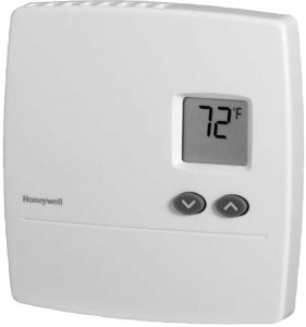

Read and save these instructions.For help please visit yourhome.honeywell.com
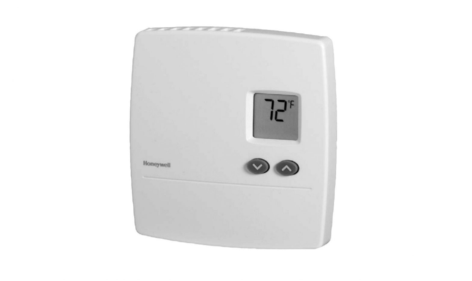
Application
The RLV3100 thermostat can be used to control an electric heating system such as an electric baseboard heater, a radiant ceiling, a radiant floor, a convector, etc.
The thermostat cannot be used with the following:
- a resistive load under 2 A
- a resistive load over 12.5 A
- systems driven by a contactor or a relay (inductive load)
- fan-forced heating systems
- central heating systems
Supplied Parts
- One (1) thermostat
- Two (2) 6-32 mounting screws
- Two (2) solderless connectors

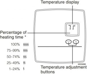
- The thermostat displays the percentage of heating time required to maintain the desired temperature. For example, is displayed when heating is activated 40 percent of the time.
![]() ATTENTION: MERCURY RECYCLING NOTICE
ATTENTION: MERCURY RECYCLING NOTICE
This product does not contain mercury. However, this product may replace a product that contains mercury. Mercury and products containing mercury should not be discarded in household trash.
For more information on how and where to properly recycle a thermostat containing mercury in the United States, please refer to the Thermostat Recycling Corporation at www.thermostat-recycle.org.
For mercury thermostat recycling in Canada, please refer to Switch the Stat at www.switchthestat.ca
Customer assistance
If you have any questions about the operation of your thermostat, please go to http://yourhome.honeywell.com, or call Honeywell Customer Care toll-free at 1-800-468-1502.
Installation
![]() TURN OFF POWER OF THE HEATING SYSTEM AT THE MAIN POWER PANEL TO AVOID ELECTRIC SHOCK.
TURN OFF POWER OF THE HEATING SYSTEM AT THE MAIN POWER PANEL TO AVOID ELECTRIC SHOCK.
Loosen the screw underneath the thermostat and separate the front plate from the base plate.

![]() The screw cannot be completely removed.
The screw cannot be completely removed.
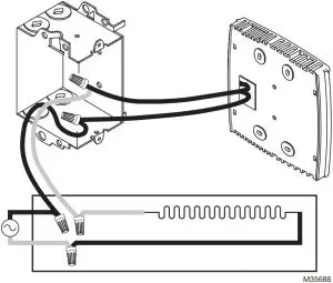
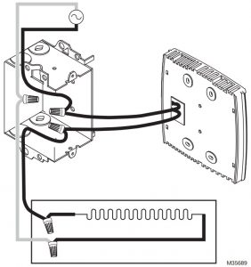
Connect the thermostat wires to the power and to the load using solderless connectors for copper wires. The thermostat wires are not polarized; meaning either wire can be connected to the load or to the power supply.
![]() All cables and connections must comply with local electrical codes. This thermostat has tinned copper wires for line and load connections. Special CO/ALR solderless connectors must be used if these wires will be connected to aluminium conductors.
All cables and connections must comply with local electrical codes. This thermostat has tinned copper wires for line and load connections. Special CO/ALR solderless connectors must be used if these wires will be connected to aluminium conductors.
- Fig. 1 2-wire Installation.
- Fig. 2 4-wire Installation.
Mount the back plate to the electrical box using the provided screws. Insert the screws through the left or right pair of mounting holes of the back plate.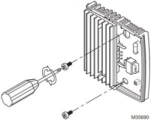
Set the switch on the back of the front plate to °C or °F to select the temperature display format.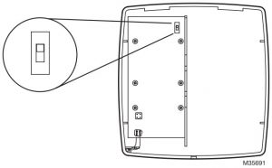
Re-install the front plate of the thermostat on the base plate and secure it in place with the screw underneath the thermostat.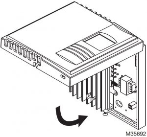
![]() If there is a protective film or sticker on the display, peel it off.
If there is a protective film or sticker on the display, peel it off.
Apply power to the heating system. Verify the installation by checking that the heater can be turned On and Off by raising and lowering the setpoint using the ![]() buttons.
buttons.
Temperature Display and Setting
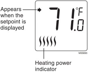
The thermostat normally displays the actual (measured) temperature.
- To view the set temperature (setpoint),press once on either of the temperature adjustment buttons.
- To change the setpoint, press the appropriate button until the desired value is displayed
The display is backlit for 10 seconds when you press any button.
![]() Keep the thermostat’s air vents clean and free from obstructions at all times.
Keep the thermostat’s air vents clean and free from obstructions at all times.
Power Outage
The setpoint is stored in non-volatile memory and is not erased when there is a power outage.
Troubleshooting
| PROBLEM | SOLUTIONS |
| Thermostat is hot. | This is normal. Under normal operation, the thermostat housing can reach a temperature between 95 °F (35 °C) and 104 °F (40 °C). |
| Displayed temperature is wrong. | Correct if any the following conditions applies:
|
| Display disappears and reappears after a few minutes. | The thermal protection device on the heater was temporarily opened. This can happen if the heater is obstructed by furniture or curtain and has overheated, or if the heater’s thermal protection device is too sensitive. |
| Display looks faded when heating is activated. | The heating system is less than the required minimum load. This thermostat cannot be used below that rating. |
Specifications
- Supply: 240 VAC, 60 Hz
- Minimum load: 500 W (2 A resistive only)
- Maximum load: 3000 W (12.5 A resistive only)
- Display range: 32 to 122°F ( 0 to 50°C)
- Setpoint range: 40 to 85°F (5 to 30°C)
- Resolution: 1°F (0.5°C)
- Storage: -4 to 120°F (-20 to 50°C)
- Dimensions: 5.0 x 4.8 x 1.2 inches (126 x 121 x 31 mm)
- Approval: c UL us
1-year limited warranty
Honeywell warrants this product, excluding battery, to be free from defects in the workmanship or materials, under normal use and service, for a period of one (1) year from the date of purchase by the consumer. If at any time during the warranty period the product is determined to be defective or malfunctions, Honeywell shall repair or replace it (at Honeywell’s option).
If the product is defective,
- return it, with a bill of sale or other dated proof of purchase, to the place from which you purchased it; or
- call Honeywell Customer Care at 1-800-468-1502.Customer Care will make the determination whether the product should be returned to the following address:Honeywell Return Goods, Dock 4 MN10-3860, 1885 Douglas Dr. N., Golden Valley, MN 55422, or whether a replacement product can be sent to you.
This warranty does not cover removal or reinstallation costs. This warranty shall not apply if it is shown by Honeywell that the defect or malfunction was caused by damage which occurred while the product was in the possession of a consumer
Honeywell’s sole responsibility shall be to repair or replace the product within the terms stated above.HONEYWELL SHALL NOT BE LIABLE FOR ANY LOSS OR DAMAGE OF ANY KIND, INCLUDING ANY INCIDENTAL OR CONSEQUENTIAL DAMAGES RESULTING, DIRECTLY OR INDIRECTLY, FROM ANY BREACH OF ANY WARRANTY, EXPRESS OR IMPLIED, OR ANY OTHER FAILURE OF THIS PRODUCT.states do not allow the exclusion or limitation of incidental or consequential damages, so this limitation may not apply to you.
THIS WARRANTY IS THE ONLY EXPRESS WARRANTY HONEYWELL MAKES ON THIS PRODUCT. THE DURATION OF ANY IMPLIED WARRANTIES, INCLUDING THE WARRANTIES OF MERCHANTABILITY AND FITNESS FOR A PARTICULAR PURPOSE, IS HEREBY LIMITED TO THE ONE-YEAR DURATION OF THIS WARRANTY.
Some states do not allow limitations on how long an implied warranty lasts, so the above limitation may not apply to you. This warranty gives you specific legal rights, and you may have other rights which vary from state to state.
If you have any questions concerning this warranty, please write Honeywell Customer Relations, 1985 Douglas Dr, Golden Valley, MN 55422 or call 1-800-468- 1502.
[xyz-ips snippet=”download-snippet”]