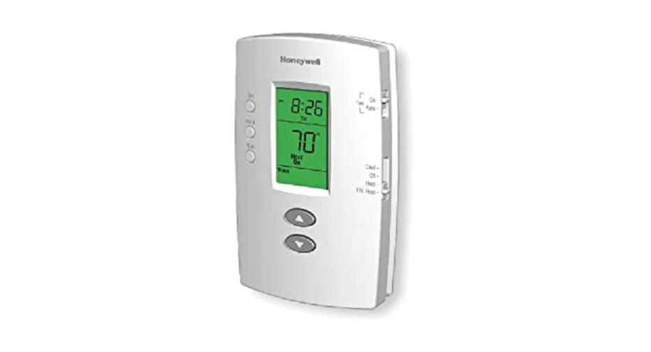
Honeywell RTH111/RTH221 Programmable and Non-programmable Thermostats Installation Guide
Introduction
The RTH111/RTH221 thermostats can be used to control:
- a gas, oil or electric furnace — 2 or 3 wires
- a central air conditioner — 2 or 3 wires
- a hot water system (steam or gravity) with or without pump — 2 wires
- a millivolt system — 2 wires
- a central heating system with air conditioning — 4 or 5 wiresNOTE: This thermostat is not compatible with heat pumps or multi-stage systems.
Installation
![]() CAUTION: ELECTRICAL HAZARDCan cause electric shock or equipment damage. Disconnect power before beginning installation.
CAUTION: ELECTRICAL HAZARDCan cause electric shock or equipment damage. Disconnect power before beginning installation.
Removing the old thermostat
IN ORDER TO AVOID ANY RISK OF ELECTRIC SHOCK, CUT POWER TO THE HEATING SYSTEM.
- Remove the old thermostat to access the wires.WARNING: If the old thermostat was mounted onto an electrical box, it might have been powered by 120/240 volts. In this case, this thermostat cannot be used. If you are unsure of the voltage supplied to your thermostat, contact an electrician.
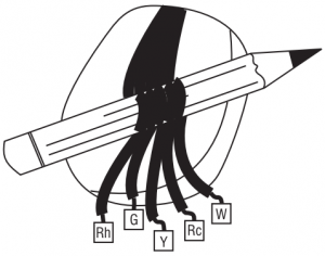
- Identify and label each wire (with the corresponding letter on the thermostat terminal) and remove it from the terminal.NOTE 1: Ignore wire colors, use only letter designations to identify wire types.NOTE 2: If any wires are not attached to the terminals of your old thermostat, you do not need to label them as they will not be connected to your new thermostat.
- If necessary, strip the end of each wire (maximum of 1/4 inch).
- Wrap the loose wires around a pencil to prevent them from falling into the wall.
- If the hole in the wall is too big, insulate it using a non-flammable material to avoid air draughts behind the thermostat.
 MERCURY NOTICEIf this product is replacing a control that contains mercury in a sealed tube, do not place the old control in the trash. Contact your local waste management authority for instructions regarding recycling and proper disposal.
Wallplate installation
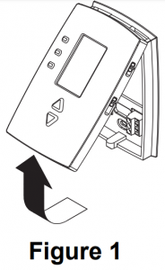
- Loosen the locking screw at the bottom of the thermostat. Note the screw is captive and cannot be removed from the wallplate.
- Separate the thermostat from the wallplate as per Figure 1.
- Position the wallplate against the wall and mark hole positions with a pencil.NOTE: Levelling is for esthetics only and will not affect theperformance of the thermostat.
- Drill holes at the marked positions and insert supplied wall anchors.
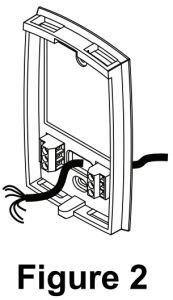
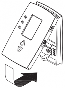
- Pass the wires through the large opening at the bottom center of the wallplate as per Figure 2.
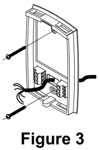
- Secure the wallplate to the wall with supplied mounting screws as per Figure 3.
Wiring
It is important that you match the wire labels with the corresponding terminals on the thermostat.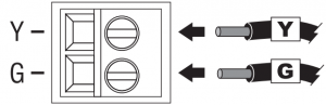
 NOTE: Depending on your system, you might not need to connect to all terminals.
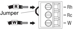
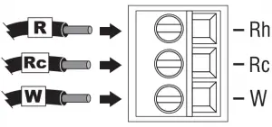
Remove the jumper wire between Rh and Rc terminals if you have both Rh and Rc wires as shown in the following illustration.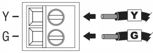
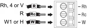
If a wire label does not match a terminal designation on the thermostat, refer to the following illustration to find the corresponding alternate wire label.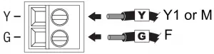
![]() Do not connect wires identified as C, C1, X or B as these wires are not used with this thermostat. Wrap the bare end of these wires with electrical tape, so they cannot touch and short out other wires.
Do not connect wires identified as C, C1, X or B as these wires are not used with this thermostat. Wrap the bare end of these wires with electrical tape, so they cannot touch and short out other wires.
Fan operation setting
NOTE: This setting is not applicable if there is no fan connected tothe G terminal.The jumper is located on the back of the thermostat faceplate. It determines how the fan operates when placed in Automatic mode.
- HG (factory setting): Leave the jumper in this position for gas or oil heating systems. In this position, the heating system controls the fan operation and activates the fan only when the plenum air is sufficiently warm.
- HE: Place the jumper to this position for electric heating systems. In this position, the thermostat activates the fan only when there is a call for heat.
Incorrect jumper setting:
- Incorrect HE setting in a gas or oil heating system: When heating starts, you will initially feel cold air coming out of the vents as the fan is running before the furnace has enough time to heat up the air.
- Incorrect HG setting in an electric heating system: The fan will not run when heating is activated.
Battery installation
Install two AAA batteries on the back of the thermostat faceplate as shown.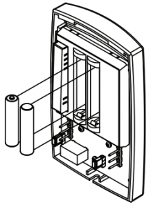
Thermostat mounting
- Align the two brackets on the top of the thermostat with the corresponding slots on the top of the wallplate.
- Push the faceplate against the wallplate.
- Tighten the screw at the bottom of the thermostat.
Follow the procedure below to personalize and configure the thermostat according to the heating/cooling system.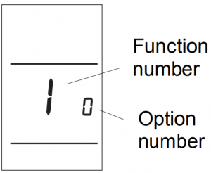
- Press and simultaneously (for three seconds) until the display appears as shown on the right.
- Press or to change the option.
- Press and for one second to advance to the next function.
- When the last function is displayed, press and for three seconds to save any changes and exit the menu.NOTE: If you do not press any button for 60 seconds while you are in the setup menu, the thermostat automatically saves any changes made and exits the menu. For the RTH221 programmable model only, at any time you can save the changes and exit by pressing the Run button.
Function
Default setting Options
Temperature display format
0
0: Fahrenheit1: Celsius
Time display format 1
0
0: 12-hour display1: 24-hour display
Heating cycles per hour 2
5
- 1: 60 min (steam, gravity)
- 3: 20 min (hot water, 90%+ high efficiency furnace)
- 5: 12 min (gas or oil)
- 9: 6.7 min (electric)
1 Applies to RTH221 programmable model only.2 The cooling cycle is fixed at 3 cycles per hour
 This is a legacy product document supported by Resideo. It is no longer manufactured
[xyz-ips snippet=”download-snippet”]