![]()
This is a legacy product documentsupported by Resideo. It is nolonger manufacturedQuick Installation Guide
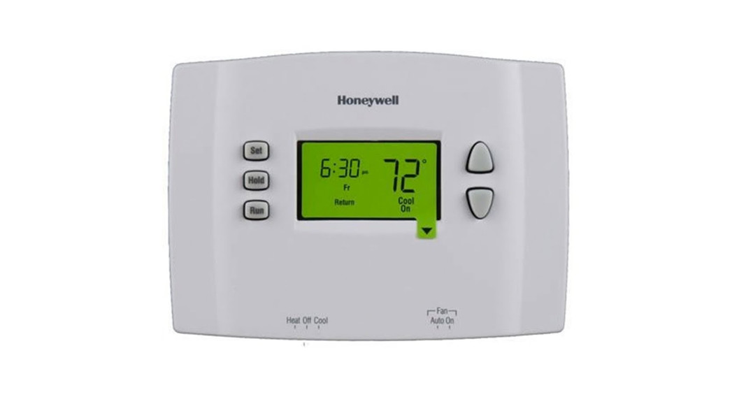
RTH25107-day Programmable Thermostat

 Do you need assistance?We are here to help.Call 1-800-468-1502.
Identify System Type
This thermostat is compatible with the following systems:
- Gas, oil or electric furnace
- Central air conditioner
- Hot water system with or without pump
- Millivolt system
- Central heating and cooling system
- Heat pump without auxiliary/backup heat
- Heat pump with auxiliary/backup heat
This thermostat cannot be used on multistage systems.
Remove Old Thermostat
- Turn the power off at the heating/cooling system.

- Remove old thermostat, but leave wallplate with wires attached.


 MERCURY NOTICE: Do not put your old thermostat in the trash if it contains mercury in a sealed tube. Contact your local waste management authority for instructions regarding recycling and proper disposal.
Identify Wires
If any wires are not attached to your old thermostat or are attached to a terminal marked C or C1, they will not be connected to your new thermostat. Wrap the bare metal end of each of these wires with electrical tape, so it cannot touch and short other wires.

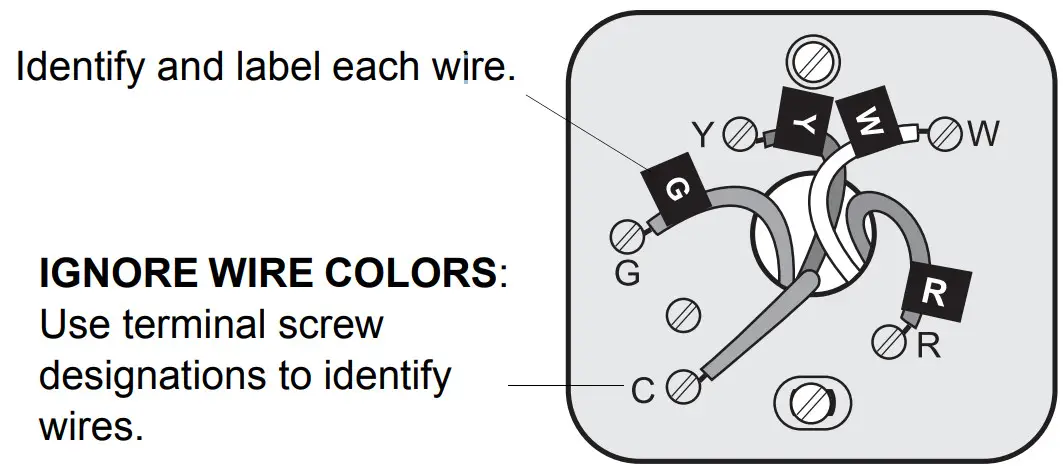
Disconnect wires and remove the old wallplate only after all wires are labeled. Wrap the wires around a pencil to prevent them from falling through the wall opening.
Mount New Wallplate
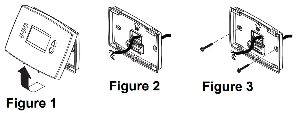
- Loosen the locking screw at the bottom of the thermostat. Note that the screw is captive and cannot be removed from the wallplate.
- Separate the thermostat from the wallplate as per Figure 1.
- Position the wallplate against the wall and mark hole positions with a pencil.NOTE: Levelling is for esthetics only and will not affect the performance of the thermostat.
- Drill holes at the marked positions and insert supplied wall anchors.
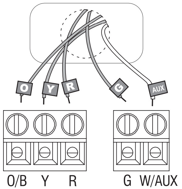
- Pass the wires through the large opening located at the bottom center of the wallplate as per Figure 2.
- Secure the wall plate to the wall with supplied mounting screws as per Figure 3.
- Connect the wires to the terminals.
Connect Wires
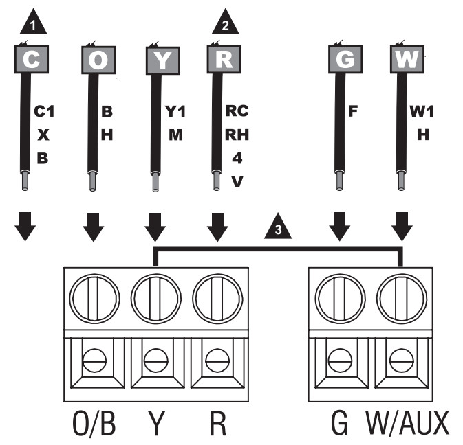
Conventional Systems (Typical Wiring)

- Match each labeled wire with the terminal having the same letter.
- Loosen the terminal screws using a screwdriver, insert the wires, then tighten the screws.
- Push any excess wire back into the wall opening.
- Labels don’t match? See page 6.
- Have a heat pump with auxiliary/backup heat, see pages 7-8.
- Call 1-800-468-1502 for wiring assistance.
Connect Wires (cont’d)
Conventional Systems (Alternate Wiring)
- Do not use C, C1, or X wire. Do not use B wire if you already have O wire. Wrap the bare end of the wire with electrical tape.
- This thermostat cannot be used if your old thermostat had any two of the following wires: R, RC, RH, 4, and V.
- Place a jumper (a piece of wire) between Y and W/AUX if you are using a heat pump without auxiliary/backup heat.
Connect Wires (cont’d)
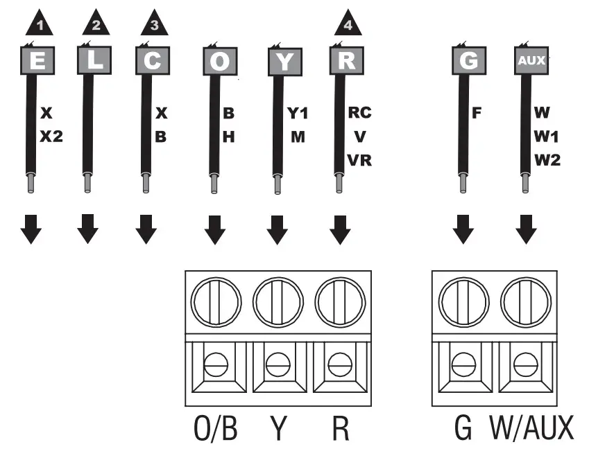
Heat Pump Systems with Auxiliary/Backup Heat (Typical Wiring)
- Match each labeled wire with the terminal having the same letter.
- Loosen the terminal screws using a screwdriver, insert the wires, then tighten the screws.
- Push any excess wire back into the wall opening.
Labels don’t match? See page 8.
Connect Wires (cont’d)
Heat Pump Systems with Auxiliary/Backup Heat (Alternate Wiring)
- If your old thermostat had E and Aux wires (or alternate wires), connect both wires to the AUX terminal.
- Do not use L wire. Wrap the bare end of the wire with electrical tape.
- Do not use C or X wire. Do not use B wire if you already have O wire. Wrap the bare end of the wire with electrical tape.
- This thermostat cannot be used if your old thermostat had any two of the following wires: R, RC, V, or VR.
Set Heating Fan Control
Set jumper JP1, on the back of the thermostat, if you have connected a wire to the G terminal.
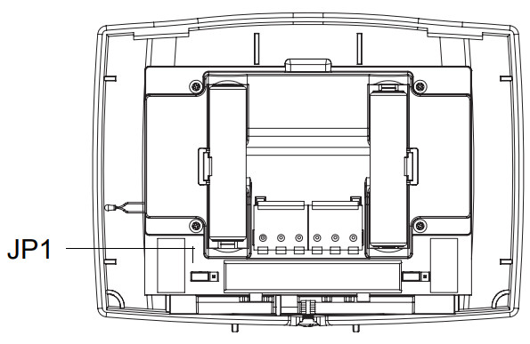
HG Leave the jumper in this factory-set position if you have a gas or oil furnace.HE Place the jumper to this position if you have an electric furnace.Incorrect jumper setting: An incorrect setting is noticeable in a gas or oil heating system. When heating starts, you will initially feel cold air coming out of the vents as the fan is running before the furnace has enough time to heat up the air.
Set Heat Pump Reversing Valve
Set jumper JP2, on the back of the thermostat, if you have a heat pump.
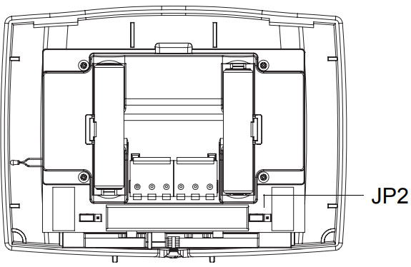
O Leave the jumper in this factory-set position if you have connected O wire to the O/B terminal.B Place the jumper to this position if you have connected B wire to the O/B terminal.Incorrect jumper setting: The heat pump operation will be reversed, i.e., it will cool in Heat mode and will heat in Cool mode.
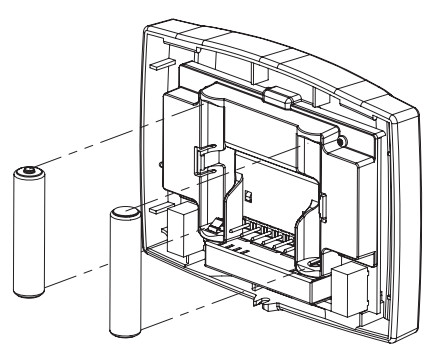
Install Batteries and Thermostat
- Install 2 AAA batteries on the back of the thermostat.
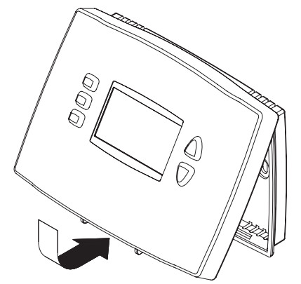
- Align the two brackets on the top of the thermostat with the corresponding slots on the top of the wallplate.
- Push the thermostat against the wallplate.
- Tighten the screw at the bottom of the thermostat.
- Turn the power back on at the heating/ cooling system.

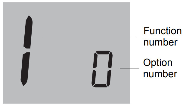
System Setup
Follow the procedure below to personalize and configure the thermostat according to the heating/ cooling system.
- Press the Up and Down buttons simultaneously (for three seconds) until the display appears as shown below. See table on the next page.
- Press the Up or Down button to change the option.
- Press the Up and Down buttons simultaneously for one second to advance to the next function.
- When the last function is displayed, press the Up and Down buttons to save any changes and exit the menu.
NOTE: If you do not press any button for 60 seconds while you are in the setup menu, the thermostat automatically saves any changes made and exits the menu. At any time you can save the changes and exit by pressing the Run button.
System Setup (cont’d)
| Function | Default setting | Options |
| 1. Temperature display format | 0 | 0: Fahrenheit 1: Celsius |
| 2. Time display format | 0 | 0: 12-hour display1: 24-hour display |
| 3. Heating cycles per hour | 5 | 2 to 6 cycles per hour•2: 30 min (steam, gravity)•3: 20 min (hot water, 90%+high-efficiency furnace)•4: 15 min (gas or oil)•5: 12 min (gas or oil)•6: 10 min (electric) |
| 4. Compressor 1protection | 1 | 0: Off1: On |
| 5. Adaptive IntelligentRecovery 2 | 1 | 0: Off1: On |
| 6. System setup | 0 | 0: Conventional system (1H1C) 1: Heat pump system with auxiliary/backup heat (2H1C) |
¹Damage can occur if the compressor is restarted too soon after shutdown. This feature forces the compressor to wait 5 minutes before restarting. During the wait time, the message Cool On or Heat On flashes on the screen. When the safe wait time has elapsed, the message stops flashing and the compressor turns on.
²Adaptive Intelligent Recovery™ allows the thermostat to “learn” how long your furnace or air conditioner takes to reach the set temperature. Simply program the desired times and desired temperatures into the schedule. The thermostat will determine when to activate heating or cooling so that the desired temperature is attained at the desired time.
Automation and Control SystemsHoneywell International Inc.1985 Douglas Drive NorthGolden Valley, MN 55422Honeywell Limited35 Dynamic DriveScarborough, Ontario M1V 4Z9http://DIYthermostats.honeywell.com
Printed in USA69-2380ES-01 10-09
![]()
References
[xyz-ips snippet=”download-snippet”]